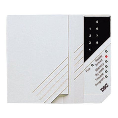
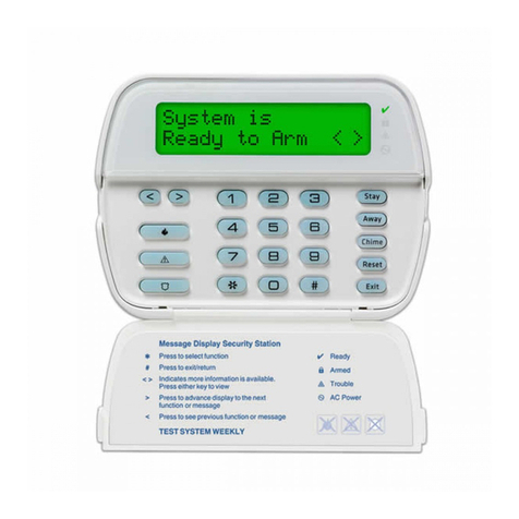
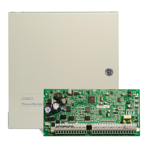
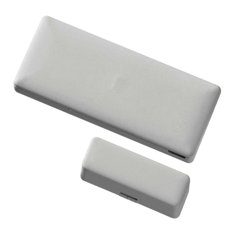
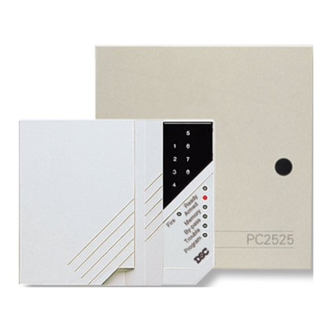
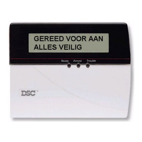
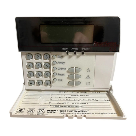
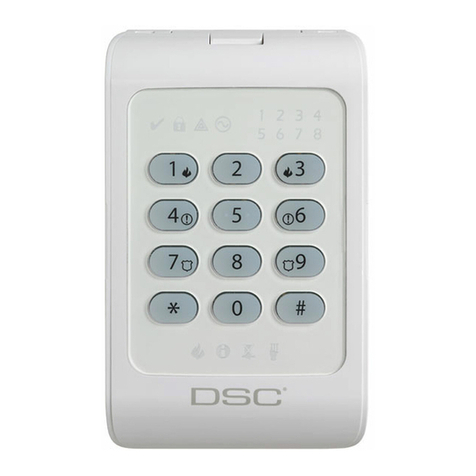
DSC PC1575 Operating instructions

Property of Monitronics Inc
DSC PC1575 Program Sheet
Supported PC5580 Escort
DSC Modules PC5400 Printer Module
DLM-1/DLM-4 Downlook Module
Cannot use PC5132 Wireless Receiver or Sensors
Enter Program *8 1575 (READY, ARMED and TROUBLE Lights should flash)
Exit Program #
Move to location Enter 2-digit location, some areas may require # to exit
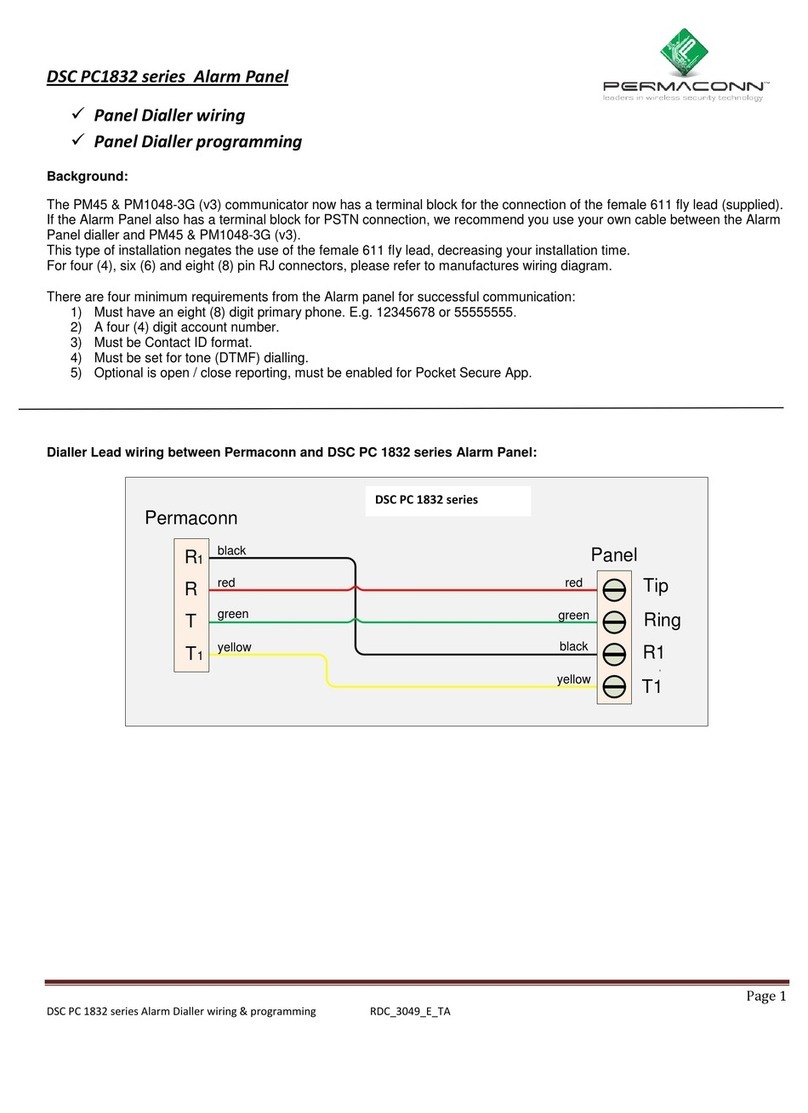
Default Panel 1. Connect wire from Zone 1 to PGM1
2. Power up panel, wait 10 seconds
3. If Zone 1 turns ON panel is defaulted, if not panel is locked
Enable Download *+ 6 + Master Code + 5 (Enables for 1 hour)
(System also enables downloading for 1 hour if powered down then up)
Hex Program A = *1 *, B = *2 *, C = *3 *, D = *4 *, E = *5 *, F = *6 *
[00] Keypad Assignment (must be done at each keypad)
[0] Slot (Valid entries are 11-18 for the Slot)
[1] Function Key 1 Assignment (Default = 03)
[2] Function Key 2 Assignment (Default = 04)
[3] Function Key 3 Assignment (Default = 06)
[4] Function Key 4 Assignment (Default = 14)
[5] Function Key 5 Assignment (Default = 16)
00 Null Key (Not Used) 07 *6 4 System Test 13 *7 1 Utility Output
01 Not used 08 *1 Bypass Mode 14 *7 2 Sensor Reset
02 Not used 09 *2 Trouble Display 15 Not Used
03 Stay Arm 10 *3 Alarm Memory 16 *0 Quick Exit
04 Away Arm 11 *5 User Programming 17 *1 Reactivate Stay/Away's
05 *9 No-Entry Arm 12 *6 User Functions 18 Not Used
06 *4 Chime On/Off
If multiple LCD keypads make 1 slot 8 to enable Zone description programming by downloader
[01] Zone 1-6 Definitions 00 Null (Not Used) 11 24 Hour Burglary
Default 01 Delay 1 12 24 Hour Heat
01 l_____l_____l Zone 1 02 Delay 2 13 Not Used
06 l_____l_____l Zone 2 03 Instant 14 24 Hour Hold-Up
03 l_____l_____l Zone 3 04 Interior 15 24 Hour Auxiliary
03 l_____l_____l Zone 4 05 Interior, Stay/Away 16 24 Hour Panic
03 l_____l_____l Zone 5 06 Delay, Stay/Away 17 24 Hour Emergency
03 l_____l_____l Zone 6 07 Delay 24 Hour Fire 18 24 Hour Sprinkler
08 Standard 24 Hour Fire 19 24 Hour Water
09 24 Hour Supervisory (Links) 20 24 Hour Freeze
10 24 Hour Supervisory Buzzer 21 24 Hour Latching Tamper
[02] System Times
Default
030 I _ _I _ _I _ _I Entry Delay 1 (000 to 255 seconds)
045 I _ _I _ _I _ _I Entry Delay 2 (000 to 255 seconds)
120 I _ _I _ _I _ _I Exit Delay (000 to 255 seconds)
004 I _ _I _ _I _ _I Bell Cut-off (000 to 255 minutes)
[03] Installer's Code
Default
1575 I _1 _I _5 _I _7 _I _5 _I
[04] Master Code
Default
1234 I _ _I _ _I _ _I _ _I
[05] Second Master Code
Default
AAAA I _ _I _ _I _ _I _ _I
Created by Mark Leuck 02/02/2002 Monitronics International, Inc.

Property of Monitronics Inc
DSC PC1575 Program Sheet
[06] PGM Output Programming (PGM 1 and 2)
Default
19 I _ _I _ _IPGM 1
10 I _ _I _ _IPGM 2
Programmable Output Options
01 Ground Start Pulse 12 Police Code Follower
02 User Output with Any Code 13 20 Minute Latched Alarm
[*] [7] [1] + Access Code 14 Line Seizure
03 Sensor Reset [*] [7] [2] 15 Ready to Arm Status
04 Courtesy Pulse 16 Links Support (PGM 1 only)
05 Keypad Buzzer Follow Mode 17 Downlook Support
06 System Armed Status 25 2-Wire Smoke (PGM 2 only)**
07 Strobe Output 26 Momentary Keyswitch Arm (PGM2)
08 Fail to Communicate (TLM Output) 27 Maintained Keyswitch Arm (PGM2)
09 Entry Delay Follower 28 Silent 24 Hour (PGM2)
10 Exit Delay Follower 29 Audible 24 Hour (PGM2)
11 TLM and Alarm 30 Forced Answer (PGM2)
**For 2-Wire Smoke Support Jumper CON1 on board must be removed
[07] Keypad Lockout Options
Default
00 I _ _I _ _INumber of Invalid Codes Before Lockout (001-255 codes)
00 I _ _I _ _ILockout Duration (001-255 minutes)
[08] First System Option Code (Toggle Options ON/OFF, Press # to Exit)
Default Option ON OFF
OFF I _ _I 1 Normally Closed Loops End-of-Line Resistors
OFF I _ON _I 2 Double End-of-Line Resistors Single End-of-Line Resistors
ON I _ON _I 3 Fire Key Enabled Disabled
OFF I _ON _I 4 Police Key Audible Silent
ON I _ON _I 5 TLM Enabled Disabled
OFF I _ON _I 6 TLM Audible when Armed TLM Trouble Only
[09] Second System Option Code (Toggle Options ON/OFF, Press # to Exit)
Default Option ON OFF
OFF I OFF_I 1 Master Code Not Changable Master Code Changable
OFF I OFF_I 2 Code Required to Bypass No Code Required
OFF I _ON _I 3 6th Code is Duress Code 6th Code is Normal Code
OFF I OFF_I 4 Quick Exit Enabled Quick Exit Disabled
OFF I OFF_I 5 Bypass Status Displayed w/Armed Bypass Not Displayed w/Armed
ON I _ON _I 6 AC Trouble Displayed AC Trouble Not Displayed
[10] Third System Option Code (Toggle Options ON/OFF, Press # to Exit)
Default Option ON OFF
OFF I OFF_I 1 Arm/Disarm Bell Squawk Enabled Disabled
OFF I OFF_I 2 Bell Squawk During Auto Arm Disabled
OFF I OFF_I 3 Bell Squawk On Exit Delay Disabled
OFF I OFF_I 4 Bell Squawk On Entry Delay Disabled
ON I _ON _I 5 Audible Exit With Urgency Silent Exit Delay
ON I _ON _I 6 Quick Arm Enabled Quick Arm Disabled
[11] Fourth System Option Code (Toggle Options ON/OFF, Press # to Exit)
Default Option ON OFF
OFF I OFF_I 1 For Future Use
ON I _ON _I 2 Event Buffer Follow Swinger Event Buffer always ON
ON I _ON _I 3 Trouble Light Flashes if AC Fails Light does not Flash
OFF I OFF_I 4 Exit Delay Termination Enabled Disabled
OFF I OFF_I 5 Keypad Blanking Enabled Disabled
OFF I OFF_I 6 Keypad Tampers Enabled Disabled
Zone Attributes (Normally leave alone)
ON Audible Steady Chime Force Bypass Downlook
OFF Silent Pulsed No No No No
[21] Zone 1 I _ _II _ _II _ _II _ _II _ _I I _ _I
[22] Zone 2 I _ _II _ _II _ _II _ _II _ _I I _ _I
[23] Zone 3 I _ _II _ _II _ _II _ _II _ _I I _ _I
[24] Zone 4 I _ _II _ _II _ _II _ _II _ _I I _ _I
[25] Zone 5 I _ _II _ _II _ _II _ _II _ _I I _ _I
[26] Zone 6 I _ _II _ _II _ _II _ _II _ _I I _ _I
Created by Mark Leuck 02/02/2002 Monitronics International, Inc.
Property of Monitronics Inc
DSC PC1575 Program Sheet
[31] First Telephone Number (32 Digits)
I _ _I _ _I _ _I _ _I _ _I _ _I _ _I _ _I _ _I _ _I _ _I _ _I _ _I _ _I _ _I _ _I _ _I _ _I
*2 = *, *3 = #, *4 = Wait for Dial Tone, *5=2 Sec Pause, *6 End Number
(If adding more than one hex digit Example: *555*gives 3 2-second pauses)
[32] Second Telephone Number (32 Digits)
I _ _I _ _I _ _I _ _I _ _I _ _I _ _I _ _I _ _I _ _I _ _I _ _I _ _I _ _I _ _I _ _I _ _I _ _I
If Pager program Number + pauses *5555*gives 4 2-second pauses
Pager will not send properly if Hex Characters A C D F are in Account Number
[33] Third Telephone Number (32 Digits)
I _ _I _ _I _ _I _ _I _ _I _ _I _ _I _ _I _ _I _ _I _ _I _ _I _ _I _ _I _ _I _ _I _ _I _ _I
[34] First/Third Telephone Number Account Code
I _ _I _ _I _ _I _ _I
[35] Second Telephone Number Account Code
I _ _I _ _I _ _I _ _I
[36] Alarm Reporting Codes, Zones 1-6
Default Default
FF I _F _I _F _I Zone 1 Alarm FF I _F _I _F _I Zone 4 Alarm
FF I _F _I _F _I Zone 2 Alarm FF I _F _I _F _I Zone 5 Alarm
FF I _F _I _F _I Zone 3 Alarm FF I _F _I _F _I Zone 6 Alarm
[37] Alarm Restoral Reporting Codes Zones 1-6
Default Default
FF I _F _I _F _I Zone 1 Alarm Restoral FF I _F _I _F _I Zone 4 Alarm Restoral
FF I _F _I _F _I Zone 2 Alarm Restoral FF I _F _I _F _I Zone 5 Alarm Restoral
FF I _F _I _F _I Zone 3 Alarm Restoral FF I _F _I _F _I Zone 6 Alarm Restoral
[38] Tamper Reporting Codes Zones 1-6
Default Default
FF I _F _I _F _I Zone 1 Alarm Tamper FF I _F _I _F _I Zone 4 Alarm Tamper
FF I _F _I _F _I Zone 2 Alarm Tamper FF I _F _I _F _I Zone 5 Alarm Tamper
FF I _F _I _F _I Zone 3 Alarm Tamper FF I _F _I _F _I Zone 6 Alarm Tamper
[39] Tamper Restoral Reporting Codes Zones 1-6
Default Default
FF I _F _I _F _I Zone 1 Alarm Tamper Restoral FF I _F _I _F _I Zone 4 Alarm Tamper Restoral
FF I _F _I _F _I Zone 2 Alarm Tamper Restoral FF I _F _I _F _I Zone 5 Alarm Tamper Restoral
FF I _F _I _F _I Zone 3 Alarm Tamper Restoral FF I _F _I _F _I Zone 6 Alarm Tamper Restoral
[40] Priority Alarm and Restoral
Default Default
FF I _F _I _F _I Keypad Fire Panic Alarm FF I _F _I _F _I Keypad Fire Panic Restoral
FF I _F _I _F _I Keypad Medical Panic Alarm FF I _F _I _F _I Keypad Medical Panic Restoral
FF I _F _I _F _I Keypad Police Panic Alarm FF I _F _I _F _I Keypad Police Panic Restoral
FF I _F _I _F _I PGM2 Alarm FF I _F _I _F _I PGM2 Restoral
FF I _F _I _F _I Duress Code
[41] Closing (Arming) Reporting Codes Access Codes 1-6
Default Default
FF I _F _I _F _I User 1 Closing FF I _F _I _F _I User 4 Closing
FF I _F _I _F _I User 2 Closing FF I _F _I _F _I User 5 Closing
FF I _F _I _F _I User 3 Closing FF I _F _I _F _I User 6 Closing
[42] Opening (Disarming) Reporting Codes Access Codes 1-6
Default Default
FF I _F _I _F _I User 1 Opening FF I _F _I _F _I User 4 Opening
FF I _F _I _F _I User 2 Opening FF I _F _I _F _I User 5 Opening
FF I _F _I _F _I User 3 Opening FF I _F _I _F _I User 6 Opening
[43] Maintenance Alarm Reporting Codes
Default Default
FF I _F _I _F _I Battery Trouble FF I _F _I _F _I Aux Fuse Failure Alarm
FF I _F _I _F _I AC Failure Trouble FF I _F _I _F _I TLM Trouble (via LINKS)
FF I _F _I _F _I Bell Circuit Trouble FF I _F _I _F _I General System Supervisory
FF I _F _I _F _I Fire Trouble Alarm
Created by Mark Leuck 02/02/2002 Monitronics International, Inc.
Property of Monitronics Inc
DSC PC1575 Program Sheet
[44] Maintenance Restoral Reporting Codes
Default Default
FF I _0 _I _0 _I Battery Trouble Restore FF I _0 _I _0 _I Aux Fuse Failure Restore
FF I _1 _I _1 _I AC Failure Trouble Restore FF I _0 _I _0 _I TLM Trouble Restore
FF I _0 _I _0 _I Bell Circuit Trouble Restore FF I _0 _I _0 _I General System Supervisory
FF I _1 _I _1 _I Fire Trouble Restore Restore
[45] Miscellaneous Maintenance Reporting Codes
Default
FF I _1 _I _1 _I Phone Number 1 FTC
FF I _0 _I _0 _I Phone Number 1 FTC Restoral
FF I _0 _I _0 _I Event Buffer 75% Full
FF I _0 _I _0 _I General Zone Fault Alarm
FF I _0 _I _0 _I General Zone Fault Restoral
FF I _0 _I _0 _I Delinquency Report Code
[46] Test Transmission Reporting Codes
Default
FF I _F _I _F _I Periodic Test Transmission
FF I _F _I _F _I System Test Report
FF I _F _I _F _I Links 1000 Test Transmission Report
[50] Communicator Format Options (If SIA reporting leave all Report Codes alone)
Default
02 I _0 _I 4_I 1st Phone Number 01 20 BPS 1400 HZ 03 DTMF CONTACT ID
02 I _0 _I 4_I 2nd Phone Number 02 20 BPS 2300 HZ 04 SIA FSK
05 Pager
[51] Alarm/Restore Communicator Call Directions
Default Option ON OFF
ON I _ON _I 1 1st Telephone Number Disabled
OFF I OFF_I 2 2nd Telephone Number Disabled
OFF I OFF_I 3 1st Telephone Number (LINKS) Disabled
OFF I OFF_I 4 2nd Telephone Number (LINKS) Disabled
OFF I OFF_I 5-8 For Future Use
[52] Tamper/Restore Communicator Call Directions
Default Option ON OFF
ON I _ON _I 1 1st Telephone Number Disabled
OFF I OFF_I 2 2nd Telephone Number Disabled
OFF I OFF_I 3 1st Telephone Number (LINKS) Disabled
OFF I OFF_I 4 2nd Telephone Number (LINKS) Disabled
OFF I OFF_I 5-8 For Future Use
[53] Opening/Closing Communicator Call Directions
Default Option ON OFF
ON I OFF_I 1 1st Telephone Number Disabled
OFF I OFF_I 2 2nd Telephone Number Disabled
OFF I OFF_I 3 1st Telephone Number (LINKS) Disabled
OFF I OFF_I 4 2nd Telephone Number (LINKS) Disabled
OFF I OFF_I 5-8 For Future Use
[54] System Maintenance Alarm/Restore Communicator Call Directions
Default Option ON OFF
ON I _ON _I 1 1st Telephone Number Disabled
OFF I OFF_I 2 2nd Telephone Number Disabled
OFF I OFF_I 3 1st Telephone Number (LINKS) Disabled
OFF I OFF_I 4 2nd Telephone Number (LINKS) Disabled
OFF I OFF_I 5-8 For Future Use
[55] System Test Transmissions Communicator Call Directions
Default Option ON OFF
ON I _ON _I 1 1st Telephone Number Disabled
OFF I OFF_I 2 2nd Telephone Number Disabled
OFF I OFF_I 3 1st Telephone Number (LINKS) Disabled
OFF I OFF_I 4 2nd Telephone Number (LINKS) Disabled
OFF I OFF_I 5-8 For Future Use
Created by Mark Leuck 02/02/2002 Monitronics International, Inc.
Property of Monitronics Inc
DSC PC1575 Program Sheet
[60] First Communicator Option Code
Default Option ON OFF
ON I _ON _I 1 Communications Enabled Communications Disabled
OFF I _ON _I 2 DTMF Dialing Pulse Dialing
OFF I _ON _I 3 Switch to Pulse on 5th Attempt DTMF Dial For All Attempts
ON I OFF_I 4 3rd Phone Number enabled 3rd Phone Number disabled
OFF I OFF_I 5 Alternate Dial (1st and 3rd) Call 1st Number, Backup to 3rd
OFF I OFF_I 6 Restorals on Bell Time-Out Restorals Follow Zones
[61] Second Communicator Option Code
Default Option ON OFF
ON I _ON _I 1 Closing Confirmation Enabled Disabled
OFF I OFF_I 2 Open After Alarm KP Ringback Disabled
OFF I OFF_I 3 Open After Alarm Bell Ringback Disabled
ON I OFF_I 4 Busy Tone Detection Enabled Disabled
OFF I OFF_I 5 Call Links as well as Land Line Links is Backup
OFF I OFF_I 3 SIA sends Programmed Reports SIA sends Automatic Codes
[62] Communication Variables
Default
003 I _ _I _ _I _ _ISwinger Shutdown (Alarm & Rest) (001-014, 000=Disable)
000 I _ _I _ _I _ _ITransmission Delay (001-255 seconds, 000 = No Delay)
030 I _ _I _ _I _ _IAC Failure Communication Delay (001-255 minutes)
003 I _ _I _ _I _ _ITLM Trouble Delay (No. of checks req. - valid entries 003 - 255)
030 I _ _I _ _I _ _ITest Transmission Cycle (Land line) (001-255 days)
030 I _ _I _ _I _ _ITest Transmission Cycle (LINKS) (001-255 days)
030 I _ _I _ _I _ _IDelinquency Transmission Cycle (001-255 days / hours)
[63] Test Transmission Time of Day
Default
9999 I _0 _I _2 _I _0 _I _0 _I
[67] LINKS Preamble (First Telephone Number)
Default
FFFF I _F _I _F _I _F _I _F _I
[68] LINKS Preamble (Second Telephone Number)
Default
FFFF I _F _I _F _I _F _I _F _I
[69] LINKS Preamble (Third Telephone Number)
Default
FFFF I _F _I _F _I _F _I _F _I
[70] Number of Rings to Answer Download Request
Default
000 I _0 _I _1 _I _0 _I
[71] First Downloading Option Code (Toggle Options ON/OFF, Press # to Exit)
Default OPTION ON OFF
OFF I _ON _I 1 Downloading Answer Enable Disabled
ON I _ON _I 2 User Can Enable Download Disabled
OFF I OFF_I 3 Callback Enabled Disabled
OFF I OFF_I 4 User Initiated Call-Up Enabled Disabled
OFF I OFF_I 5 Periodic Downloading Disabled
OFF I _ON _I 6 Answer Machine Override Disabled
[72] Downloading Computer's Telephone Number (32 Digits)
I _ L _I _ E _I _ A _I _ V _I _ E _I _ _I _ B _I _ L _I _ A _I _ N _I _ K _I _ _I _ _I _ _I _ _I _ _I _ _I
[73] Downloading Access Code
Default
1575 I _1 _I _5 _I _7 _I _5 _I
[74] Panel Identification Code
Default
1575 I _1 _I _5 _I _7 _I _5 _I
[75] Answering Machine Double-call Timer
Default
060 I _0 _I _4 _I _0 _I
[77] [Installer's Code] [77] Initiate PC-Link (Local Downloading)
[79] LINKS Preamble (Downloading Telephone Number)
FFFF I _F _I _F _I _F _I _F _I
Created by Mark Leuck 02/02/2002 Monitronics International, Inc.
Property of Monitronics Inc
DSC PC1575 Program Sheet
Module Programming
[87] PC5400 Printer Module Programming
[01] Printer Configuration
Default Option ON OFF
OFF I OFF_I 1 Printer Enabled Printer Disabled
ON I OFF_I 2 Handshake from Printer No Handshake
OFF I OFF_I 3 80 Column Printer 40 Column Printer
OFF I OFF_I 4 300 Baud Enabled Disabled
OFF I OFF_I 5 1200 Baud Enabled Disabled
OFF I _ON _I 6 2400 Baud Enabled Disabled
[05] Printer Language Selection
Default
01 I _0 _I _1 _I 01 = English
02 = French
03 = Spanish
[88] Downlook DLM-1/DLM-4 Support Timers
Default
01 I _0 _I _1 _I Number of Pictures (01 to 08)
00 I _0 _I _0 _I Delay before Capture in 100ms Increments (00 to 99)
Special Installer Functions
[90] Installer Lockout Enable 90 + Installer Code + 90
[91] Installer Lockout Disable 91 + Installer Code + 91
[92] Module Supervision Reset 92 + Installer Code + 92
[95] Restore PC5580 ESCORT to Factory Default 95 + Installer Code + 95
[97] Restore PC5400 to Factory Default 97 + Installer Code + 97
[99] Restore PC1575 to Factory Default 99 + Installer Code + 99
Created by Mark Leuck 02/02/2002 Monitronics International, Inc.
Property of Monitronics Inc
Monitronics Monitoring and Service: 1-800-447-9239
DSC PC1575 Quick Reference Guide
Arm Away Hold AWAY key for 2 seconds (if available)
or enter User Code
Arm Stay Hold STAY key for 2 seconds (if available)
or enter User Code and do not leave
Instant Doors Press ¬9 then enter User Code
Disarming /
Silencing Alarm Enter 4 digit code
Press # key if a mistake is made entering User Code or to eliminate flashing keypad if an alarm has occurred
Zone Bypassing Press ¬1 then enter Zone to bypass (1 to 6) (Zone bypassed will light on keypad)
When finished press #
Note:
Some systems may require pressing ¬1 + Master Code then the zone to bypass (1 to 6)
User Codes
Press ¬5 then enter Master Code
Enter User (1 to 6)
Enter new 4-digit User Code then # to exit
To erase a code repeat steps above except enter¬instead of a new User Code
The 1st code is the system Master, the 6th code is a Hostage (if programmed)
Door Chimes Hold CHIME button for 2 seconds (if available)
or press ¬4
Reset Smoke Detector Press ¬then 72
Trouble Light If SYSTEM or TROUBLE Light turns ON press ¬then 3
Light 1: Battery trouble Light 2: AC loss Light 3: Communications Trouble
Light 4: Zone fault Light 5: Zone Tamper Light 6: Loss of Time
Alarm Memory Press ¬then 3, the zone or zones that caused last alarm will flash.
Created by Mark Leuck 02/02/2002 Monitronics International, Inc.
Other manuals for PC1575
1
Table of contents
Other DSC Security System manuals

DSC
DSC PowerSeries RFK5500 User manual

DSC
DSC PowerSeries Neo TL280LE User manual

DSC
DSC PC15OO User manual

DSC
DSC PC5102-433 User manual

DSC
DSC PC1550 User manual

DSC
DSC WS4965 User manual

DSC
DSC PC5015 User manual

DSC
DSC 2550 Instruction Manual

DSC
DSC PC15OO User manual

DSC
DSC PowerSeries PTK5507 User manual

DSC
DSC Neo Power HS2016 User manual

DSC
DSC PC1575 User manual

DSC
DSC PC560 User manual

DSC
DSC PowerSeries Neo HS2064 E User manual

DSC
DSC PK5500/RFK5500 User manual

DSC
DSC Power832 User manual

DSC
DSC Power832PC5010 CP-01 User manual

DSC
DSC PC1500 User manual

DSC
DSC PC51O User manual

DSC
DSC Power 832 User manual