3 … 16
M/CD • Edition 04.12 • Nr. 219 502
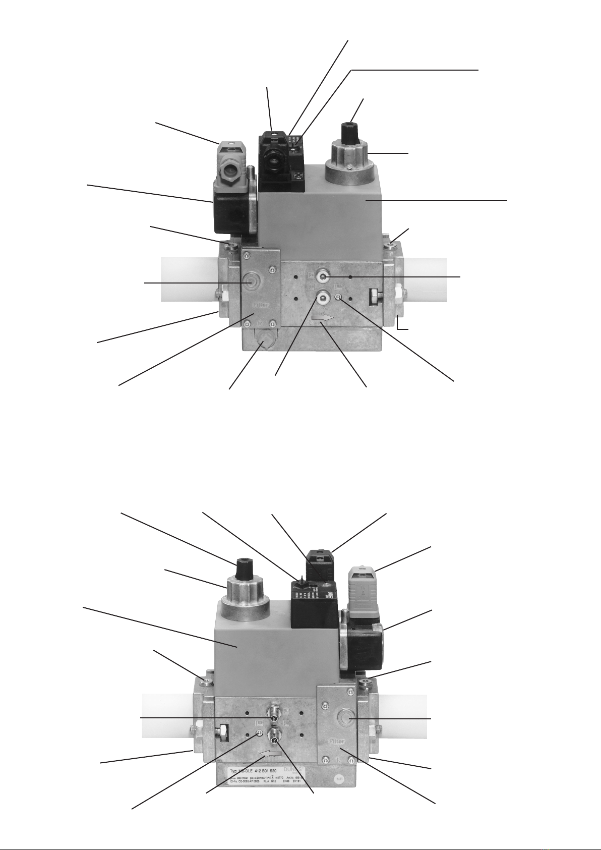
Meßanschluß G 1/8 vor V1
beidseitig möglich
Test point connection G 1/8
upstream of V1, possible on
both sides
Prise de pression G 1/8 avant
V1 possible des deux côtés
Attacco misuratore G 1/8 pos-
sibile sui due lati
Atmungsdüse, Regler
Vent nozzle, regulator
Mise à l'atmosphère, régulateur
Ugellodisato,regolatore
Übersicht/Overview/Tableau/Sommario
Druckwächter
Pressure switch
Pressostat
Pressostato
Meßanschluß G 1/8 vor dem Filter,
beidseitig möglich
Test point connection G 1/8 upstream
oflter,possibleonbothsides
PrisedepressionG1/8avantleltre
possible des deux côtés
Attacco misuratore G 1/8 prima del ltro
possibile sui due lati
Meßanschluß M4 nach Ventil 2
Test point connection M4 downstream of valve 2
Prise de pression M4 après V2
Attacco misuratore M4 dopo valvola 2
Ausgangsansch
Outputange
Bride de sortie
Flangia in uscita
Meßanschluß G 1/8 nach Ventil 1,
beidseitig möglich
Test point connection G 1/8 downstream
of valve 1, possible on both sides
Prise de pression G 1/8 après V1 possible
des deux côtés
Possibilità attacco misuratore G 1/8 dopo
valvola 1 su entrambi i lati
Meßanschluß G 1/8 möglich
Test point connection G 1/8 possible
Prise de pression G 1/8 possible
Possibilità attacco misuratore G 1/8
Magnet
Solenoid
Bobine
Bobina
Hydraulikbremse oder Einstellteller
Hydraulic brake or setting plate
Frein hydraulique ou bouton de réglage
Freno idraulico o piatello di regolazione
Einstellkappe
Setting cap
Bouton de réglage
Coperchietto di regolazione
Betriebsanzeige V1, V2 (optional)
Operation display V1, V2 (optional)
Indicateur de marche V1, V2 (option)
Indicatore di esercizio V1, V2 (optional)
Elektrischer Anschluß Ventile
(Stecker DIN EN 175 301-803)
Electrical connection for valves
(DIN EN 175 301-803 connector)
Raccordement électrique de l'électro-
vanne (connecteurs DIN EN 175 301-803)
Allacciamento elettrico valvole
(spina DIN EN 175 301-803)
Elektrischer Anschluß Druckwächter
(Stecker DIN EN 175 301-803)
Electrical connection for pressure switch
(DIN EN 175 301-803 connector)
Raccordement électrique du pressostat
(connecteurs DIN EN 175 301-803)
Allacciamento elettrico pressostato
(spin DIN EN 175 301-803)
Meßanschluß G1/8 möglich
Test point connection G 1/8 possible
Prise de pression G 1/8 possible
Possibilità attacco misuratore G 1/8
Plombierungsöse
Lead seal eye
Oeillet de plombage
Occhiello per piombatura
Gasußrichtung
Gasowdirection
Directionduuxdegaz
Direzioneussogas
Meßanschluß G 1/8 möglich
Test point connection G 1/8 possible
Prise de pression G 1/8 possible
Possibilità attacco misuratore G 1/8
Meßanschluß G 1/8 nach Ventil 1,
beidseitig möglich
Test point connection G 1/8 downstream
of valve 1, possible on both sides
Prise de pression G 1/8 après
V1 possible des deux côtés
Possibilità attacco misuratore
G 1/8 dopo valvola 1 su
entrambi i lati
Ausgangsansch
Outputange
Bride de sortie
Flangia in uscita
Magnet
Solenoid
Bobine
Bobina
Hydraulikbremse oder Einstellteller
Hydraulic brake or setting plate
Frein hydraulique ou bouton de réglage
Freno idraulico o piatello di regolazione
Einstellkappe
Setting cap
Bouton de réglage
Coperchietto di regolazione
Plombierungsöse
Lead seal eye
Oeillet de plombage
Occhiello per piombatura
Elektrischer Anschluß Ventile (Stecker DIN EN 175 301-803)
Electrical connection for valves (DIN EN 175 301-803 connector)
Raccordement électrique de l'électro-vanne (connecteurs DIN EN 175 301-803)
Allacciamento elettrico valvole (spina DIN EN 175 301-803)
Betriebsanzeige V1, V2 (optional)
Operation display V1, V2 (optional)
Indicateur de marche V1, V2 (option)
Indicatore di esercizio V1, V2 (optional)
Elektrischer Anschluß Druckwächter
(Stecker DIN EN 175 301-803)
Electrical connection for pressure switch
(DIN EN 175 301-803 connector)
Raccordement électrique du pressostat
(connecteurs DIN EN 175 301-803)
Allacciamento elettrico pressostato
(spina DIN EN 175 301-803)
Druckwächter
Pressure switch
Pressostat
Pressostato
Meßanschluß G1/8 möglich
Test point connection G 1/8 possible
Prise de pression G 1/8 possible
Possibilità attacco misuratore G 1/8
Gasußrichtung
Gasowdirection
Directionduuxdegaz
Direzioneussogas
Meßanschluß G 1/8 vor V1 beidseitig möglich
Test point connection G 1/8 upstream of V1, possible on both sides
Prise de pression G 1/8 avant V1 possible des deux côtés
Attacco misuratore G 1/8 possibile sui due lati
Filter (unter Deckel)
Filter (below cover)
Filtre (sous le couvercle)
Filtro (sotto il coperchio)
Eingangsansch
Inputange
Bride d'entrée
Flangia in entrata
Meßanschluß G 1/8 vor dem Filter,
beidseitig möglich
Test point connection G 1/8 upstream
oflter,possibleonbothsides
PrisedepressionG1/8avantleltre
possible des deux côtés
Attacco misuratore G 1/8 prima del ltro
possibile sui due lati
Meßanschluß M4 nach Ventil 2
Test point connection M4
downstream of valve 2
Prise de pression M4 après V2
Attacco misuratore M4 dopo valvola 2
Filter (unter Deckel)
Filter (below cover)
Filtre (sous le couvercle)
Filtro (sotto il coperchio)
Eingangsansch
Inputange
Bride d'entrée
Flangia in entrata