manuals.online logo
Brands
  1. Home
  2. •
  3. Brands
  4. •
  5. Dunster House
  6. •
  7. Outdoor Furnishing
  8. •
  9. Dunster House H3-GS3X4 User manual

Dunster House H3-GS3X4 User manual

Installation Manual
For
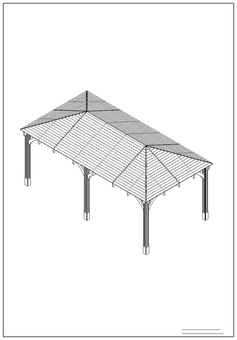
Utopia Gazebo 3x4m
H3-GS3X4
Unique product reference number
.........................................................................
http://www.dunsterhouse.co.uk
Dunster House Ltd.
Queries Procedure
Important Information
Please retain all documentation with regards to your purchase.
In the unlikely event that you need to contact us, please do so in writing to:
Email: cs@dunsterhouse.co.uk
Post: FAO Customer Services, Dunster House Ltd - Factory 1, Caxton Road, Bedford, MK41 0LF
Our Customer Services department is open 9:00 - 17:00, Monday to Friday. Please include your Sales Order number
starting with SO or your postcode so we can locate your order.
The nature of timber
The timber provided for this product is a soft wood which has been kiln dried and is pressure treated for protection
against rot and insect infestation.
Timber is a natural product and inherent properties can include knots, knot holes, imperfections, cracks and warping.
Due to the inherent properties of timber we make no guarantees that the timber you receive for your product will be
free from these natural properties. We will not replace any components for any of the following reasons:
•Timber that contains knots where they do not influence the structural stability of the product
•Cosmetics appearances - colour variations
•Timber that has shakes, cracks, gaps or sap which do not influence the structural strength of the product
•Timber that has been covered or buried underground
•Twisted timber that can be installed
•Queries arising from a neglectful manner during assembly or as a result of incorrect assembly
•Queries due to modifications by the owner causing the timber to deform
Any valid queries will be satisfied by the exchange or replacement of the defective parts only on a supply only basis.
Colour transfer
This product has been pressure treated with wood preservative and a brown colour additive. Consideration should be
given to the propensity of the material to stain light colour adjacent surfaces, such as paving flags, render or coated
timber surfaces. We recommend contact between the timber and these surfaces is limited, and careful consideration to
storing the product prior to assembly should be taken in order to prevent such discolouration.
Assembly Preparation
This product has been designed for self-assembly and recommend that assembly is carried out by two DIY competent
people. It is important that the assembly instructions are followed carefully and we recommend that the assembly
instructions are read through in their entirety prior to assembly to allow you to familiarise yourself first.
We recommend ensuring that the product is assembled in an appropriate location and on an appropriate base for
the product. It is imperative that the product is installed square, level and plumb.
To assemble your product we recommend that you have the following:
•Stepladder
•Drill and 3mm drill bit
•Spirit level
•Tape measure
•Screwdriver
•Rubber mallet
•Gloves - if you wish for extra protection when handling pressure treated timber
All screw holes need to be pre-drilled using a 3mm drill bit (not provided) to avoid timber splitting.
Pressure treated products do not need to be treated immediately or have a timber preservative applied.
Pressure treatment does not mean that the timbers are waterproof, so you may wish to apply a water repellent.
Page 1
70x70x1900.F
4x
Wall Post
70x70x1900.H
2x
Wall Post
86x43x3930.B
2x
Roof Support
86x43x3000.C
2x
Roof Support
86x43x2116.B
4x
Purlin
70x35x2340.A
4x
Roof Cover Board
35x35x2347
2x
Temporary Support Post
70x35x1600.C
1x
Roof Brace
70x35x1594.A
6x
Purlin
70x35x965
1x
Purlin
70x35x1557.B
2x
Purlin
Page 2
Component details for Utopia Garden Shelter
All dimensions are approximate and subject to the limitations of the material used and the methods of manufacture
1900 70
70
70
70
1900
3930 43
81
43
81
3000
43
86
2116
2340 70
30
35
35
2347
35
70
1600
35
70
1557.3
35
70
965
1557.3 35
70
70x35x850.DM
4x
Purlin Support
70x35x650.C
12x
Post Braces
70x35x350.C
10x
Post Trims
70x35x850.D
4x
Purlin Support
70x35x925.A
1x
Roof Covering Board
SHIPx248.C
2x
Roof Board
SHIPx457.B
2x
Roof Board
SHIPx665.C
2x
Roof Board
SHIPx874.B
2x
Roof Board
SHIPx1083.B
2x
Roof Board
SHIPx1291.B
2x
Roof Board
Page 3
Component details for Utopia Garden Shelter
All dimensions are approximate and subject to the limitations of the material used and the methods of manufacture
35
70
850
650 35
70
35350
7070
35850
925
248
121
15
457
121
15
121
15665
121
15874
1083
121
15
1291
121
15
70
30
SHIPx1500.C
2x
Roof Board
SHIPx1708.C
2x
Roof Board
SHIPx1917.C
2x
Roof Board
SHIPx2125.B
2x
Roof Board
SHIPx2334.C
2x
Roof Board
SHIPx2543.B
2x
Roof Board
SHIPx2751.B
2x
Roof Board
SHIPx2960.C
2x
Roof Board
SHIPx3169.B
2x
Roof Board
SHIPx1157.A
2x
Roof Board
SHIPx1366.A
2x
Roof Board
SHIPx1575.A
2x
Roof Board
Page 4
Component details for Utopia Garden Shelter
All dimensions are approximate and subject to the limitations of the material used and the methods of manufacture
1500
121
15
15
121
1708
121
15
1917
121
152125
2334 15
121
121
2543 15
121
152751
121
15
2960
3169
121
15
1157
121
15
1366
121
15
121
151575
SHIPx1784.A
2x
Roof Board
SHIPx1993.A
2x
Roof Board
SHIPx2202.A
2x
Roof Board
SHIPx2410.A
2x
Roof Board
SHIPx2619.A
2x
Roof Board
SHIPx2828.A
2x
Roof Board
SHIPx3037.A
2x
Roof Board
SHIPx3246.A
2x
Roof Board
SHIPx3455.A
2x
Roof Board
SHIPx3663.A
2x
Roof Board
SHIPx3872.A
2x
Roof Board
SHIPx4081.A
2x
Roof Board
Page 5
All dimensions are approximate and subject to the lim itations of the material used and the methods of manufacture
Component details for Utopia Garden Shelter
1784
121
15
1993
121
15
15
121
2202
121
15
2410
121
152619
2828
121
15
121
153037
121
15
3246
3455
121
15
3663
121
15
121
153872
121
154081
Component details for Utopia Garden Shelter
Page 6
All dim ensions are approximate and subject to the limitations of the material used and the methods of manufacture
Please note!
Before you start assembling this garden shelter, you need to prepare a correct foundation.
Only a completely levelled load bearing foundation will ensure a stable and problem free
installation, especially when aligning the optional wall panels.
Read the whole manual including 'post installation' page, before starting installation of the
summerhouse.
ACCESSORIES
Description QTY
70mm screws 104
90mm screws 10
50mm nails 450
M10x 20mm Washer 4
M10 Hex Head Nut 2
M10x 90mm Hex Bolt 2
50mm Screws 8
Installation instruction 1
Utopia 430 Gazebo 3m x 4m Installation Manual
Page 7
All dim ensions are approximate and subject to the limitations of the material used and the methods of manufacture
Step 1
Components required:
Wall posts - 70x70x1900.F (4 required)
Roof Support - 86x43x3000.C (2 required)
Roof Support - 86x43x3930.B (2 required)
70mm Screws (16 required)
Please remember to pre-drill all holes before fixing,
to avoid the splitting of timber.
Start by assembling assembling the main frame for
the Utopia Gazebo
At the notched end of wall posts 70x70x1900.F fix the roof supports
2x 86x43x3930.B, and 86x43x3000.C in the position shown using
2x 70mm screws per end. Ensure that the notch is facing inwards in all
4 corners before fixing.
We recommend to secure the gazebo legs to the ground using metal
brackets, metal connectors etc. (not supplied)
Make sure the notches on the wall
posts 70x70x1900.F are facing
inside the Gazebo. 70mm Screws
70x70x1900.F
86x43x3930.B
70x70x1900.F
86x43x3000.C
70x70x1900.F
86x43x3000.C
Flush with top of
the wall posts
No overlap
Secure using
2x70mm screws
per end.
Wall Posts and Roof Supports layout
Ensure that the diagonals A & B are equal.
Please note that this layout is to assist you with
step 2.
A
B
3930
3000
3086
2860
3790
4016
86x43x3000.C
86x43x3930.B
70x70x1900.F
Installation Manual for Utopia Garden Shelter
Page 8
Position the middle wall posts (70x70x1900.H) in the position shown in the diagram. Ensuring that the components
(70x70x1900.H) is 1860mm from the sides, fix into position using 2x 70mm Screws
Step 1 - Assembling shelter frame
To avoid splitting timber, please pre-drill all holes
All dimensions are approximate and subject to the limitations of the material used and the methods of manufacture
1
8
6
01
8
6
0
2
8
6
0
1
8
6
01
8
6
0
2
8
6
0
70x70x1900.H
70x70x1900.H
Step 2 - Fixing Post Braces
Once the frame is assembled fix the Post Braces
(12x - 70x35x650.C) in the positions shown
using 3x 70mm screws and 1x 90mm screw
per component
70x35x650.C
70x35x650.C
70x35x650.C
70x35x650.C
70x35x650.C
70x35x650.C
70mm Screws
90mm Screws
70mm Screws
Page 9
Step 3 - Assembling Purlins
All dimensions are approximate and subject to the limitations of the material used and the methods of manufacture
1) Fix purlins 2x (70x35x1557.B) to the middle Wall Posts (70x70x1900.H) using 1x 90mm screws. Ensure that they
go from the top downwards into the Middle Wall Post.
After, attach the top purlin (70x35x965) to the pulins attached in 1) so it is horizontal to the purlins attached. Please
ensure it is fitted between the two purlins at and is flush at the top before securing with 2x 70mm screws. To achieve the
correct height for the roof, support this component by positioning 1x '35x35x2347' vertically at each end of the
component. Leave both '35x35x2347' components in position until after the roof has been fully installed.
2) Fix the component (70x35x1594.A) to the top purlin (70x35x965) using 1x 70m Screw for each connecting
component
3) Fix all the ends of the purlin that meet the frames with 2x 70mm screws. Total of 6 purlins.
4) Fix the tops of the purlins using Diagram 4 as a reference.
70x35x1594.A
70x35x1594.A
70x35x1594.A
70mm Screw 70mm Screw
70x35x1557.B
70x35x1594.A
70x35x1557.B
70x35x1594.A
70x35x965
70x70x1900.H
70mm Screw
70mm Screw
70mm Screws
To be connected with 2x 70mm
screws in all places where the
purlin meets frame of the shelter
90mm Screw
Diagram (1)
Diagram (3)
Diagram (2)
Diagram (4)
70mm Screw
35x35x2347
35x35x2347
Page 10
All dimensions are approximate and subject to the limitations of the material used and the methods of manufacture
Fix the purlin '86x43x2116.B' in the 4 places shown in the diagram. Ensure that they are centered in the notch of the
corner wall posts and secure together using 2x 90mm Screws for each purlin.
Once the purlins are fixed in the corner with the wall posts, fix the top part of the purlin using 2x 70mm for each
component.
Fix '70x35x1600.C' in the position shown using 4x M10 Washers, 2x M10 Bolts and 2x M10 Nuts.
Using the diagram as a guide, position and fix 4x
'70x35x850.D' and 4x '70x35x850.DM' so that your
structure resembles the illustration. Fix these components
using 2x 70mm screws and 1x 50mm screw per component.
Step 5 - Assembling Purlins Continued
Step 4 - Assembling Purlins Continued
86x43x2116.B
86x43x2116.B
90mm Screws
(Repeat on all corners)
70mm Screws
(Repeat on side marked A)
A
Diagram A
Repeat Diagram A
50mm Screw 50mm Screw
70x35x850.DM
70x35x850.D
70x35x850.DM
70x35x850.DM 70x35x850.D
70x35x850.DM
70x35x850.D
70mm Screws
70x35x850.D
86x43x2116.B 70x35x1600.C
Page 11
All dimensions are approximate and subject to the limitations of the material used and the methods of manufacture
Step 6 - Roof Layout and Installation (continued)
50mm
Nail
50mm
Nail
2
70x35x350.C
70x35x350.C
70x35x350.C
Once the roof boards have been
fixed into position you can fix
components '70x35x350.C' to all of
the external faces on the support
posts. Use 2x 70mm screws for each
component to fix into place.
Fix the 'Roof Boards' to the 'Roof Assembly'.
Firstly, ensure that the gazebo is plumb and level. Now you can start to fix the roof boards by positioning the longest
board so that it has an overhang of approximately 40mm for the shorter sides (from the '86x43x3000.C' timber) and
approximately 45mm for the longer sides (from the '86x43x3930.C' timber). Equally space out the roof boards and fix
using 1x 50mm nail per connection with the purlin. Leave a 2mm gap between the boards as you work your way up
to the ridge of the roof.
Repeat this process on all 4 sides of the roof.
86x43x3930.B
44.6
70x35x350.C
Page 12
When fixing shingles, you will be required to position and fix the bottom row with the cut-outs pointing towards the top of
the roof.
Please overhang the shingles from the edge of the roof boards by approximately 50mm.
Repeat this process on all 4 sides of the gazebo.
Step 7 - Fixing Shingles and Roof trims
All dimensions are approximate and subject to the limitations of the material used and the methods of manufacture
50
Top of roof
For the bottom row of shingles, the cut outs on each strip of
shingles need to be pointing towards the top of the roof
Once you have fixed the bottom row of shingles
(with the cut outs pointing towards the roof) you
can now fully cover the roof of your gazebo with
shingles.
All of the strips of shingles will now have the cut
outs pointing towards the ground.
Start by fixing the shingle strips directly on top
of the bottom rows that were fixed in the
previous step, until your gazebo resembles the
diagram.
Page 13
Finally, fix 4x'70x35x2340.A' and 1x '70x35x925' in the positions shown using 4x 70mm screws per component. Screw
through '70x35x2340' and into the purlins. Repeat this process for the 1x '70x35x925.A'
Step 8 - Fixing Shingles and Roof trims
All dimensions are approximate and subject to the limitations of the material used and the methods of manufacture
70x35x925.A
70x35x2340.A
70x35x2340.A
70x35x2340.A
70x35x2340.A
Page 14
All dimensions are approximate and subject to the limitations of the material used and the methods of manufacture
Utopia 430 Gazebo 3m x 4m Installation Manual
Components required:
Roll of felt
10mm clout nails
Roof Membrane
Fully cover the roof with the
plastic waterproof membrane
leaving a minimum of 30mm
overhang. Use a staple gun or
tacks to secure the membrane to
the roof boards.
Felt - Step 1 of 4
Starting at the lowest edge of
the roof, cut the 1st layer of
felt at an angle alongside the
ridge (Fig. 1). Overhang the
felt at the bottom of the roof
by approximately 30mm (Fig. 2).
Use 10mm clout nails at
approximately 50mm centers
for the bottom row, the upper
rows at 200mm centers
horizontally and 300mm centers
vertically, up to the top of the
1st layer of felt.
Felt - Step 2 of 4
Continue laying down the 2nd layer of felt,
overlapping the 1st layer of felt by 200mm.
Use 10mm clout nails at approximately 50mm
centers for the bottom row, the upper rows at
200mm centers horizontally and 300mm centers
vertically, up to the top of the 2nd layer of felt. (Fig.3).
Fig. 1
Cut felt at
an angle
Lowest edge
Top of 1st layer of roof felt
Felt
Fig. 2
Roof Board
30
1stLayer
top of 1st layer of felt
200mm overlap of 1st layer of felt
Fig. 3
2nd
Layer
Page 15
All dimensions are approximate and subject to the limitations of the material used and the methods of manufacture
Utopia 430 Gazebo 3m x 4m Installation Manual
Felt - Step 3 of 4
For each of the 4 ridges, cut a
length of felt in half and nail
alongside the ridge, overlapping
by approximately 250mm. Use
10mm clout nails at
approximately 50mm centers
(Fig.4). Trim as required, should
you wish.
Felt - Step 4 of 4
Then cut a rectangular piece of felt and attach
the cut out felt on the top of the roof, covering
all joints between the ridge felt strips. Use
10mm clout nails at approximately 50mm
centers on all 4 sides, (Fig. 5).
Fig. 4
Fig. 5
Roof
felt ridge
1st layer
of felt
2nd layer
of felt
Rectangular felt
for roof ridge
Page 16
Half Height Solid Wall Panel 2m
2m Solid Wall Panel
Pressure Treated
1859.5
850
910
1860 70
35
70x35x1860 - x2
Pressure Treated
875 15
121
15x121x875 - x14
Pressure Treated
19x19x877 - x8
Pressure Treated 877 19
19
70x35x780 - x3
Pressure Treated
780 70
35
19x19x741 - x8
Pressure Treated
741 19
19
Page 17
Half Height Solid Wall Panel 2m
3m Solid Wall Panel
Pressure Treated
70x35x2860 - x2
Pressure Treated
15x121x905 - x21
Pressure Treated
19x19x905 - x12
Pressure Treated
19x19x741 - x12
Pressure Treated
70x35x780 - x8
Pressure Treated
2860
850
941
2860 70
35
905 15
121
905 19
19
741 19
19
780 35
70
Utopia Garden Shelter 3m x 4m
2m Glass Wall Panel
Pressure Treated
850
1859.5
877.5
70x35x1860 - x2
Pressure Tated
1860 70
35
19x19x877 - x8
Pressure Treated
877 19
19
Glass 875x790 - x1 875 4
790
741 19
19
19x19x741 - x8
Pressure Treated
70x35x780 - x3
Pressure Treated
780 35
70
Page 18
Page 19
Additional Wall Panel Pack Installation Manual
3m Glass Wall Panel
2860
850
867
741
70x35x2860 - x2
Pressure Treated
2860 70
35
900
775
4
Glass 915x790 - x3
19x19x905 - x12
Pressure Treated 905 19
19
70x35x780 - x4
Pressure Treated 780 35
70
19x19x741 - x12
Pressure Treated
741 19
19

Other Dunster House Outdoor Furnishing manuals

Dunster House P5-3030CANGAZ User manual

Dunster House

Dunster House P5-3030CANGAZ User manual

Dunster House Leviathan P5-4040GAZAT User manual

Dunster House

Dunster House Leviathan P5-4040GAZAT User manual

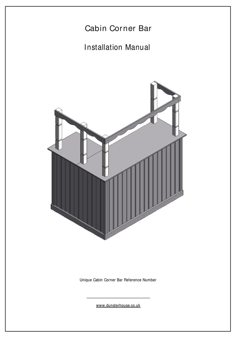
Dunster House Unique Cabin Corner Bar User manual

Dunster House

Dunster House Unique Cabin Corner Bar User manual

Dunster House P5-3030CORGAZ User manual

Dunster House

Dunster House P5-3030CORGAZ User manual

Dunster House H4-GS2X2MK2PRG User manual

Dunster House

Dunster House H4-GS2X2MK2PRG User manual

Dunster House ATLAS P5-3060PRG User manual

Dunster House

Dunster House ATLAS P5-3060PRG User manual

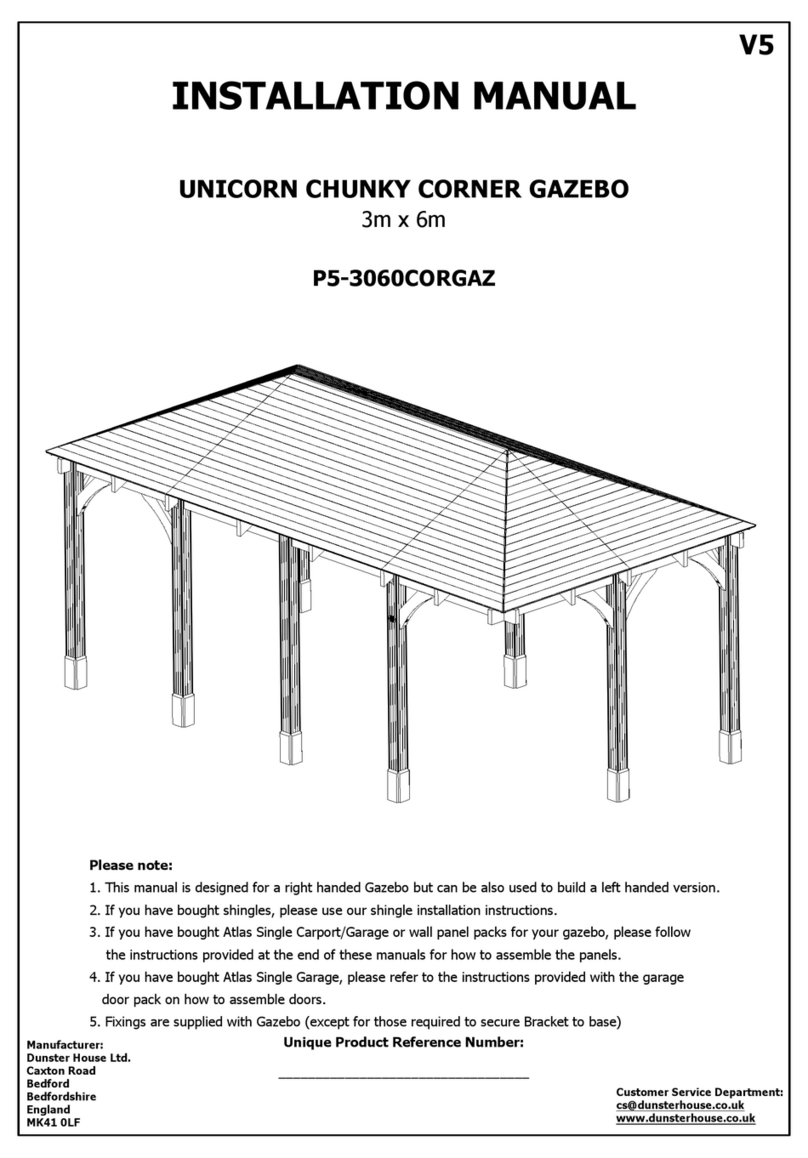
Dunster House P5-3060CORGAZ User manual

Dunster House

Dunster House P5-3060CORGAZ User manual

Dunster House P5-3030GAZAT User manual

Dunster House

Dunster House P5-3030GAZAT User manual

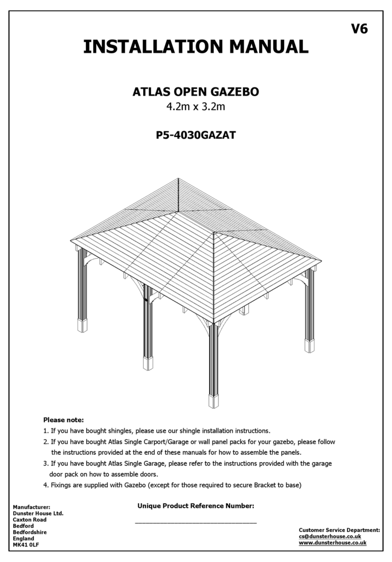
Dunster House ATLAS P5-4030GAZAT User manual

Dunster House

Dunster House ATLAS P5-4030GAZAT User manual

Dunster House H4-GS3X4PRG User manual

Dunster House

Dunster House H4-GS3X4PRG User manual

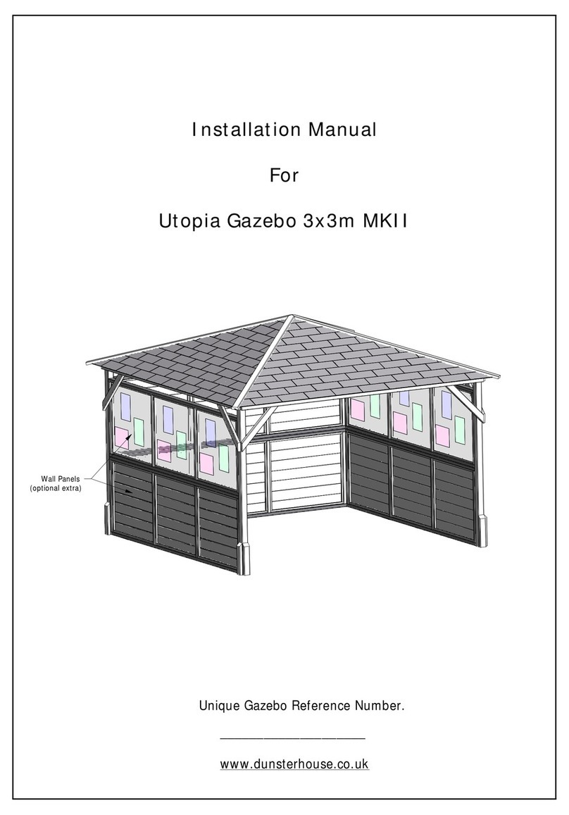
Dunster House Utopia 3x3m MKII User manual

Dunster House

Dunster House Utopia 3x3m MKII User manual

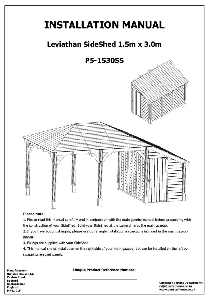
Dunster House Leviathan SideShed P5-1530SS User manual

Dunster House

Dunster House Leviathan SideShed P5-1530SS User manual

Dunster House P5-6030GAZAT User manual

Dunster House

Dunster House P5-6030GAZAT User manual

Dunster House P5-3050CANPRG User manual

Dunster House

Dunster House P5-3050CANPRG User manual

Dunster House Utopia 200 H3-GS2X2MK2 User manual

Dunster House

Dunster House Utopia 200 H3-GS2X2MK2 User manual

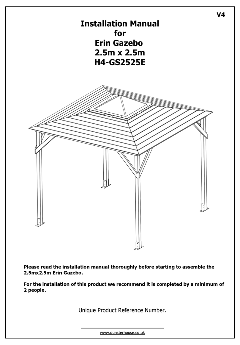
Dunster House Erin H4-GS2525E User manual

Dunster House

Dunster House Erin H4-GS2525E User manual

Dunster House Utopia User manual

Dunster House

Dunster House Utopia User manual

Dunster House Atlas User manual

Dunster House

Dunster House Atlas User manual
Dunster House Utopia 300 User manual

Dunster House

Dunster House Utopia 300 User manual

Popular Outdoor Furnishing manuals by other brands
Weka 662.1800.00.00 ASSEMBLY, USER AND MAINTENANCE INSTRUCTIONS

Weka

Weka 662.1800.00.00 ASSEMBLY, USER AND MAINTENANCE INSTRUCTIONS

Sunjoy A101005603 manual

Sunjoy

Sunjoy A101005603 manual

sweeek. VABO 10 WKDGCUBE10 manual

sweeek.

sweeek. VABO 10 WKDGCUBE10 manual

Alpine TEC294BZ manual

Alpine

Alpine TEC294BZ manual

Playcore ultra site 942P-R6 manual

Playcore

Playcore ultra site 942P-R6 manual

PHI VILLA 5PCS TABLE & CHAIRS Assembly instructions & user manual

PHI VILLA

PHI VILLA 5PCS TABLE & CHAIRS Assembly instructions & user manual

Safavieh PAT6717 Assembly instructions

Safavieh

Safavieh PAT6717 Assembly instructions

highwood Weatherly Assembly guide

highwood

highwood Weatherly Assembly guide

Kettler FORMA II 0104703-0600 Assembly & operating instructions

Kettler

Kettler FORMA II 0104703-0600 Assembly & operating instructions

Belson Outdoors PL6NB-P instruction sheet

Belson Outdoors

Belson Outdoors PL6NB-P instruction sheet

Hanover BCS01807 quick start guide

Hanover

Hanover BCS01807 quick start guide

Axley 017393 operating instructions

Axley

Axley 017393 operating instructions

John Lewis CAMDEN 820 07402 manual

John Lewis

John Lewis CAMDEN 820 07402 manual

Backyard Discovery BEAUMONT 2101555 manual

Backyard Discovery

Backyard Discovery BEAUMONT 2101555 manual

Yardistry SENECA PRIVACY ARBOR SPA8 YM14126 installation manual

Yardistry

Yardistry SENECA PRIVACY ARBOR SPA8 YM14126 installation manual

MASTERCANOPY GHG-041 Assembly and operating instructions

MASTERCANOPY

MASTERCANOPY GHG-041 Assembly and operating instructions

PlaySafe 22-PS302 owner's manual

PlaySafe

PlaySafe 22-PS302 owner's manual

ISLAND RETREAT NU6911 Assembly instructions

ISLAND RETREAT

ISLAND RETREAT NU6911 Assembly instructions

manuals.online logo
manuals.online logoBrands
  • About & Mission
  • Contact us
  • Privacy Policy
  • Terms and Conditions

Copyright 2025 Manuals.Online. All Rights Reserved.