manuals.online logo
Brands
  1. Home
  2. •
  3. Brands
  4. •
  5. Dunster House
  6. •
  7. Outdoor Furnishing
  8. •
  9. Dunster House P5-3050CANPRG User manual

Dunster House P5-3050CANPRG User manual

INSTALLATION MANUAL
P5-3050CANPRG
Leviathan Lean to Pergola 3.0m x 5.0m
Unique Product Reference Number:
__________________________________
Manufacturer:
Dunster House Ltd.
Caxton Road
Bedford
Bedfordshire
England
MK41 0LF
Customer Service Department:
cs@dunsterhouse.co.uk
www.dunsterhouse.co.uk
Please Note:
Fixings are supplied with your pergola (except the ones to secure the bracket to base and the
pergola to the wall).
Queries Procedure
Important Information
You will need
Please retain all documentation relating to your purchase.
In the unlikely event that you need to contact us, please do so in writing to:
Email: cs@dunsterhouse.co.uk
Post: Dunster House Ltd, Caxton Road, Elms Farm Industrial Estate, Bedford, MK41 0LF, England.
Our Customer Service department is open 9 a.m. to 5 p.m. Monday to Friday. Please include your Sales Order (SO)
number or post code in any correspondence with Customer Service to enable them to locate your file.
The Nature of Wood
The wood provided for your garden building is softwood which has been kiln dried and is pressure treated for
protection against fungal decay and insect infestation. Wood is a natural product which may have knots, knot holes,
imperfections, cracks and warping.
Due to the inherent properties of wood we make no guarantees with regards to the above, nor will replace any
lengths of timber for any of the following reasons:
•Any timber that contains knots where they do not influence the structural stability of the product.
•Cosmetic appearances - colour variations e.g. caused by the structure or age of the product.
•Timber that has shakes, cracks or gaps that do not influence the structural strength of the product.
•Any timber that has been covered or buried underground.
•Twisted timber that can be installed.
•Queries arising from a neglectful manner of construction be in the foundation or erection of the product.
•Queries due to modifications by the owner causing timber to deform.
Any valid queries will be satisfied by the exchange or replacement of the defective parts only.
Your building has been designed with the self build in mind. However, it is important that the assembly
instructions are followed carefully.
Precautions:
•Always use working gloves.
•It is essential to have an assistant.
•All screw holes need to be pre-drilled using a 3mm drill bit (not provided) to avoid timber splitting.
The Pergola is pressure treated so you will not need to treat it immediately or apply a preservative.
Pressure treatment does not mean that the timbers are waterproof, so you may wish to apply water repellent.
Water repellent can also be applied to timbers treated with a preservative.
Colour Transfer
This product has been pressure treated with wood preservative and a brown colour additive. Consideration should
be given to the propensity of the material to stain light colour adjacent surfaces, such as paving flags, render or
coated timber surfaces. We recommend contact between the timber and these surfaces is limited, and careful
consideration to storing the product prior to assembly should been taken in order to prevent such discolouration.
2 People Measuring Tape Spirit Level Drill/Driver
Gloves Ladder Hammer Utility Knife
Mallet Pozidriv bits 3mm Drill bit Saw
Socket Set Spanner 16mm Masonry Drill Bit (Wall panels only)
LNG_mmWIDTH_mmTHK_mmDESCRIPTIONPART NUMBERQTY
2260120120Post120x120x2260.A3
LNG_mm
WIDTH_mmTHK_mm
DESCRIPTION
PART NUMBER
QTY
2575140
45Beam
45x140x2575
4
LNG_mmWIDTH_mmTHK_mmDESCRIPTIONPART NUMBERQTY
313514045
Rafter
45x140x3135.A7
LNG_mmWIDTH_mmTHK_mmDESCRIPTIONPART NUMBERQTY
63014045Brace45x140x630.A4
Page 3
Components required for Leviathan Lean to Pergola 3.0m x 5.0m
PURLIN
LNG_mm THK_mm
WIDTH_mm
POST
THK_mm
WIDTH_mm
LNG_mm
RAFTER
THK_mm
WIDTH_mm
LNG_mm
BRACE
THK_mm
WIDTH_mm
LNG_mm
LNG_mmWIDTH_mmTHK_mmDESCRIPTIONPART NUMBERQTY
30012020Post Trim20x120x300.A12
FIXINGS PACKING LIST
DESCRIPTIONPART NUMBERQTY
C/SK Wood ScrewSCREW 100 mm19
C/SK Wood Screw35mm Screw152
Hexogon head wood screwsM10 x 120mm Hex head screw8
Circular WasherIFI 542 - 128
Simpson BracketH2.5 Bracket
11
L BracketL Bracket - 70x70x55
4
DH Logo Metal PlateDH Logo Metal Plate
1
Page 4
Components required for Leviathan Lean to Pergola 3.0m x 5.0m
POST TRIM WIDTH_mm THK_mm
LNG_mm
COMPONENTS REQUIRED
QTYPART NUMBER
245x140x2575
COMPONENTS REQUIRED
QTYPART NUMBER
245x140x2575
3120x120x2260.A
6SCREW 100 mm
Assembly Steps for Leviathan Lean-to Pergola 3.0m x 5.0m
** Avoid splitting timber parts by pre-drilling all screw holes **
Step 1:
Page 5
Step 2:
•Once the location of your building has been established, position and fix the beams to the
wall using screws and suitable rawlplugs (not supplied) in the position shown from
ground level.
2720
2720
45x140x2575
45x140x2575
WALL
WALL
•Fix beams to support posts. Ensure the beams overhang evenly on both sides of the posts.
Use the diagram below for reference.
120x120x2260.A
45x140x2575
2275
SCREW 100 mm
Even Overlap Even Overlap
120x120x2260.A
Rawlplugs and Screws
(Not Supplied)
45x140x2575
2275
Ensure the beams adjoin
in the centre of the post.
45x140x2575
COMPONENTS REQUIRED
QTYPART NUMBER
345x140x3135.A
3H2.5 Bracket
6SCREW 100 mm
3035mm Screw
COMPONENTS REQUIRED
QTYPART NUMBER
445x140x3135.A
8H2.5 Bracket
7SCREW 100 mm
8035mm Screw
Assembly Steps for Leviathan Lean-to Pergola 3.0m x 5.0m
** Avoid splitting timber parts by pre-drilling all screw holes **
Step 3:
Page 6
Step 4:
SCREW 100 mm
45x140x3135.A
45x140x3135.A
•Slot 3x roof rafters through the posts, then fix to wall support using H2.5 brackets and
35mm screws.
•Fix the rafters to the posts using 2x 100mm screws per rafter.
•Fix the remaining rafters to the beam and wall support using H2.5 brackets and
35mm screws, making sure the rafters are equally spaced. Use 100mm screws to
fix the rafters from top down to the wall support.
H2.5 Bracket
SCREW 100 mm
H2.5 Bracket
H2.5 Bracket
35mm Screw
45x140x3135.A
45x140x3135.A
120x120x2260.A
Wall support
purlins
EqualEqual
Equal
Equal
Equal
Equal
COMPONENTS REQUIRED
QTY
PART NUMBER
4
45x140x630.A
8IFI 542 - 12
8M10 x 120mm Hex head
screw
COMPONENTS REQUIRED
QTYPART NUMBER
1635mm Screw
4
L Bracket - 70x70x55
Assembly Steps for Leviathan Lean-to Pergola 3.0m x 5.0m
** Avoid splitting timber parts by pre-drilling all screw holes **
Step 5:
Page 7
Step 6:
•Fix 45x140x630.A onto support posts and beams shown on the diagrams below.
•Use 2x Hex Head screws and 2x washers per brace.
45x140x630.A
45x140x630.A
M10 x 120mm Hex head screw
120x120x2260.A
35mm Screw
L Bracket - 70x70x55
•Use 4x screws to secure each bracket to a post; then fix to the ground using suitable
ground anchors (not supplied).
120x120x2260.A
COMPONENTS REQUIRED
QTYPART NUMBER
1220x120x300.A
2635mm Screw
1
DH Logo Metal Plate
Assembly Steps for Leviathan Lean-to Pergola 3.0m x 5.0m
** Avoid splitting timber parts by pre-drilling all screw holes **
Step 7:
Page 8
20x120x300.A
35mm Screw
•Fix 4x Post Trims to the base of each post, use 2x 35mm screw per trim.
•Fix the DH logo metal plate in place using 2x screws.
35mm Screw
CONGRATULATIONS on your new Pergola!!!
DH Logo Metal Plate
INSTALLATION MANUAL
Additional Wall Panels
P5-3050CANPRG
Leviathan Lean to Pergola 3.0m x 5.0m
Please note:
1. These instructions will enable you to assemble additional wall panels to your building.
The configuration of the panels shown on the illustrations may vary from the product you have purchased.
2. For illustration purposes we have shown the 3 standard wall layout in theses instructions. You can mix and
match the panels as they are designed to work in any configuration.
3. Avoid splitting timber by pre-drilling ALL screw holes
IMPORTANT INFORMATION
Please remove component 45x140x630.A (Brace) and internal 20x120x300.A (Post Trim) if components
CP1 and or CP8 are being installed.
Panel CP1
Page 10
Panel CP2
Panel CP8
Additional Wall Panels - Pack may contain
Pressure Treated Pressure Treated
Pressure Treated
908 70
1035
908 85
2120
908
85
1065
Page 11
Additional Wall Panels - Components may contain
15x70x2120
Full Wall Panel Trim
15x70x1065
Half Wall Panel Trim
15x70x1035
Glass Wall Panel Trim
20x100x908
Glass Wall Panel Sill
2120
70
15
1065 15
70
1035
70
15
ACCESSORIES
Description QTY
35mm Screws for Trims Varies
60mm Screws for Panels Varies
M10x110mm Hex Head Bolt for Shield Anchors 2 per panel
M10x28mm Washers 2 per panel
M10 Shield Anchors 2 per panel
(Cut from full height trim)
908 20
100
1085 15
70
15x70x1085
Half Wall Panel Trim
Assembly Steps for Wall Options
Step 1.
Panel CP1
60mm Screws
M10x110 Bolts
M10 Shield Anchors
M10x28 Washers
Page 12
•Position the Panel CP1 between the Posts as shown in the diagram below.
•Join 2x Panel CP1, using 10x 60mm screws.
•Connect the two panels to the Posts using 5x 60mm screws per panel and to the Beams with 2x 60mm
screws per panel.
•Fix the panels into the concrete base by
drilling n16 holes 80mm deep (2 per panel)
and inserting the shield anchors into the
holes.
•Fix the panels by inserting M10x110mm
bolts and M10 washers and tighten until
secure.
View from inside
Panel
M10x110mm
bolt &washer
M10 shield anchor
(n16 hole 80mm deep required)
Concrete
Full height wall panels assembly
** Quantity of components will vary,
depending on your purchase.
20
120
120
2973
2733
2733
2973
Please Note:
•Fix the end panels first and space the centre panel between them (option to add sealant between the panel and
the post).
•There may be a gap between the panels, which is covered by the external and internal trims.
60mm Screw
Please Note:
•To fit the panels the braces have to be removed.
Assembly Steps for Wall Options
Step 2.
35mm Screws
15x70x2120 Trim
Page 13
•Fix 15x70x2120 Trims using 8x 35mm screws per trim on the outside of the wall panels.
•Fix 15x70x2120 Trims using 8x 35mm screws per trim on the inside of the wall panels.
•The Trims will cover the joints between the panels.
View from outside
Full height wall panels assembly
15x70x2120
35mm Screw
35mm Screw
15x70x2120
View from inside
Assembly Steps for Wall Options
Step 1.
Panel CP2
M10x28 Washers
M10x110 Bolts
M10 Shield Anchors
60mm Screws
Page 14
•Position the Panel CP2 between the Posts as shown in the diagram below. Join 2x Panel CP2 using 6x
60mm screws.
•Connect the two panels to the Posts using 3x 60mm screws per panel.
•Fix the panels into the concrete by drilling
n16 holes 80mm deep (2 per panel) and
inserting the shield anchors into the
holes.
•Fix the panels by inserting M10x110mm
bolts and M10 washers and tighten
until secure.
View from inside
Panel
M10x110mm
bolt &washer
M10 shield anchor
(n16 hole 80mm deep required)
Concrete
Half height wall panels assembly
2973
2733
2733
2973
120
120
20
Please Note:
•Fix the end panels first and space the centre panel between them (option to add sealant between the panel and
the post).
•There may be a gap between the panels, which is covered by the external and internal trims.
60mm Screw
** Quantity of components will vary,
depending on your purchase.
Assembly Steps for Wall Options
Step 2.
20x100x908
15x70x1065
15x70x1085
35mm Screws
Page 15
•Position 20x100x908 Sills on top of Panels CP2 so that they are flush with the panel frame from inside the
gazebo.
•Fix using 3x 35mm screws.
•Fix 15x70x1065 Trims using 6x 35mm screws per trim on the outside of the wall panels.
•Fix 15x70x1085 Trims using 6x 35mm screws per trim on the inside of the wall panels.
•The Trims will cover the joints between the panels.
View from outside
Half height wall panels assembly
View from inside
20x100x908
35mm Screw
15x70x1085
35mm Screw
35mm Screw
Assembly Steps for Wall Options
Step 1.
Panel CP8
35mm Screws
15x70x1035
60mm Screws
Page 16
•Remove the beading trims from one side of Panel CP8 frames.
•Position Panel CP8 on top of the Sills so that they are flush on the inside. Join the frames together with part
2x 60mm screws each panel.
View from inside
Window panels assembly
**Assemble half height wall panels according to
the instructions given on the previous pages.
•Position glass panes into the frames and re-fix Beading Trims into position (see Glass
Installation page).
•Position 15x70x1035 Window Trim in the centre of two window panels (outside) and
secure with 35mm screws.
•Position 15x70x1035 Window Trim in the centre of two window panels (inside) and
secure with 35mm screws.
15x70x1035
35mm Screw
60mm Screw
15x70x1035
35mm Screw
View from outside
Please Note:
•To fit the glass panel the
braces have to be removed.
View from
inside
Assembly Steps for Wall Options
40mm Pin Nail
12x
19x25x840
2x
19x25x9152x
4x825x960 TGLASS
1x
Page 17
Step 1:
Place 4x825x960 TGLASS into panel frame and make sure
it is centralized.
Once the glass is in place, apply silicone around the glass to
secure it into place.
Silicone
Silicone
Silicone
Silicone
Step 2:
Fix 2x 19x25x840 and 2x 19x25x915 parallel with their counterparts and secure using 40mm pin nails into per
timber as shown in the image below.
Place silicone around the edge of the frame.
Silicone
Silicone
Silicone
Silicone
Step 4:
Please note:
The glass is a smaller size compared to
panel frame to compensate for timbers
contracting, swelling and glass not being
cut square.
Step 3: Pre-drill the holes for the pin nails into the following
glass beading:
2x 19x25x840
2x 19x25x915
19x25x840.A
19x25x915
PIN NAIL 40 mm
PIN NAIL 40 mm

Other Dunster House Outdoor Furnishing manuals
Dunster House H3-GS3X4 User manual

Dunster House

Dunster House H3-GS3X4 User manual

Dunster House Utopia User manual

Dunster House

Dunster House Utopia User manual

Dunster House Utopia 3x3m MKII User manual

Dunster House

Dunster House Utopia 3x3m MKII User manual

Dunster House P5-6030GAZAT User manual

Dunster House

Dunster House P5-6030GAZAT User manual

Dunster House P5-3030CORGAZ User manual

Dunster House

Dunster House P5-3030CORGAZ User manual

Dunster House Unique Cabin Corner Bar User manual

Dunster House

Dunster House Unique Cabin Corner Bar User manual

Dunster House H4-GS3X4PRG User manual

Dunster House

Dunster House H4-GS3X4PRG User manual

Dunster House ATLAS P5-4030GAZAT User manual

Dunster House

Dunster House ATLAS P5-4030GAZAT User manual

Dunster House P5-3030CANGAZ User manual

Dunster House

Dunster House P5-3030CANGAZ User manual

Dunster House H4-GS2X2MK2PRG User manual

Dunster House

Dunster House H4-GS2X2MK2PRG User manual

Dunster House Leviathan SideShed P5-1530SS User manual
Dunster House

Dunster House Leviathan SideShed P5-1530SS User manual

Dunster House Leviathan P5-4040GAZAT User manual

Dunster House

Dunster House Leviathan P5-4040GAZAT User manual

Dunster House Erin H4-GS2525E User manual

Dunster House

Dunster House Erin H4-GS2525E User manual

Dunster House P5-3030GAZAT User manual
Dunster House

Dunster House P5-3030GAZAT User manual

Dunster House ATLAS P5-3060PRG User manual

Dunster House

Dunster House ATLAS P5-3060PRG User manual

Dunster House Atlas User manual

Dunster House

Dunster House Atlas User manual

Dunster House P5-3060CORGAZ User manual
Dunster House

Dunster House P5-3060CORGAZ User manual

Dunster House Utopia 300 User manual

Dunster House

Dunster House Utopia 300 User manual

Dunster House Utopia 200 H3-GS2X2MK2 User manual
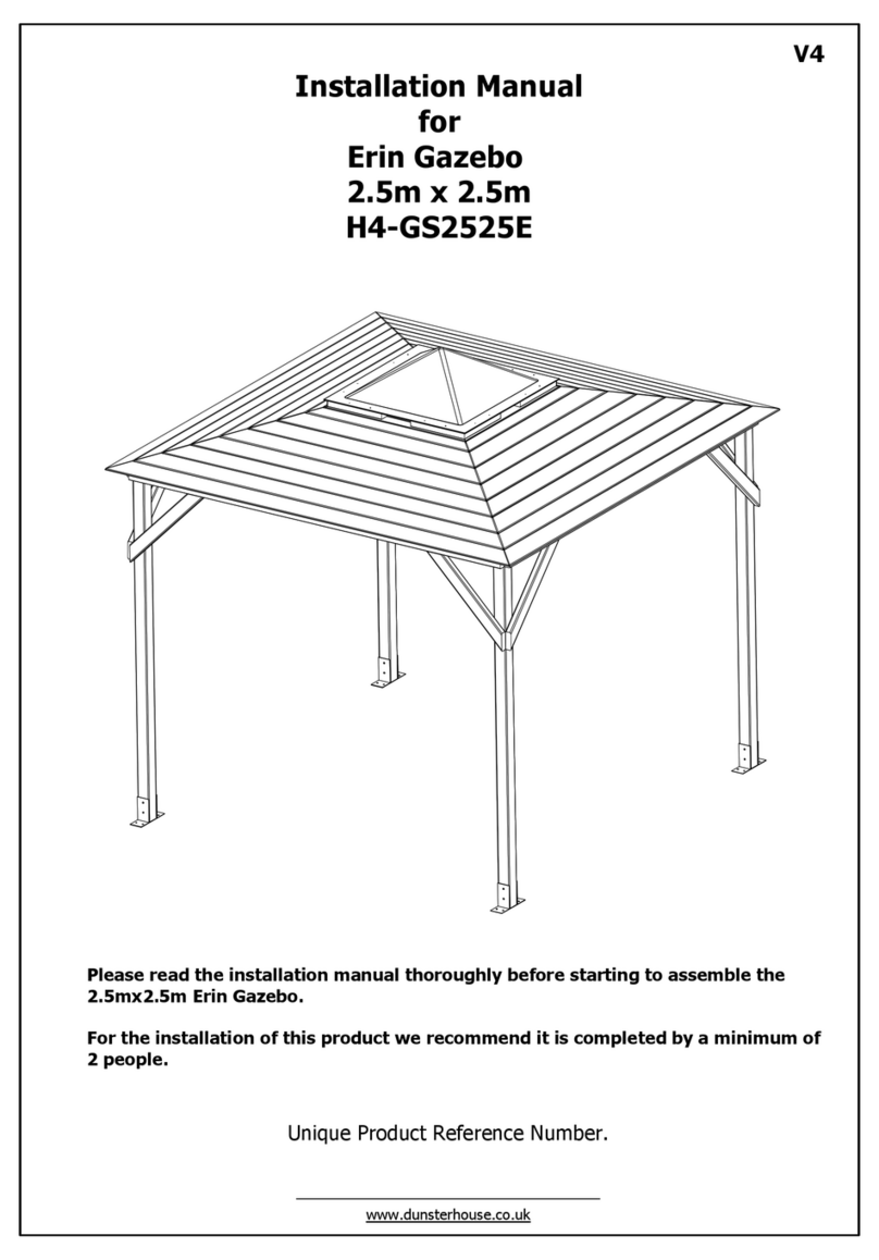
Dunster House

Dunster House Utopia 200 H3-GS2X2MK2 User manual

Popular Outdoor Furnishing manuals by other brands
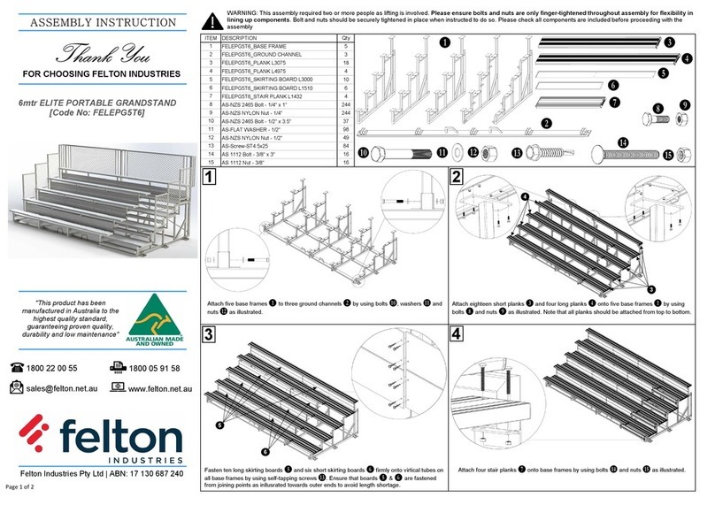
Anova D1007 Assembly instructions

Anova

Anova D1007 Assembly instructions

Sunjoy D-SC002PAL ASSEMBLY INTRUCTION

Sunjoy

Sunjoy D-SC002PAL ASSEMBLY INTRUCTION

Dragon Wholesaling Family EVO installation instructions

Dragon Wholesaling

Dragon Wholesaling Family EVO installation instructions

Lippert 3000 Series installation manual

Lippert

Lippert 3000 Series installation manual

PatioTree 970341 manual

PatioTree

PatioTree 970341 manual

hanit TAUNUS Assembly instructions

hanit

hanit TAUNUS Assembly instructions

FUJIEI Nychair X Assembly and instruction manual

FUJIEI

FUJIEI Nychair X Assembly and instruction manual

HOMCOM 831-337V04 manual

HOMCOM

HOMCOM 831-337V04 manual

RioOutdoors 4S-SH installation instructions

RioOutdoors

RioOutdoors 4S-SH installation instructions

Stansport 615 instructions

Stansport

Stansport 615 instructions

Costco 1452582 manual

Costco

Costco 1452582 manual

Jaclyn Smith 0-05531020-5 Use and care guide

Jaclyn Smith

Jaclyn Smith 0-05531020-5 Use and care guide

Alpine HEH210 owner's manual

Alpine

Alpine HEH210 owner's manual

KNOBLOCH FLASH DB7010 Mounting instructions

KNOBLOCH

KNOBLOCH FLASH DB7010 Mounting instructions

Dancover PA152005 manual

Dancover

Dancover PA152005 manual

Country Living 80267 owner's manual

Country Living

Country Living 80267 owner's manual

Breezesta PB-1600 Assembly

Breezesta

Breezesta PB-1600 Assembly

Sunjoy L-GZ375PST Assembly instructions

Sunjoy

Sunjoy L-GZ375PST Assembly instructions

manuals.online logo
manuals.online logoBrands
  • About & Mission
  • Contact us
  • Privacy Policy
  • Terms and Conditions

Copyright 2025 Manuals.Online. All Rights Reserved.