manuals.online logo
Brands
  1. Home
  2. •
  3. Brands
  4. •
  5. Dunster House
  6. •
  7. Outdoor Furnishing
  8. •
  9. Dunster House P5-3030CANGAZ User manual

Dunster House P5-3030CANGAZ User manual

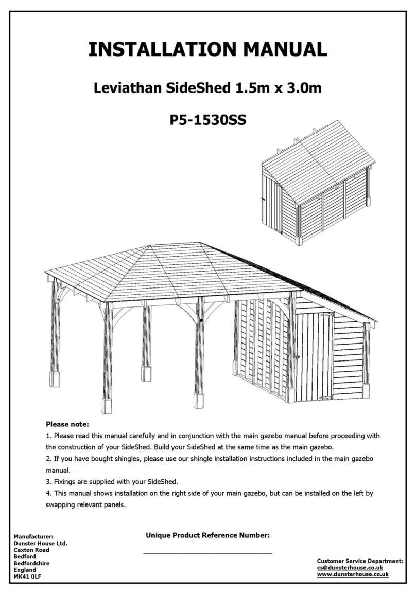
INSTALLATION MANUAL
Leviathan Canopy Gazebo 3.0m x 3.0m
P5-3030CANGAZ
Unique Product Reference Number:
__________________________________
Manufacturer:
Dunster House Ltd.
Caxton Road
Bedford
Bedfordshire
England
MK41 0LF
Customer Service Department:
cs@dunsterhouse.co.uk
www.dunsterhouse.co.uk
Please note:
1. If you have bought shingles, please use our shingle installation instructions.
2. Fixings are supplied with Gazebo (except those required to secure bracket to base and to secure the
gazebo to your wall).
Queries Procedure
Important Information
You will need
Please retain all documentation relating to your purchase.
In the unlikely event that you need to contact us, please do so in writing to:
Email: cs@dunsterhouse.co.uk
Post: Dunster House Ltd, Caxton Road, Elms Farm Industrial Estate, Bedford, MK41 0LF, England.
Our Customer Service department is open 9 a.m. to 5 p.m. Monday to Friday. Please include your Sales Order (SO)
number or post code in any correspondence with Customer Service to enable them to locate your file.
The Nature of Wood
The wood provided for your garden building is softwood which has been kiln dried and is pressure treated for
protection against fungal decay and insect infestation. Wood is a natural product which may have knots, knot holes,
imperfections, cracks and warping.
Due to the inherent properties of wood we make no guarantees with regards to the above, nor will replace any
lengths of timber for any of the following reasons:
•Any timber that contains knots where they do not influence the structural stability of the product.
•Cosmetic appearances - colour variations e.g. caused by the structure or age of the product.
•Timber that has shakes, cracks or gaps that do not influence the structural strength of the product.
•Any timber that has been covered or buried underground.
•Twisted timber that can be installed.
•Queries arising from a neglectful manner of construction be in the foundation or erection of the product.
•Queries due to modifications by the owner causing timber to deform.
Any valid queries will be satisfied by the exchange or replacement of the defective parts only.
Your Gazebo has been designed with the self build in mind. However, it is important that the assembly
instructions are followed carefully.
Precautions:
•Always use working gloves.
•It is essential to have an assistant.
•All screw holes need to be pre-drilled using a 3mm drill bit (not provided) to avoid timber splitting.
The Gazebo is pressure treated so you will not need to treat it immediately or apply a preservative.
Pressure treatment does not mean that the timbers are waterproof, so you may wish to apply water repellent.
Water repellent can also be applied to timbers treated with a preservative.
Colour Transfer
This product has been pressure treated with wood preservative and a brown colour additive. Consideration should
be given to the propensity of the material to stain light colour adjacent surfaces, such as paving flags, render or
coated timber surfaces. We recommend contact between the timber and these surfaces is limited, and careful
consideration to storing the product prior to assembly should been taken in order to prevent such discolouration.
2 People Measuring Tape Spirit Level Drill/Driver
Gloves Ladder Hammer Utility Knife
Mallet Pozidriv bits 3mm Drill bit Saw
Socket Set Spanner 16mm Masonry Drill Bit (Wall panels only)
LNG_mmWIDTH_mmTHK_mmDESCRIPTIONPART NUMBERQTY
2260120120Post120x120x2260.A2
LNG_mmWIDTH_mmTHK_mmDESCRIPTIONPART NUMBERQTY
16009519Roof BoardF.160068
LNG_mm
WIDTH_mmTHK_mm
DESCRIPTION
PART NUMBER
QTY
16004019Roof BoardF.4016002
LNG_mmWIDTH_mmTHK_mmDESCRIPTIONPART NUMBERQTY
32007019Fascia19x70x32001
Page 3
Components required for Leviathan Canopy Gazebo 3.0m x 3.0m
POST
THK_mm
WIDTH_mm
LNG_mm
ROOF BOARD
LNG_mm THK_mm
WIDTH_mm
ROOF BOARD
THK_mm
WIDTH_mm
LNG_mm
FASCIA
LNG_mm THK_mm
WIDTH_mm
LNG_mmWIDTH_mmTHK_mmDESCRIPTIONPART NUMBERQTY
31407019Fascia19x70x3140.A2
LNG_mmWIDTH_mmTHK_mmDESCRIPTIONPART NUMBERQTY
31003535
Roof Trim
35x35x31002
LNG_mm
WIDTH_mmTHK_mm
DESCRIPTION
PART NUMBER
QTY
30012020
Post Trim
20x120x300.A8
LNG_mmWIDTH_mmTHK_mmDESCRIPTIONPART NUMBERQTY
320014045Beam45x140x32002
Page 4
Components required for Leviathan Canopy Gazebo 3.0m x 3.0m
FASCIA
LNG_mm
WIDTH_mm
THK_mm
POST TRIM WIDTH_mm THK_mm
LNG_mm
ROOF TRIM
THK_mm
WIDTH_mm
LNG_mm
PURLIN
LNG_mm THK_mm
WIDTH_mm
LNG_mm
WIDTH_mmTHK_mm
DESCRIPTION
PART NUMBER
QTY
630140
45Brace
45x140x630.A2
LNG_mmWIDTH_mmTHK_mmDESCRIPTIONPART NUMBERQTY
313514045Rafter45x140x3135.A5
FIXINGS PARTS LIST
DESCRIPTIONPART NUMBERQTY
Shank NailsNail 40mm
210
C/SK Wood Screw
SCREW 100 mm13
C/SK Wood Screw
35mm Screw151
Hexogon head wood screwsM10 x 120mm Hex head screw
4
Circular Washer
IFI 542 - 124
Simpson BracketH2.5 Bracket
8
L BracketL Bracket - 70x70x552
DH Logo Metal PlateDH Logo Metal Plate1
Page 5
Components required for Leviathan Canopy Gazebo 3.0m x 3.0m
RAFTER
THK_mm
WIDTH_mm
LNG_mm
BRACE
THK_mm
WIDTH_mm
LNG_mm
COMPONENTS REQUIRED
PART NUMBERQTY
45x140x32001
COMPONENTS REQUIRED
PART NUMBERQTY
120x120x2260.A2
45x140x32001
SCREW 100 mm4
Assembly Steps for Leviathan Canopy Gazebo 3.0m x 3.0m
** Avoid splitting timber parts by pre-drilling all screw holes **
Step 1:
Page 6
Step 2:
•Once the location of your building has been established, position and fix 1x 45x140x3200 to the wall
using screws and suitable rawlplugs (not supplied) in the position shown from ground level.
•Position and fix 1x 45x140x3200 to 2x 120x120x2260.A using 2x 100mm screw per post.
45x140x3200
2720
WALL
WALL
45x140x3200
2720
Equal
120x120x2260.A120x120x2260.A
45x140x3200
Equal
Wall fixings
(not supplied)
2725
SCREW 100 mm
SCREW 100 mm
SCREW 100 mm
COMPONENTS REQUIRED
PART NUMBERQTY
45x140x3135.A5
SCREW 100 mm9
35mm Screw80
H2.5 Bracket8
Assembly Steps for Leviathan Canopy Gazebo 3.0m x 3.0m
** Avoid splitting timber parts by pre-drilling all screw holes **
Step 3:
Page 7
•Position and fix 2x 45x140x3135.A using 1x H2.5 Bracket, 10x 35mm screw and 2x 100mm screw
per rafter as shown below.
45x140x3135.A
45x140x3135.A
H2.5 Bracket
35mm Screw
•Position and fix the remaining 3x 45x140x3135.A rafters using 2x H2.5 Brackets and 20x 35mm screw per rafter.
•Ensure the rafters are evenly spaced when fixing.
•Fix the rafters to the wall support purlin using 1x 100mm screw per rafter, as shown.
SCREW 100 mm
EqualEqualEqualEqual
H2.5 Bracket
H2.5 Bracket
SCREW 100 mm
45x140x3135.A
Wall support
purlin
COMPONENTS REQUIRED
PART NUMBER
QTY
45x140x630.A2
35mm Screw8
M10 x 120mm and M10
washer
4
L Bracket - 70x70x55
2
COMPONENTS REQUIRED
PART NUMBERQTY
F.160068
F.4016002
Nail 40mm210
Assembly Steps for Leviathan Canopy Gazebo 3.0m x 3.0m
** Avoid splitting timber parts by pre-drilling all screw holes **
Step 4:
Page 8
Step 5:
•Fix 2x 45x140x630.A using 2x M10 120mm hex head screw and 2x M10 washer per brace.
•Fix 2x L bracket to the posts; using 4x35mm screw per bracket and to the ground (fixings not supplied).
L Bracket - 70x70x55
35mm Screw
45x140x630.A
M10 x 120mm and M10 washer
•Fix 68x F.1600 and 2x F.401600 to the rafters using 3x Nail 40mm per roof board.
•Ensure you leave a 2mm expansion gap in between roof boards.
Nail 40mm
F.1600
F.1600
F.401600
45x140x630.A
COMPONENTS REQUIRED
PART NUMBER
QTY
19x70x32001
19x70x3140.A2
35x35x31002
35mm Screw45
Assembly Steps for Leviathan Canopy Gazebo 3.0m x 3.0m
** Avoid splitting timber parts by pre-drilling all screw holes **
Step 6:
Page 9
35x35x3100
35x35x3100
35mm Screw
•Fix 2x 35x35x3100 to the roof boards, using 10x 35mm screw per trim as shown.
•Fix 2x 19x70x3140.A to the roof trim, using 10x 35mm screw per
fascia.
•Fix 1x 19x70x3100 using 5x 35mm screw, 1 screw per rafter join.
Please note:
If you have ordered felt or shingles, refer to the Felt Installation or Shingle
Installation page before installing your fascia.
19x70x3140.A
19x70x3200
19x70x3140.A
35mm Screw
35mm Screw
35mm Screw
35mm Screw
35x35x3100
COMPONENTS REQUIRED
PART NUMBER
QTY
20x120x300.A
8
35mm Screw18
DH Logo Metal Plate
1
Assembly Steps for Leviathan Canopy Gazebo 3.0m x 3.0m
** Avoid splitting timber parts by pre-drilling all screw holes **
Step 7:
Page 10
•Fix 4x 20x120x300.A to each post, using 2x 35mm screw per post trim.
•Fix 1x DH Logo Metal Plate to the front post using 2x 35mm screw as shown.
CONGRATULATIONS on your new Canopy Gazebo!
20x120x300.A
20x120x300.A
35mm Screw
35mm Screw
DH Logo Metal Plate
35mm Screw
Felt Instructions Page 11
•Fully cover the roof boards with the plastic
waterproof membrane, overhanging the roof
boards by a minimum of 30mm.
•We suggest to fix it using a staple gun.
Waterproof membrane
•Place and fix the first row of felt over the top
of the waterproof membrane, overhanging the
roof by a minimum of 40-50mm and spacing
clout nails approximately 200mm apart.
•Trim off any excess at the end of the row,
reusing offcuts where possible.
•Lay a second layer of felt on top of the first
row. Ensure the second layer overlaps the first
by a minimum of 200mm.
•Trim off any excess at the end of the row,
reusing offcuts where possible.
•Continue to lay felt in rows, overlapping each
row by a minimum of 200mm until you have
reached the end of the roof.
•Where the felt meets the wall, locate
the mortar in between the bricks
directly above the canopy gazebo.
•Remove the mortar to a depth of
approximately 20mm for the whole
length of the canopy gazebo.
•Insert the lead flashing (not supplied)
into the mortar aperture and form the
lead to match the wall and roof
profile.
•Once you have formed the lead,
secure it into position by using fresh
mortar or silicone.
•When your felt is fully installed,
continue by fixing your fascia.
Please note:
These images are used for reference only and may differ from your structure in size and/or orientation.
First layer of
felt, overhang
by a minimum
of 40-50mm.
Second layer of
felt. Ensure sheets
overlap by a
minimum of 200mm.
Lead
flashing
Shingle Instructions Page 12
•Fully cover the roof boards with the plastic
waterproof membrane, overhanging the roof
boards by a minimum of 30mm.
•We suggest to fix it using a staple gun.
Waterproof membrane
•Place and fix the first row of shingles over the
top of the waterproof membrane with the slots
running upwards, overhanging the roof by
40-50mm and using 4 clout nails per shingle.
•Trim off any excess at the end of the row,
reusing offcuts where possible.
•Lay a second layer of shingles on top of the
first row. Rotate this layer of shingles by 180°
so that the slots are running downwards.
•Trim off any excess at the end of the row,
reusing offcuts where possible.
•Continue to lay shingles in rows offset and
overlapping each row until you have reached
the end of the roof.
•Where the shingles meet the wall,
locate the mortar in between the
bricks directly above the canopy
gazebo.
•Remove the mortar to a depth of
approximately 20mm for the whole
length of the canopy gazebo.
•Insert the lead flashing (not supplied)
into the mortar aperture and form the
lead to match the wall and roof
profile.
•Once you have formed the lead,
secure it into position by using fresh
mortar or silicone.
•When your shingles are fully installed,
continue by fixing your fascia.
First layer of
shingles with
slots facing up
Second layer of
shingles with slots
facing down
Lead
flashing
Please note:
These images are used for reference only and may differ from your structure in size and/or orientation.
Guttering without water butt
Fig.D
Guttering with water butt
Fig.A
Fig.C
Fig.B
Fig.E
Guttering Installation Page 13
Running outlet
Gutter union
Stop end
Pipe Shoe Water
butt
Pipe Elbow
Downpipe bracket
Downpipe
sections
Elbow
pieces
Downpipe
Downpipe
bracket
Support
bracket
•Screw the running outlet to the fascia, ensuring the
downpipe will be in line with your post (Fig.A).
•Fix the support brackets to the fascia using two screws per
bracket and ensuring spacing of 400-600mm between each
support bracket (Fig.B).
•Slot one piece of guttering into the gutter union and then fix
to the fascia with one screw, ensuring that there is 1
degree of fall towards the running outlet to allow the
guttering to drain.
•Connect the next gutter section to the second union and
click this assembly into the first union and screw to the
fascia (Fig.C).
•Continue adding sections of guttering to fit the length of
your canopy gazebo, repeating the previous steps and
finish off by connecting the stop end to the last section of
gutter, trimming the guttering to the correct length where
necessary.
•The stop end should finish approximately flush with the end
of the fascia (Fig.D).
•Join together sections of downpipe and elbow pieces to
desired length, finishing with a shoe piece (ignore this step
if installing a water butt).
•To install the water butt, connect the downpipe sections and
elbow pieces to the running outlet and position the water
butt below the downpipe, with the lid removed.
•Mark and trim the downpipe so it extends into the water
butt by approximately 150mm.
•Note - the hole in the water butt lid will need to be cut out
to match the diameter of the downpipe.
•Once all the guttering components have been positioned
correctly screw the downpipe brackets to the canopy
gazebo post (Fig.E).
INSTALLATION MANUAL
Additional Wall Panels
Please note:
1. These instructions will enable you to assemble additional wall panels to your building.
The configuration of the panels shown on the illustrations may vary from the product you have purchased.
2. For illustration purposes we have shown the 3 standard wall layout in theses instructions. You can mix and
match the panels as they are designed to work in any configuration.
3. Avoid splitting timber by pre-drilling ALL screw holes.
IMPORTANT INFORMATION
Please remove component 45x140x630.A (Brace) and internal 20x120x300.A (Post Trim)
if components CP1 and or CP8 are being installed.
Panel CP1 Panel CP2
Panel CP8
Additional Wall Panels- Pack may contain
Pressure Treated Pressure Treated
Pressure Treated
Page 15
908 70
1035
908 85
2120
908
85
1065
Additional Wall Panels- Pack may contain
15x70x2120
Full Wall Panel Trim
15x70x1065
Half Wall Panel Trim
15x70x1035
Glass Wall Panel Trim
20x100x908
Glass Wall Panel Sill
Page 16
2120
70
15
1065 15
70
1035
70
15
ACCESSORIES
Description QTY
35mm Screws for Trims Varies
60mm Screws for Panels Varies
M10x110mm Hex Head Bolt for Shield Anchors 2 per panel
M10x28mm Washers 2 per panel
M10 Shield Anchors 2 per panel
(Cut from full height trim)
908 20
100
1085 15
70
15x70x1085
Half Wall Panel Trim
Assembly Steps for Wall Options
Step 1.
Panel CP1
60mm Screws
M10x110 Bolts
M10 Shield Anchors
M10x28 Washers
Page 17
•Position the Panel CP1 between the Posts as shown in the diagram below.
•Join 2x Panel CP1, using 10x 60mm screws.
•Connect the two panels to the Posts using 5x 60mm screws per panel and to the Beams with 2x 60mm
screws per panel.
•Fix the panels into the concrete base by
drilling n16 holes 80mm deep (2 per panel)
and inserting the shield anchors into the
holes.
•Fix the panels by inserting M10x110mm
bolts and M10 washers and tighten until
secure.
View from inside
Panel
M10x110mm
bolt &washer
M10 shield anchor
(n16 hole 80mm deep required)
Concrete
Full height wall panels assembly
** Quantity of components will vary,
depending on your purchase.
20
120
120
2965
2725
2725
2965
Please Note:
•Fix the end panels first and space the centre panel between them (option to add sealant between the panel and
the post).
•There may be a gap between the panels, which is covered by the external and internal trims.
60mm Screw
Please Note:
•To fit the panels the braces have to be removed.
Assembly Steps for Wall Options
Step 2.
35mm Screws
15x70x2120 Trim
Page 18
•Fix 15x70x2120 Trims using 8x 35mm screws per trim on the outside of the wall panels.
•Fix 15x70x2120 Trims using 8x 35mm screws per trim on the inside of the wall panels.
•The Trims will cover the joints between the panels.
View from outside
Full height wall panels assembly
15x70x2120
35mm Screw
35mm Screw
15x70x2120
View from inside
Assembly Steps for Wall Options
Step 1.
Panel CP2
M10x28 Washers
M10x110 Bolts
M10 Shield Anchors
60mm Screws
Page 19
•Position the Panel CP2 between the Posts as shown in the diagram below. Join 2x Panel CP2 using 6x
60mm screws.
•Connect the two panels to the Posts using 3x 60mm screws per panel.
•Fix the panels into the concrete by drilling
n16 holes 80mm deep (2 per panel) and
inserting the shield anchors into the
holes.
•Fix the panels by inserting M10x110mm
bolts and M10 washers and tighten
until secure.
View from inside
Panel
M10x110mm
bolt &washer
M10 shield anchor
(n16 hole 80mm deep required)
Concrete
Half height wall panels assembly
2965
2725
2725
2965
120
120
20
Please Note:
•Fix the end panels first and space the centre panel between them (option to add sealant between the panel and
the post).
•There may be a gap between the panels, which is covered by the external and internal trims.
60mm Screw
** Quantity of components will vary,
depending on your purchase.
Assembly Steps for Wall Options
Step 2.
20x100x908
15x70x1065
15x70x1085
35mm Screws
Page 20
•Position 20x100x908 Sills on top of Panels CP2 so that they are flush with the panel frame from inside the
gazebo.
•Fix using 3x 35mm screws.
•Fix 15x70x1065 Trims using 6x 35mm screws per trim on the outside of the wall panels.
•Fix 15x70x1085 Trims using 6x 35mm screws per trim on the inside of the wall panels.
•The Trims will cover the joints between the panels.
View from outside
Half height wall panels assembly
View from inside
20x100x908
35mm Screw
15x70x1085
35mm Screw
35mm Screw

Other Dunster House Outdoor Furnishing manuals
Dunster House H3-GS3X4 User manual

Dunster House

Dunster House H3-GS3X4 User manual

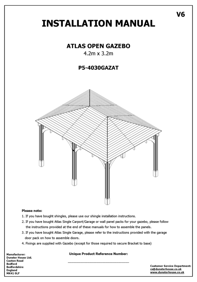
Dunster House ATLAS P5-4030GAZAT User manual

Dunster House

Dunster House ATLAS P5-4030GAZAT User manual

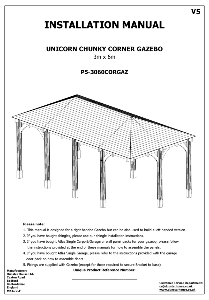
Dunster House P5-3030CORGAZ User manual

Dunster House

Dunster House P5-3030CORGAZ User manual

Dunster House Utopia 300 User manual

Dunster House

Dunster House Utopia 300 User manual

Dunster House Utopia 3x3m MKII User manual

Dunster House

Dunster House Utopia 3x3m MKII User manual

Dunster House Utopia 200 H3-GS2X2MK2 User manual

Dunster House

Dunster House Utopia 200 H3-GS2X2MK2 User manual

Dunster House ATLAS P5-3060PRG User manual

Dunster House

Dunster House ATLAS P5-3060PRG User manual

Dunster House Leviathan P5-4040GAZAT User manual
Dunster House

Dunster House Leviathan P5-4040GAZAT User manual

Dunster House P5-3060CORGAZ User manual

Dunster House

Dunster House P5-3060CORGAZ User manual

Dunster House P5-3030GAZAT User manual

Dunster House

Dunster House P5-3030GAZAT User manual

Dunster House Unique Cabin Corner Bar User manual
Dunster House

Dunster House Unique Cabin Corner Bar User manual

Dunster House P5-6030GAZAT User manual

Dunster House

Dunster House P5-6030GAZAT User manual

Dunster House H4-GS3X4PRG User manual

Dunster House

Dunster House H4-GS3X4PRG User manual

Dunster House Utopia User manual

Dunster House

Dunster House Utopia User manual

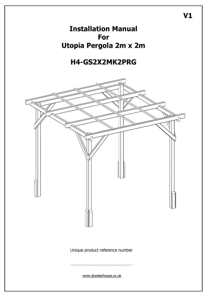
Dunster House H4-GS2X2MK2PRG User manual
Dunster House

Dunster House H4-GS2X2MK2PRG User manual

Dunster House Atlas User manual

Dunster House

Dunster House Atlas User manual

Dunster House P5-3050CANPRG User manual

Dunster House

Dunster House P5-3050CANPRG User manual

Dunster House Erin H4-GS2525E User manual
Dunster House

Dunster House Erin H4-GS2525E User manual

Dunster House Leviathan SideShed P5-1530SS User manual

Dunster House

Dunster House Leviathan SideShed P5-1530SS User manual

Popular Outdoor Furnishing manuals by other brands
Sunjoy L-GG001PST-F Assembly instruction

Sunjoy

Sunjoy L-GG001PST-F Assembly instruction

vita The Fairfield Arbor Assembly instructions

vita

vita The Fairfield Arbor Assembly instructions

BENITO Urban Odette H413 Anchoring instructions

BENITO

BENITO Urban Odette H413 Anchoring instructions

BENITO Mielek R Anchoring instructions

BENITO

BENITO Mielek R Anchoring instructions

Yardistry YM12837 Installation and operating instructions

Yardistry

Yardistry YM12837 Installation and operating instructions

Sunjoy A102007700 Assembly instruction

Sunjoy

Sunjoy A102007700 Assembly instruction

Palram SideWall 3 Assembly instructions

Palram

Palram SideWall 3 Assembly instructions

belavi GRILL GAZEBO user manual

belavi

belavi GRILL GAZEBO user manual

Home Decorators Collection NAPLES FRS00481BF-ST Use and care guide

Home Decorators Collection

Home Decorators Collection NAPLES FRS00481BF-ST Use and care guide

Lifetime GLIDER 60361 Assembly instructions

Lifetime

Lifetime GLIDER 60361 Assembly instructions

Polhus Pavilion Ines P3838 Assembly instructions

Polhus

Polhus Pavilion Ines P3838 Assembly instructions

Hanover Traditions TRAD5PCFPBR-RED Assembly instructions

Hanover

Hanover Traditions TRAD5PCFPBR-RED Assembly instructions

Jack-Post JPC-801-JE Use and care guide

Jack-Post

Jack-Post JPC-801-JE Use and care guide

Verano RIVA V920 installation manual

Verano

Verano RIVA V920 installation manual

Canvas 088-2279-8 Assembly instructions

Canvas

Canvas 088-2279-8 Assembly instructions

Seaside Casual 601 Assembly instructions

Seaside Casual

Seaside Casual 601 Assembly instructions

Essential Garden Mission Creek Use and care guide

Essential Garden

Essential Garden Mission Creek Use and care guide

Kettler Charlbury 0195536-6009 Assembly instructions

Kettler

Kettler Charlbury 0195536-6009 Assembly instructions

manuals.online logo
manuals.online logoBrands
  • About & Mission
  • Contact us
  • Privacy Policy
  • Terms and Conditions

Copyright 2025 Manuals.Online. All Rights Reserved.