Dyness B4850 User manual

B4850 ESS Unit
Operation Manual
TM012 Rev. 003

2
Sommario
Statement of Law .....................................................................................................4
1.0 Safety ...............................................................................................................6
1.1 SkillsofQualiedPersonnel .....................................................................6
1.2 Symbols ....................................................................................................6
1.3 BeforeConnecting ....................................................................................8
1.4 Inusing......................................................................................................9
1.5 Safehandlingoflithiumbatteriesguide ....................................................9
1.5.1 Schematicdiagramofsolution.......................................................9
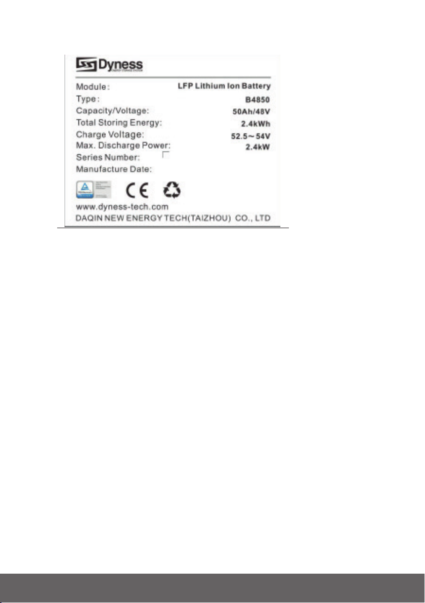
1.6 Productidentitydenition........................................................................10
2.0 Introduction ...................................................................................................12
2.1 BriefIntroduction.....................................................................................12
2.2 ProductProperties ..................................................................................12
2.3 Systemparameter...................................................................................13
2.4 InterfaceDenition ..................................................................................14
2.4.1 DIPswitchdenitionanddescription ...........................................15
2.5 BatteryManagementSystem(BMS).......................................................18
2.5.1 VoltageProtection........................................................................18
2.5.2 CurrentProtection........................................................................18
2.5.3 TemperatureProtection ...............................................................18
2.5.4 OtherProtection..........................................................................18
3.0 Installation .....................................................................................................19
3.1 Tools........................................................................................................19
3.2 SafetyGear............................................................................................19
3.3 SystemWorkingEnvironmentsChecking ...............................................20
3.3.1 Cleaning.......................................................................................20
3.3.2 Temperature.................................................................................20
3.3.3 Fire-extinguisherSystem .............................................................20
3.3.4 GroundingSystem .......................................................................20
3.3.5 Safetyarea ..................................................................................20
3.4 Handlingandplacement .........................................................................21
3.5 Unpackinginspection..............................................................................22
3.6 Engineeringcoordination ........................................................................23
3.7 Equipmentinstallation.............................................................................23
3.7.1 Installationpreparation ................................................................23
3.7.2 Cabinetmechanicalinstallation ...................................................23
3.7.3 Electricalinstallation ....................................................................24
3.7.4 Batteryparametersettingsontheinverter...................................26
3.7.5 Registeronthewebsiteafterinstallation .....................................26
4.0 Use, maintenance and troubleshooting......................................................27
4.1 Batterysystemusageandoperationinstructions ...................................27
4.2 Alarmdescriptionandprocessing...........................................................29
4.3 Analysisandtreatmentofcommonfaults ...............................................30

B4850 3

4
STATEMENT OF LAW
CopyrightofthisdocumentbelongstoDaqinNewEnergyTech(Taizhou)Co.,Ltd.
Nopartofthisdocumentationmaybeexcerpted,reproduced,translated,annotated
orduplicatedinanyformorbyanymeanswithoutthepriorwrittenpermissionof
DaqinNewEnergyTech(Taizhou)Co.,Ltd.AllRightsReserved.
Thisproductcomplieswiththedesignrequirementsofenvironmentalprotection
andpersonalsafety.Thestorage,useanddisposaloftheproductsshallbecarried
outinaccordancewiththeproductmanual,relevantcontractorrelevantlawsand
regulations.
CustomercanchecktherelatedinformationonthewebsiteofDaqinNewEnergy
Tech(Taizhou)
Co.,Ltdwhentheproductortechnologyisupdated.
WebURL:http://www.dyness-tech.com
Pleasenotethattheproductcanbemodiedwithoutpriornotice.

B4850 5

6
1.0 SAFETY
B4850isahighvoltageDCsystem,operatedbyskilled/qualiedpersonnelonly.
Readallsafetyinstructionscarefullypriortoanyworkandobservethematalltimes
whenworkingonwiththesystem
Incorrectoperationorworkmaycause:
• injuryordeathtotheoperatororathirdparty;
• damagetothesystemhardwareandotherpropertiesbelongingtotheoperatorora
thirdparty.
1.1 Skills of Qualied Personnel
Qualiedpersonnelmusthavethefollowingskills:
• trainingintheinstallationandcommissioningoftheelectricalsystem,aswellasthe
dealingwithhazards;
• knowledgeofthismanualandotherrelateddocuments;
• knowledgeofthelocalregulationsanddirectives.
1.2 Symbols
DANGER
Lethal voltage!
Battery strings will produce DC power and can cause a lethal voltage and an
electric shock.
Only qualied person can perform the wiring of the battery strings.
Warning
Risk of battery system damage or personal injury.
Do not pull out the connectors while the system is working!
De-energize from all multiple power sources and verify that there is no
voltage.
Caution
Risk of battery system failure or life cycle reduces.
Read the product and operation manual before operating the battery system!
Danger! Safety!
Warning electric shock!
Do not place near ammable material
Do not install the system in an outdoor area

B4850 7
Do not reverse connection the positive and negative.
Do not place near open ame.
Do not place at the children and pet touchable area.
Recycle label.
Label for Waste Electrical and Electronic Equipment (WEEE) Directive
(2012/19/EU)
L’etichetta del certicato per EMC.
The certicate label for EMC.
The certicate label for Safety by TÜV SÜD.
The certicate label for Safety by TÜV Rheinland.
Danger.
Batteriesdeliverelectricpower,resultinginburnsorarehazardwhentheyare
shortcircuited,orwronglyinstalled.
Danger. Lethalvoltagesarepresentinthebatteryterminalsandcables.Severe
injuriesordeathmayoccuriftouchthecablesandterminals.
Warning. Donotopenordeformthebatterymodule,otherwisetheproductwillbe
outofwarrantyscope.
Warning. Wheneverworkingonthebattery,wearsuitablepersonalprotective
equipment(PPE)suchasrubbergloves,rubberbootsandgoggles.
Warning. Forbatteryinstallation,theinstallershallrefertoNFPA70orsimilarlocal
installationstandardforoperation.
Caution.
Impropersettingsormaintenancecanpermanentlydamagethebattery.
Caution. Incorrectinverterparameterswillleadtoafurtherfaulty/damageto
battery.

8
Caution. Itisveryimportantandnecessarytoreadtheusermanualcarefully
(intheaccessories)beforeinstallingorusingbattery.Failuretodosoortofollow
anyoftheinstructionsorwarningsinthisdocumentcanresultinelectricalshock,
seriousinjury,ordeath,orcandamagebattery,potentiallyrenderingitinoperable.
• Ifthebatteryisstoredforlongtime,itisrequiredtochargethemeverysixmonths,
andtheSOCshouldbenolessthan90%.
• Batteryneedstoberechargedwithin12hours,afterfullydischarged.
• Donotinstalltheproductinoutdoorenvironment,oranenvironmentoutofthe
operationtemperatureorhumidityrangelistedinmanual.
• Donotexposecableoutside.
• Donotconnectpowerterminalreversely.
• Allthebatteryterminalsmustbedisconnectedformaintenance.
• Anyforeignobjectisprohibitedtoinsertintoanypartofbattery.
• Donotusecleaningsolventstocleanbattery.
• Donotexposebatterytoammableorharshchemicalsorvapors.
• Donotpaintanypartofbattery,includeanyinternalorexternalcomponents.
• DonotconnectbatterywithPVsolarwiringdirectly.
• Pleasecontactthesupplierwithin24hoursifthereissomethingabnormal.
• Thewarrantyclaimsareexcludedfordirectorindirectdamageduetoitemsabove.
1.3 Before Connecting
• Afterunpacking,pleasecheckproductandpackinglistrst,ifproductisdamaged
orlackofparts,pleasecontactwiththelocalretailer.
• Beforeinstallation,besuretocutoffthegridpowerandmakesurethebatteryisin
theswitched-offmode.
• Wiringmustbecorrect,donotmistakethepositiveandnegativecables,andensure
noshortcircuitwiththeexternaldevice.
• ItisprohibitedtoconnectthebatteryandACpowerdirectly.
• The embeddedBMSisdesignedfor48VDC,pleaseDONOTconnectbatteryin
series.
• Batterysystemmustbewellgroundandtheresistancemustbelessthan100mΩ.
• Pleaseensuredtheelectricalparametersofbatterysystemarecompatibleto
relatedequipment.
• Keepthebatteryawayfromwaterandre.

B4850 9
1.4 In using
• Ifthebatterysystemneedstobemovedorrepaired,thepowermustbecutoffand
thebatteryiscompletelyshutdown.
• Itisprohibitedtoconnectthebatterywithdifferenttypeofbattery.
• Itisprohibitedtoputthebatteriesworkingwithfaultyorincompatibleinverter.
• Itisprohibitedtodisassemblethebattery(QCtabremovedordamaged).
• Incaseofre,onlydrypowderreextinguishercanbeused,liquidre
extinguishersareprohibited.
• Pleasedonotopen,repairordisassemblethebatteryexceptstaffsfromDyness
orauthorizedbyDyness.Wedonotundertakeanyconsequencesorrelated
responsibilitywhichbecauseofviolationofsafetyoperationorviolatingofdesign,
productionandequipmentsafetystandards.
1.5 Safe handling of lithium batteries guide
1.5.1 Schematicdiagramofsolution

10-Safety
1.6 Product identity denition
Fig.1.1-BatteryEnergyStorageSystemnameplate

Safety-11
B4850

12-Introduction
2.0 INTRODUCTION
2.1 Brief Introduction
B4850lithiumironphosphatebatterysystemisastandardbatterysystemunit,
customerscanchooseacertainnumberofB4850accordingtotheirneeds,by
connectingparalleltoformalargercapacitybatterypack,tomeettheuser’slong-
termpowersupplyneeds.Theproductisespeciallysuitableforenergystorage
applicationswithhighoperatingtemperatures,limitedinstallationspace,longpower
backuptimeandlongservicelife.
2.2 Product Properties
B4850energystorageproduct’sanodematerialsarelithiumironphosphate,
batterycellsaremanagedeffectivelybyBMSwithbetterperformance,thesystem’s
featuresasbelow.
• ComplywithEuropeanROHS,CertiedSGS,employnon-toxic,non-pollution
environmentfriendlybattery.
• Anodematerialsarelithiumironphosphate(LiFePO4),saferwithlongerlifespan.
• Carriesbatterymanagementsystemwithbetterperformance,possessesprotection
functionlikeover-discharge,over-charge,over-current,abnormaltemperature.
• Self-managementoncharginganddischarging,Singlecorebalancingfunction.
• Intelligentdesignconguresintegratedinspectionmodule.
• Flexiblecongurationsallowparallelofmulti-batteryforlongerstandbytime.
• Self-ventilationwithlowersystemnoise.
• Lessbatteryself-discharge,thenrechargingperiodcanbeupto10monthsduring
thestorage.
• Nomemoryeffectsothatbatterycanbechargedanddischargedshallowly.
• Withwiderangeoftemperatureforworkingenvironment,-20°C~+55°C,circulation
spananddischargingperformancearewellunderhightemperature.
• Lessvolume,lighterweight.

Introduction-13
B4850
2.3 System parameter
B4850
Charge/dischargecurrent[A] 25
Maxcharge/dischargecurrent[A] 50
Nominalvoltage[V] 48
Nominalcapacity[kWh/Ah] 2.4/50
DepthofDischarge[%] 90
Moduleavailablecapacity[kWh/Ah] 2.16/45
Chargevoltage[V] 54
Dishargevoltage[V] 42
Maxcharge/dischargecurrent[A] 50
DimensionWxHxD[mm] 480x90x360
Weight[Kg] 22
Comunication RS485,CAN
Scalability upto40unitsinparallel
OperationTemperature[°C] charge0~50
discharge-20~50
StorageTemperature[°C] -10~35
Umidity[RH%] 5~85
Altitude[m] <4000
ProtectionClass IP20
OperationLife[years] 15+
Lifecycles >6.000
Coolingsystem Natural
TransferCerticate TÜV,CE,UN38.3,UL1973,
CEI-021
EMCStandard EN62619,IEC62040,CEC
Accredited
Tab.2.1-Systemparameter

14-Introduction
2.4 Interface Denition
Thissectionelaboratestheinterfacefunctionsofthefrontinterfaceofthedevice.
Fig.2.1-Thesketchofinterface
Pos. NAME DEFINITION
1Powerswitch OFF/ON,mustbeinthe“ON”statewheninuse
2Groundconnection
point Shellgroundconnection
3Positivesocket Batteryoutputpositiveorparallelpositiveline
4Negativesocket Batteryoutputnegativeorparallelnegativeline
5SW(batterywake/
sleepswitch) Whenthe“OFF/ON”switchbuttonisintheONstate,press
andholdthisbuttonfor3secondstoputthebatteryintothe
power-onorsleepstate.
6SOC Thenumberofgreenlightsonshowstheremainingbattery
power.SeeTable2-3fordetails.
7ALM Redlightashingwhenanalarmoccurs,redlightalways
onduringprotectionstatus.Aftertheconditionoftrigger
protectionisreleased,itcanbeautomaticallyclosed.
8RUN Greenlightashingduringstandbyandchargingmode.Green
lightalwaysonwhendischarging.
9CAN/485 Communicationport,supportCAN/RS485communication
(factorydefaultCANcommunication)
10 DRYCONTACT /
11 ADD DIPswitch
Tab.2.2-InterfaceDenition

Introduction-15
B4850
2.4.1 DIPswitchdenitionanddescription
Whenthebatteriesareconnectedinparallel,themastercommunicateswiththe
slavesthroughtheCANinterface.Themastersummarizestheinformationofthe
entirebatterysystemandcommunicateswiththeinverterthroughCANor485..
Nota: DIPswitchfrom(1)to(3)denedifferentprotocolsanddistinguishbetween
masterandslave.DIPswitch(4)forBaudrateselection.
• DIPswitch(4)OFF:settheRS485baudrateto9600andtheCANto500k
• DIPswitch(4)ON:settheRS485baudrateto115200andtheCANto250k
ThecommunicationcablefromthemasterCANINtotheinvertercommportshould
bethecorrectone.
IfthemasteristhelatestB4850batterywithDIPswitch.
SETT. DESCRIPTION
Master Set1.WhenthebatteryworkswithGOODWE,Solis,LUX,Sofar,DEYE,
VICTRON,IMEON,Sungrow,SMA,RENAC,DELIOS,SAJ(CANComm),before
startingthebattery,youneedputthemasterDIPswitch“#3”tothe“ON”position
(tothetop),thenturnonthebatteries.
Master Set2.IfthebatterycommunicateswiththeAxpert-king/VMIII/MAX,
Innisolar,GrowattSPH/SPA(CANcomm),GMDE,turnthemasterDIPswitch
“#2”to“ON”position.
Master Set3.IfthebatterycommunicateswiththeGrowattSPFHVM-P/ES/WPV
byRS485communication,turnthemasterDIPswitch“#2”and“#3”to“ON”.
Master Set4.IfthebatterycommunicateswiththeSchneiderConextSeries,turn
themasterDIPswitch“#1”and“#3”to“ON”(MASTER4)
SlaveSet1.WhenyousetupthemasterDIPassetting1~4,
alltheslaveskeeptheDIP0000,noneedchange.
Master Set5.IfthebatterymoduleisincommunicationwiththeICCby485
communication,turnthemasterDIPswitch“#1”and“#4”to“ON”.Thisisonlyfor
ICC(aspecialcommunicationdeviceofsomeno-communicationinverter),it’sa
specialrmwareinBMS,differentfromgeneralrmware,soifcustomerswantto
usethat,pleasecontactdynesstoconrm.
Slave Set2.TheDIPswitchofslavesneedtoturnthe“#4”to“ON”atthesame
timewhilethemasterissetting5.
IftheenergystoragesystemhasonlyoneB4850,itisthemasteritself,andstillfollowthe
abovesteps.

16-Introduction
Fig.2.2-CAN/485interfacedenition:Plug(1),Socketofcommunicationport(2)
FOOT POSITION COLOR DEFINITION
PIN1 Orange/white 485A
PIN2 Orange XGND
PIN3 Green/white 485B
PIN4 Blue CANH
PIN5 Blue/white CANL
PIN6 Green Riservato
PIN7 Brown/white XIN
PIN8 Brown Riservato
PIN9 Orange/white Riservato
PIN10 Orange XGND
PIN11 Green/white Riservato
PIN12 Blue CANH
PIN13 Blue/white CANL
PIN14 Green Riservato
PIN15 Brown/white XOUT
PIN16 Brown Riservato
Tab.2.3-PinDenition

Introduction-17
B4850
BATTERY
STATUS SOC LED1 LED2 LED3 LED4 ALM RUN
Shutdown / OFF OFF OFF OFF OFF OFF
STANDBY
75%-100% OFF Flashing
50%-75% OFF OFF Flashing
25%-50% OFF OFF OFF Flashing
5%-25% OFF OFF OFF OFF Flashing
0%-5% OFF OFF OFF Flashing Flashing
0% OFF OFF OFF OFF Flashing
Charging
100% OFF Flashing
75%-100% Flashing OFF Flashing
50%-75% Flashing OFF OFF Flashing
25%-50% Flashing OFF OFF OFF Flashing
0%-25% Flashing OFF OFF OFF OFF Flashing
Discharging
75%-100% OFF
50%-75% OFF OFF
25%-50% OFF OFF OFF
5%-25% OFF OFF OFF OFF
0%-5% OFF OFF OFF Flashing
0% OFF OFF OFF OFF Flashing
Tab.2.4-LEDstatusindicators
Note: AspecialALMlightashingstate:whenthecommunicationbetweenbatteries
islostorabnormal,allthelightsfromSOCtoRUNofthemasterbatterywillash
together.
=meansgreenlightalwayson
=meansredlightalwayson
Flashing:meansgreenorredlightashing

18-Introduction
2.5 Battery Management System (BMS)
2.5.1 VoltageProtection
Low Voltage Protection in Discharging: Whenanybatterycellvoltageortotal
voltageislowerthantheprotectionvalueduringdischarging,theover-discharging
modeisactivated,andthebatterybuzzermakesanalarmsound.Thenbattery
systemstopssupplyingpowertotheoutside.Whenthevoltageofeachcellbackto
ratedreturnrange,theprotectionisover.
Over Voltage Protection in Charging: Batterywillstopschargingwhentotal
voltageoranybatterycellvoltagereachestheratedprotectionvalueduring
chargingstage.Whentotalvoltageorallcellbacktoratedrange,theprotectionis
over.
2.5.2 CurrentProtection
Over Current Protection in Charging: Whenthechargecurrent>45A,current
limitprotectionmodeisactivated,currentwillbelimitedto4A,protectionisremoved
afterratedtimedelaying10S.Circulatelikethisuntilthecurrentislowerthan45A.
Over Current Protection in Discharging: Whenthedischargingcurrentisgreater
thantheprotectionvalue55A,thebatterybuzzeralarmsandthesystemstops
discharging.Protectionisremovedafterratedtimedelaying1min.
Caution: Thebuzzersoundalarmsettingcanbemanuallyturnedoffonthe
backgroundsoftware,andthefactorydefaultison.
2.5.3 TemperatureProtection
Low/Over temperature protection in charging: Whenbattery’stemperatureis
beyondrangeof-5°C~+55°Cduringcharging,temperatureprotectionisactivated,
devicestopscharging.
Theprotectionisoverwhentemperaturebacktoratedworkingrange.
Low/Over temperature protection in discharging: Whenbattery’stemperature
isbeyondrangeof-20°C~+55°Cduringdischarging,temperatureprotectionis
activated,devicestopssupplyingpowertotheoutside.
Theprotectionisoverwhentemperaturebacktoratedworkingrange.
2.5.4 OtherProtection
Short Circuit Protection: Whenthebatteryisactivatedfromtheshutdownstate,if
ashortcircuitoccurs,thesystemstartsshort-circuitprotectionfor60seconds.
Self-Shutdown: Whendeviceconnectsnoexternalloadsandpowersupply
andnoexternalcommunicationforover72hours,devicewilldormantstandby
automatically.
Caution: Battery’smaximumdischargingcurrentshouldbemorethanload’s
maximumworkingcurrent.

Installation-19
B4850
3.0 INSTALLATION
3.1 Tools
WireCutter CrimpingModular
Plier CableTies ScrewDriver
ElectricScrew
Driver AdjustableWrench Isolatingnutdrivers Multimeter
Tab.3.1-Toolsneededtoinstallbatterypack
Danger. Useproperlyinsulatedtoolstopreventaccidentalelectricshockorshort
circuits.
Ifinsulatedtoolsarenotavailable,covertheentireexposedmetalsurfacesofthe
availabletools,excepttheirtips,withelectricaltape.
3.2 Safety Gear
Itisrecommendedtowearthefollowingsafetygearwhendealingwiththebattery
pack.
Insulatinggloves Safetygoggles Safetyshoes

20-Installation
3.3 System Working Environments Checking
3.3.1 Cleaning
Warning! Thecleanconditionwillcausetheisolationcharacteristicofthesystem.
Beforeinstallationandsystemworking,thedustandironscurfmustbecleanto
ensuretheenvironmentscleaning.Andtheenvironmentmusthavecertainanti-dust
ability.
Thesystemafterlongtermrunningmustcheckifthehumidityanddustcoveror
not.Ifheavydustcoverwithhighhumidityonthesystem,stopthesystemrunning
andmakeclean.
3.3.2 Temperature
Caution. B4850:systemworkingtemperaturerange-20°-55°C;Optimum
temperature:15°C-30°C.
Therearenomandatoryventilationrequirementsforthebatterymodule,butplease
avoidinstallationinconnedareas.Avoidhighsalinity,humidityorhightemperature
conditions.
Caution. Theinstallationareasshallavoidofdirectsunlight.
Outoftheworkingtemperaturerangemaycausethebatteryreducesthecycleof
lifeeventriggerthebatterysystemover/lowtemperaturealarmorprotection.
Theroomshouldbeequippedwithcooling/heatingsystem.Iftheenvironmentis
lowerthan0°C,theheatingsystematrstmustbeturnedon.
3.3.3 Fire-extinguisherSystem
Warning. Theroommustbeequippedwithre-extinguishersystemforlithium-ion
battery.Theresystemneedstoberegularlycheckedtobeinnormalcondition.
Refertotheusingandmaintenancerequirementsoflocalreequipmentrelevant.
3.3.4 GroundingSystem
Warning. Beforethebatteryinstallationbesurethegroundingpointofthe
basementisstableandreliable.Ifthebatterysystemisinstalledinanindependent
equipmentcabin(e.g.container),makesurethegroundingofthecabinisstable
andreliable.Theresistanceofthegroundingsystemmustbe≤100mΩ.
3.3.5 Safetyarea
Thedistancefromheatsourceismorethan2meters.
Thedistancefromairoutletofinverterismorethan0.5meters.
Other manuals for B4850
1
Table of contents
Other Dyness Batteries Pack manuals

Dyness
Dyness Tower ESS User manual

Dyness
Dyness PowerDepot H5B User manual

Dyness
Dyness B51100 User manual

Dyness
Dyness POWERCUBE Series User manual

Dyness
Dyness WIFI-M01 User manual

Dyness
Dyness POWERBOX Pro User manual

Dyness
Dyness DL5.0C User manual

Dyness
Dyness PowerRack HV4 User manual

Dyness
Dyness B48100 User manual

Dyness
Dyness DYN-B4850 Manual
Popular Batteries Pack manuals by other brands

Tripp Lite
Tripp Lite Shallow-Depth External Battery Pack... Specifications

Tripp Lite
Tripp Lite BP192V12-3U Specification sheet

Tripp Lite
Tripp Lite BP192V557C-16K Specification sheet

Powerplus
Powerplus POWDP9065 quick start guide

Tracer
Tracer BP2905 Safety precautions

Tyco R/C
Tyco R/C Pro Flexpak quick start guide