B48100 ESS Unit User Manual
I
目录
Statement of Law
______________________________________________________________ 1
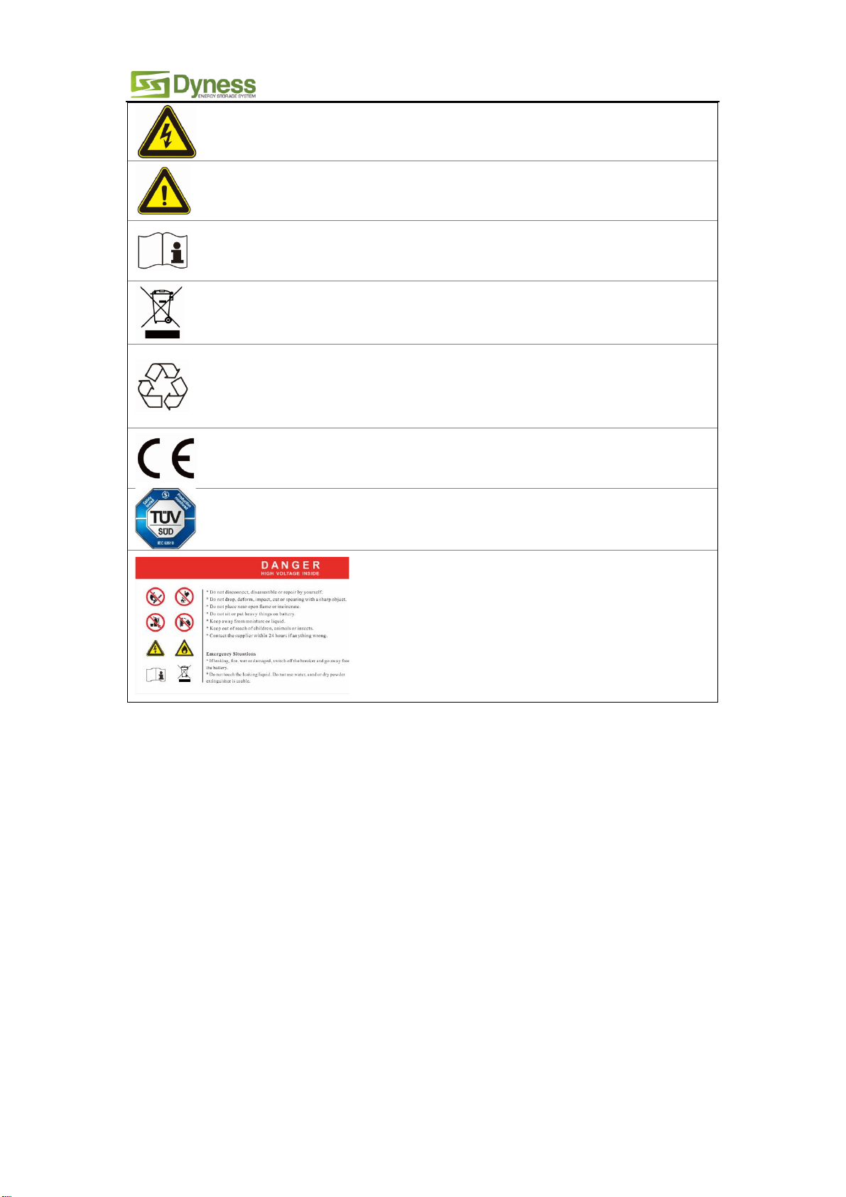
Safety Precautions
_____________________________________________________________ 2
Preface
________________________________________________________________________ 3
1 Introduction
_________________________________________________________________ 4
1.1 Brief Introduction ________________________________________________________________ 4
1.2 Product Properties _______________________________________________________________ 4
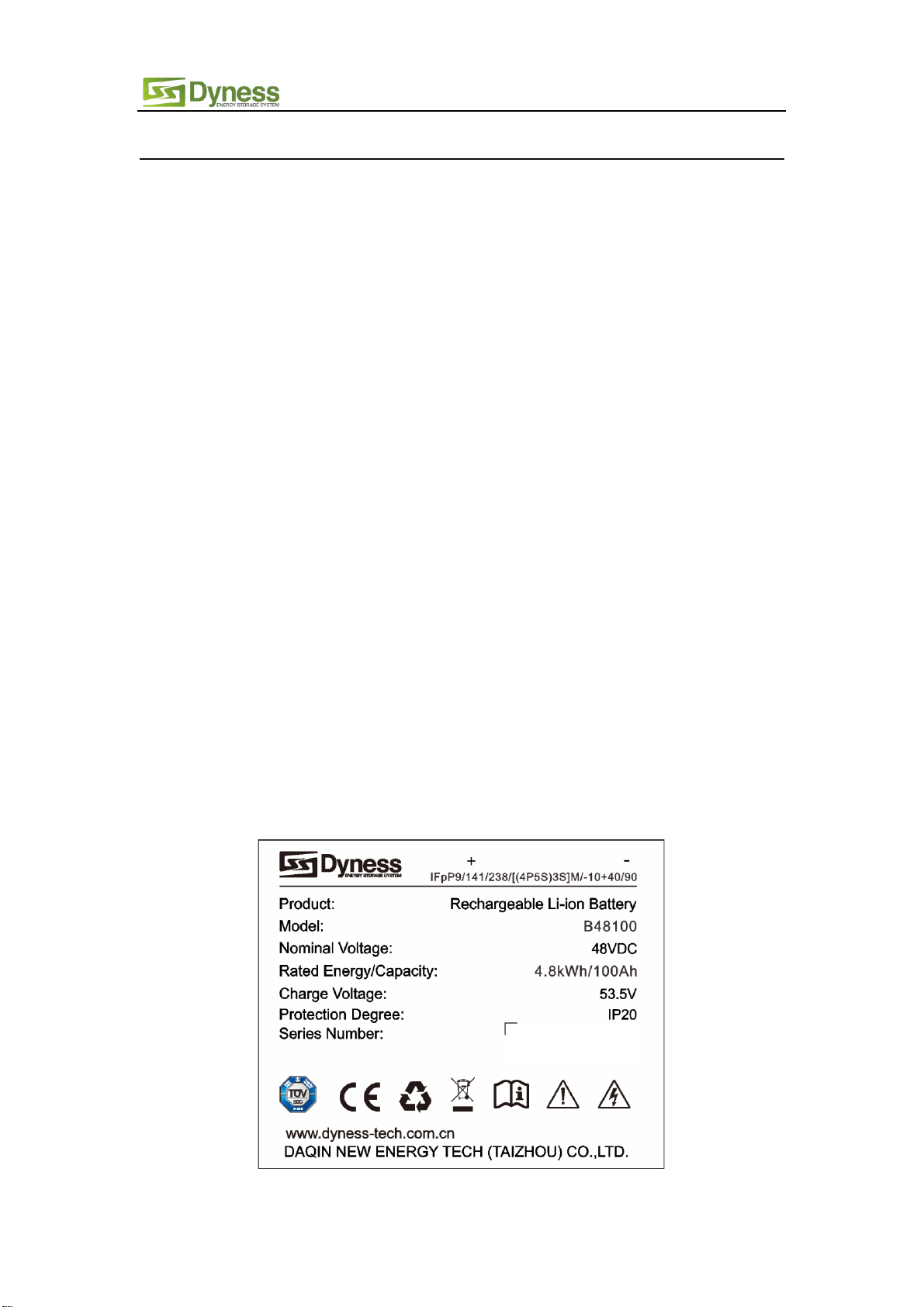
1.3 Product identity definition _______________________________________________________ 4
2 Product Specification
_________________________________________________________ 5
2.1 Size and Weight __________________________________________________________________ 5
2.2 Performance Parameter__________________________________________________________ 5
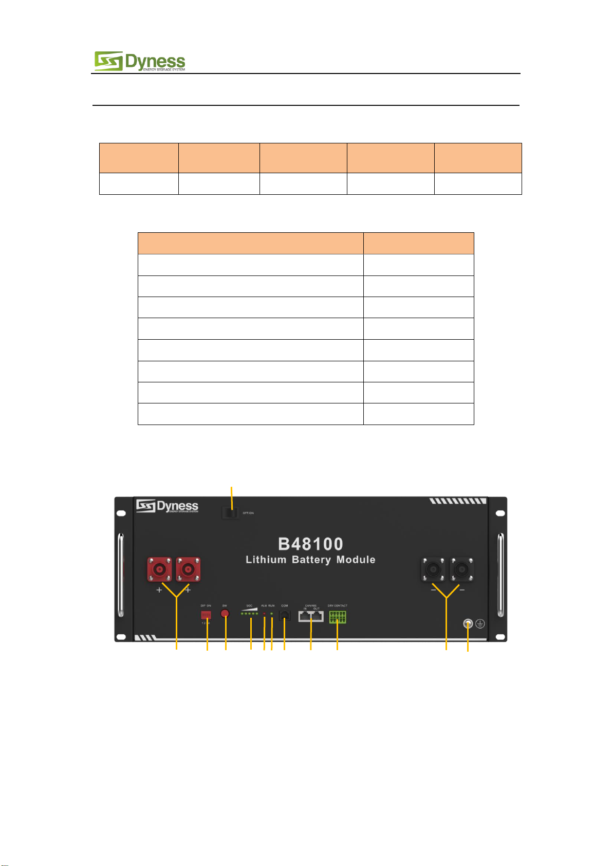
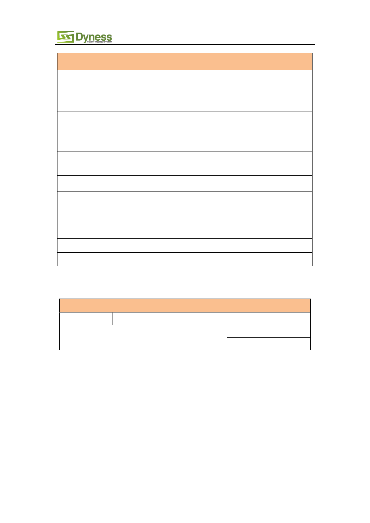
2.3 Interface Definition ______________________________________________________________ 5
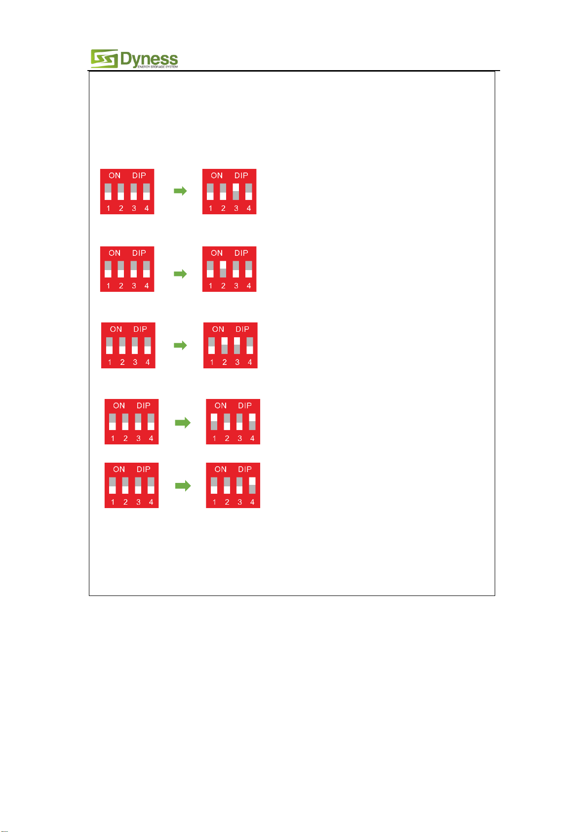
2.3.1 DIP switch definition and description ___________________________________________________ 6
2.4Battery Management System(BMS)_______________________________________________ 9
2.4.1 Voltage Protection _____________________________________________________________________ 9
2.4.2 Current Protection _____________________________________________________________________ 9
2.4.3 Temperature Protection ______________________________________________________________10
2.4.4 Other Protection______________________________________________________________________10
3 Installation and Configuration
_______________________________________________ 11
3.1 Preparation for installation_____________________________________________________ 11
3.1.1 Environmental requirements__________________________________________________________11
3.1.2 Tools and data ________________________________________________________________________11
3.1.3 Technical preparation _________________________________________________________________12
3.1.4 Unpacking inspection _________________________________________________________________12
3.1.5 Engineering coordination _____________________________________________________________14
3.2 Equipment installation _________________________________________________________ 14
3.2.1 Installation preparation________________________________________________________________14
3.2.2 Mechanical installation ________________________________________________________________15
3.2.3 Electrical installation __________________________________________________________________15
3.2.4 Battery parameter settings on the inverter ____________________________________________17
3.2.5 Register on the website after installation ______________________________________________17
4 Use, maintenance and troubleshooting
______________________________________ 18
4.1 Battery system usage and operation instructions _______________________________ 18
4.2Alarm description and processing_______________________________________________ 18
4.3Analysis and treatment of common faults ______________________________________ 19