2/27
E-VLT User Manual / Ref. MAN_E-VLT_EN_V1.0
Introduction................................................................................................. 3
Safety Guidelines......................................................................................... 4
Maintenance and Storage .................................................................................. 4
Before Use........................................................................................................... 4
Usage Precautions .............................................................................................. 5
Disassembly/Damage/Removal ......................................................................... 5
Cleaning the Product.......................................................................................... 5
Getting Started ........................................................................................... 6
Safety Reminders................................................................................................ 6
Appearance and Dimensions ............................................................................. 6
Presentation ........................................................................................................ 7
Couplers .............................................................................................................. 8
Accessories.......................................................................................................... 8
Initial Setup.................................................................................................. 9
Installation........................................................................................................... 9
Power Cable Connection and Power On........................................................... 9
Preamble............................................................................................................ 10
Keys.....................................................................................................................11
Power up.............................................................................................................11
Optimus ..................................................................................................... 12
Optimus installation.......................................................................................... 12
Using Optimus................................................................................................... 14
Update............................................................................................................... 16
Preparing a program......................................................................................... 18
Preparing a battery group program ................................................................ 18
Selecting a battery to test................................................................................ 19
Starting and stopping cycle ............................................................................. 20
Settings...................................................................................................... 21
Program parameters......................................................................................... 21
Wi-Fi Connection .............................................................................................. 24
Support Information ......................................................................................... 25
Warranty.................................................................................................... 26
Table of Contents
E-XTEQ E-VLT USER MANUAL
REVISION OF THE MANUAL
Due to software updates, your experience of the software interface (including but not limited to software features, user interfaces, and
interaction experiences) may differ from the interface presented in this manual. The software interface is subject to change.
Table of Content
Introduction
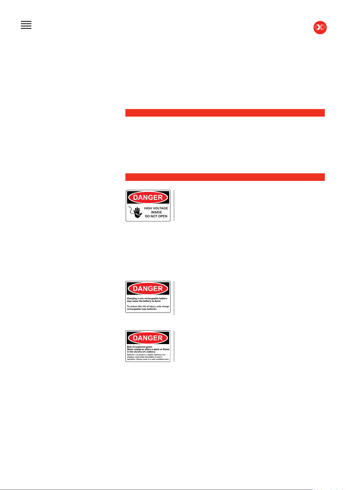
Safety Guidelines
Maintenance and Storage
Before Use
Usage Precautions
Disassembly/Damage/Removal
Cleaning the Product
Getting Started
Safety Reminders
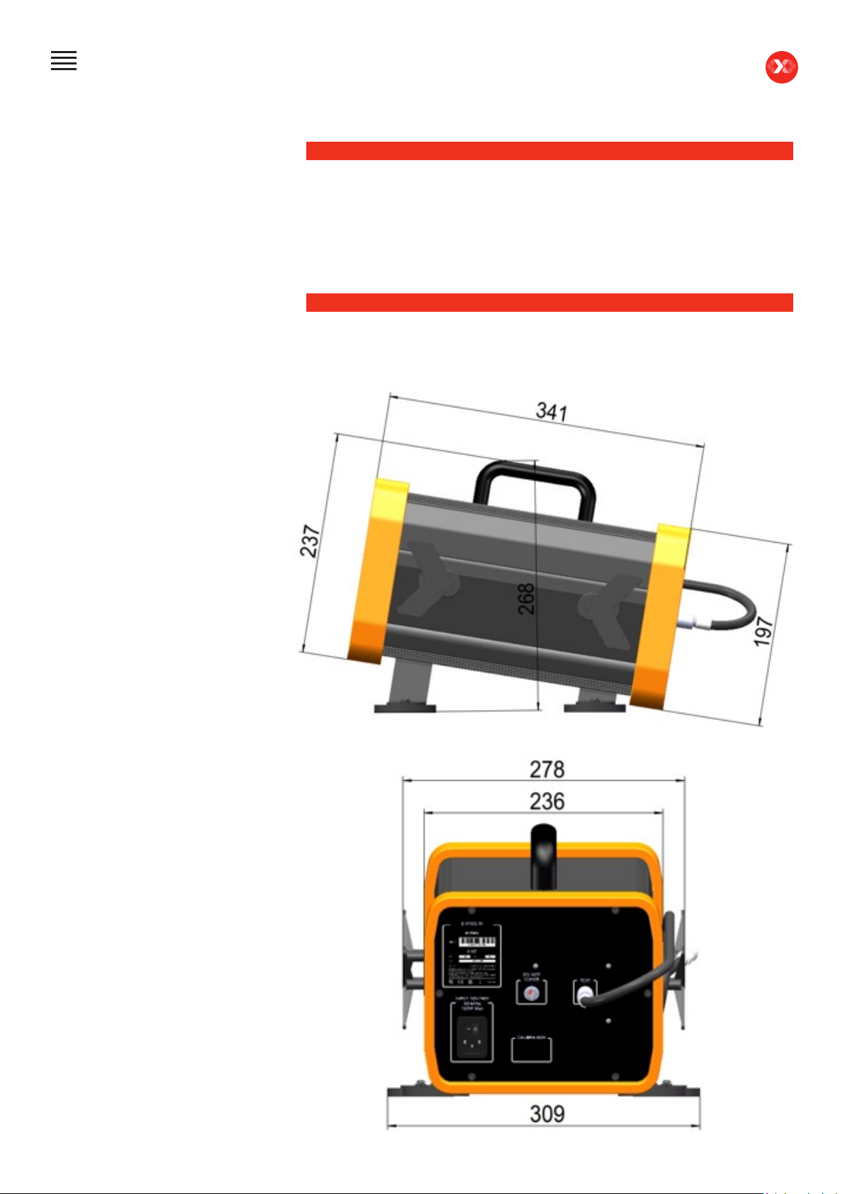
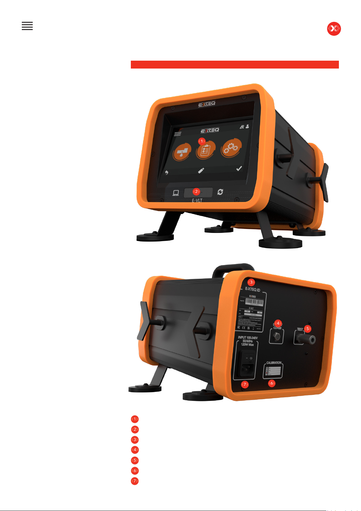
Appearance and Dimensions
Presentation
Couplers
Accessories
Digital Links
Initial Setup
Installation
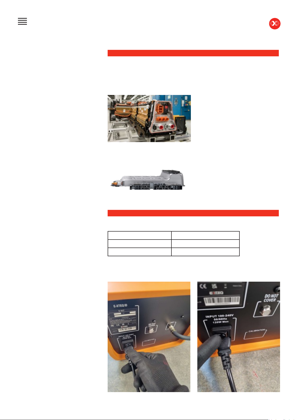
Power Cable Connection and Power On
Preamble
Keys
Power up
Optimus
Optimus installation
Using Optimus
Update
Preparing a program
Preparing a battery group program
Selecting a battery to test
Starting and stopping cycle
Settings
Program parameters
Wi-Fi Connection
Support Information
Warranty
EDITION / REVISION REFERENCE DATE UPDATES PARTS
First edition MAN_EVLT_EXTEQ_EN_V1.0 April 2023 -