6
EASTMAN
Form CR-50-0433
OPERATION
CAUTION
Before connecting power supply, make sure voltage
rating is same as stamped on terminal block. Damage
to control unit may result if incorrect power supply is
used.
When power supply is properly connected, air line is con-
nected and harnesses are attached, the Blue Jay is ready
for operation.
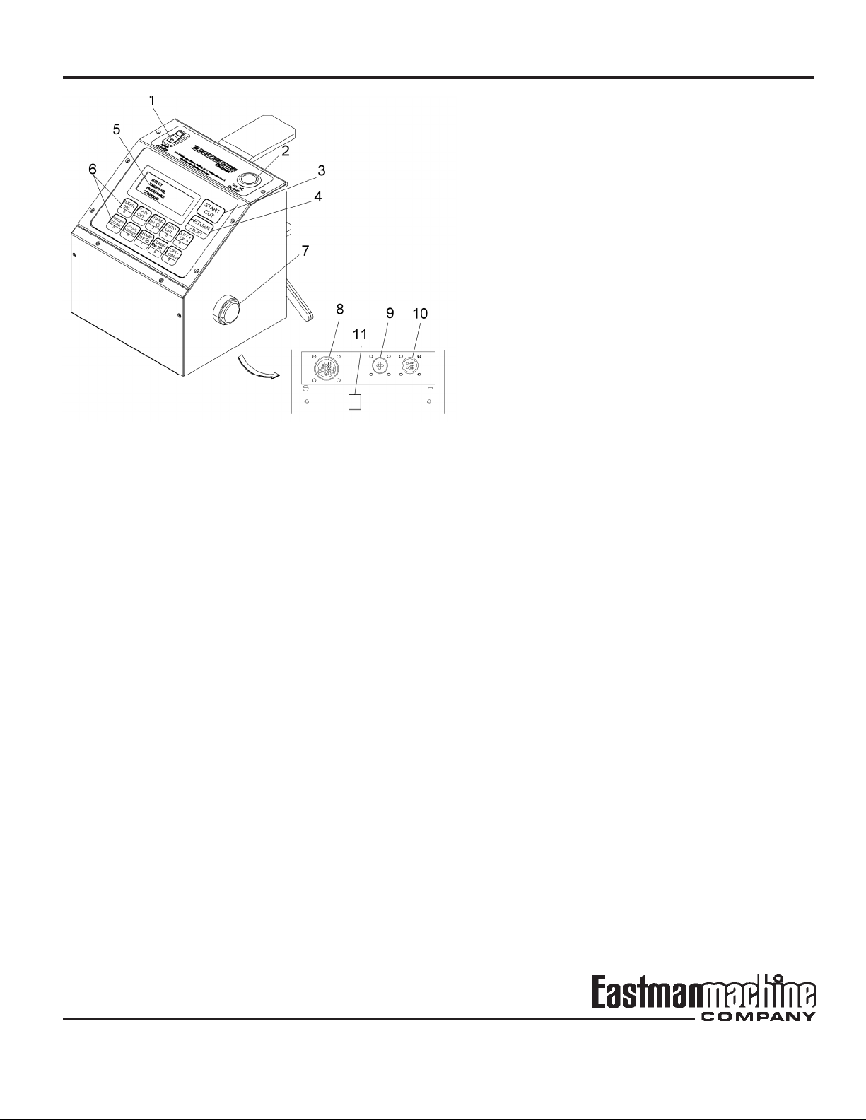
Activate main power by pressing MAIN POWER switch to
ON position. The LCD display will go on and the display will
show "000". The control box can now be programmed.
To program the number of plies desired, press the Preset
Count key. Use the Number keys to set the desired number
of plies.
NOTE: If "000" is programmed, the Blue Jay will count the
number of plies without interruption.
After the ply count is programmed, the Auto Lift should
display On. Switch the cutter to the ON position and the Blue
Jay is now ready for operation.
Press the Clamp key to open the Power Clamp.
Thread the material between the clamp and the chute.
Using an operator on each side of the table, pull the material
to the desired length. Smooth and align the edges of the
material. Press the START key to cut and clamp the first ply
of material. Continue this cycle until desired number of plies
have been spread and cut.
To remove the material, press the Lift Up key to raise the
track. Remove the material. Press Lift Down key to lower
the track. The track will lower and the blue Jay in ready to
continue.
CAUTION
The lift is designed to raise track with force. To Prevent
injury, Personnel should stand well clear of track when
in operation. All operators should be trained in the
operation of the machine prior to use.
IMPORTANT: To stop the Blue Jay at any point during
operation, press the power ON-OFF switch
to OFF position or hit the Emergency Stop
button on the main lift module.
Simplified Operating Instructions
1) Activate Main Power.
2) Program Ply Counter.
3) Thread material and Spread to length.
4) Press Remote Start Button to begin cut.
Operating Adjustments
This machine is adjusted and tuned at the factory for optimal
performance. No adjustments other than normal setup are
necessary. However, if after continued use the perfor-
mance level becomes unacceptable, the following proce-
dures should be carried out before repairs are considered.
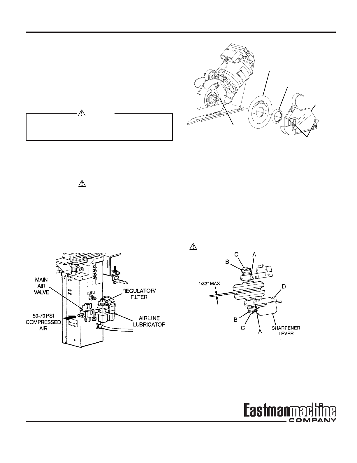
Power Clamp Pressure
The power clamp pressure may vary slightly depending on
the material. To adjust Clamping Pressure, remove the
covers for the main drive module. Locate the speed control
fittings on the clamp valve. Turn knobs for proper adjust-
ment. Proper adjustment will firmly clamp the material to the
chute without excess force then release the fabric gently.
Track Clamping Pressure
The track clamping pressure may vary slightly depending
on the material or method of spreading. To adjust Clamping
Pressure, locate to Switch Actuating Lever under the Track
and Chute assembly. Loosen the setscrew and adjust
accordingly. Do Not Adjust Track Feelers. Proper adjust-
ment will clamp the material to the table without excess
force. Replace covers.
Main Drive Belt Adjustment
The drive belt tension is set during installation and may need
to be adjusted from time to time. To Set tension, remove
both main drive side covers and lower the track and chute
assembly. Release both hand clamps. Loosen the tension
bars and slide bars up to increase tension. Do Not Over
tighten or damage to drive shaft may occur. Replace side
covers.
Note: The drive belts raise and lower track evenly. If track
misalignment occurs loosen the main drive pulleys. Align
the track and secure the pulleys.
Cutting Speed
The cutting speed will vary slightly depending on material to
be cut. To adjust cutting speed, locate to Knife Travel knob
on the main lift module. Turn the knob clockwise to increase
the speed of the cutter moving down the track and counter-
clockwise to decrease speed. If cutter tends to lag when
cutting, less speed is required.