EASTMAN
2
This machine is equipped with a sharp knife.
Keep hands away from the knife area at all
times. Use control levers and handles only
when operating or handling machine. When
machine is not in operation the KNIFE
GUARD/PRESSURE FOOT should be kept
lowered (by depressing lever B) to the base
plate at all times, except when changing
the knife or performing similar maintenance.
When making a cut the KNIFE GUARD/
PRESSURE FOOT should be raised by
handle G only enough to clear the material
being cut. When this equipment is not be-
ing utilized, the power supply should be
disconnected from the machine.
WARNING:
The purchaser must instruct all operators on the proper use of
the equipment. All standard industrial safety measures and
equipment should be provided to protect the operator. Opera-
tors must be cautioned that improper use of this equipment can
cause bodily injury. If you do not have qualied operators to
instruct new persons, contact your Eastman sales representative
or write to Eastman Machine factory direct.
Before starting the motor, be sure that electric supply voltage
and current are the same as stamped on the nameplate.
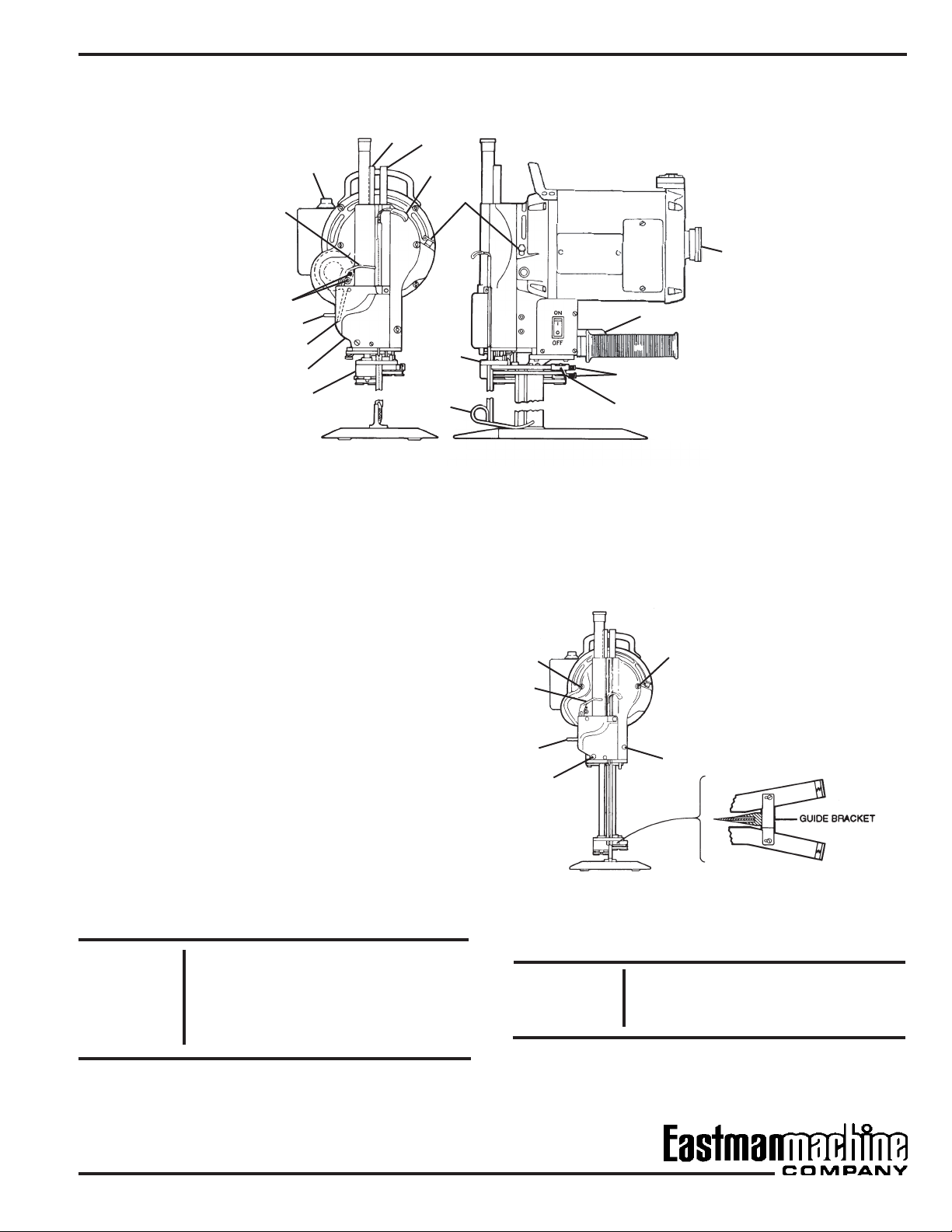
Fill oil cup F (see illustration page 3). Make sure the sharpener is
in locked position. Push in turning knob A and turn the machine
over a few revolutions by hand to see if the knife moves easily.
If the knife does not move easily, sharpener is probably in an
unlocked position. Use bell crank release lever N to return
sharpener to locked position.
Proceed as follows: Check to see that motor switch is in off
position. Connect attachment plug to terminal block on machine.
With left hand straddle front of sharpener with ngers and
thumb. Press in release lever N to dis-engage sharpener
mechanism from motor. With right hand turn on motor switch,
allow motor to gather full speed and then release lever N. This
will automatically return sharpener to locked position. Knife
must be in machine.
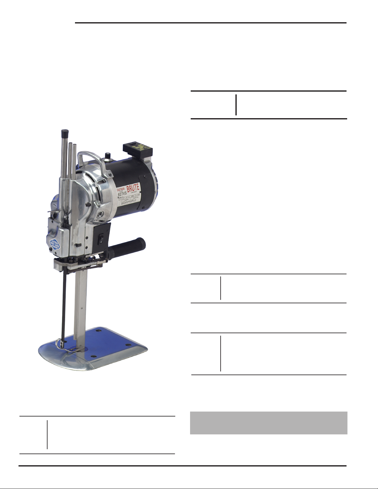
The variable speed straight knife ranges in speeds of 1,200 to
4,000 RPM depending on the control setting. The setting, de-
pending on operator preference, can be decreased by turning
the speed control knob "1" counter-clockwise to a lower number
(0=1,200 rpm) or increase by turning clockwise to a higher number
(10=4,000 rpm).
For the rst week or two, or after the machine has been idle for
any length of time, the motor should be turned on and off a few
times before running continuously. This permits the oil to warm
up and ow easily into the closely t moving parts. IN COLD
WEATHER, PLEASE KEEP MACHINE IN WARM PLACE.
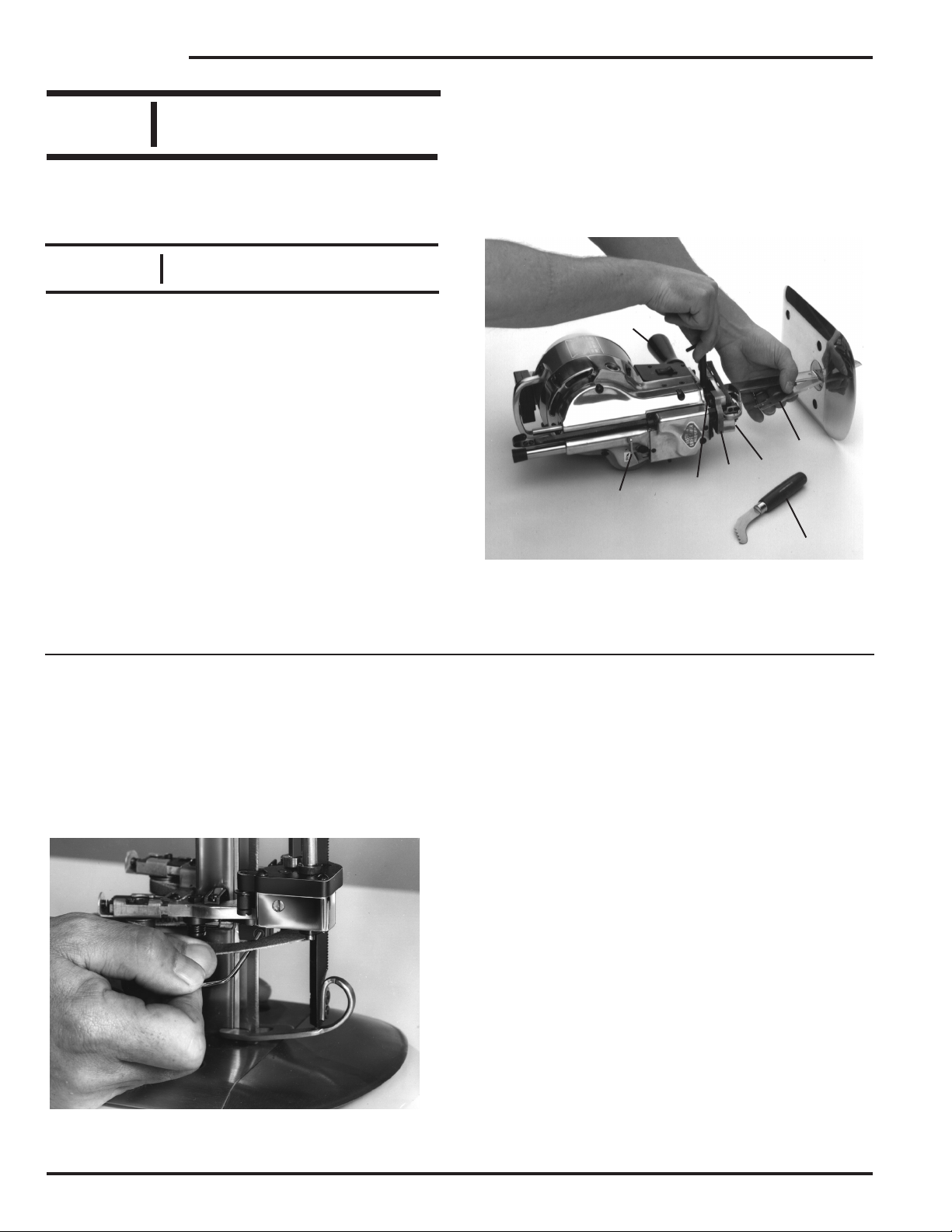
Before performing any of the following
procedures, make sure that the attach-
ment plug has been disconnected from
power source.
Operation,
Lubrication
And Care
Before operating machine, read
these instructions carefully.
Familiarize yourself with all
functions and adjustments of this
equipment.
Do not operate sharpener without
knife in machine or the sharpener
will be damaged. Do not shut off
motor while sharpener is in motion.
IMPORTANT:
Depress bell crank 584C3-16
release lever to return sharpener to
locked position before starting.
WARNING:
WARNING:
Operating
Handle
Knife Guard-
Pressure Foot
Carrying Handle