EASTMAN MPC 5000 User manual

779 Washington St., Buffalo, N.Y. 14203-1396 U.S.A. • (716)856-2200 • Fax (716)856-1140 or (716)856-2068
ManufacturersofEastmanClothCuttingandClothSpreadingMachines
Website: www.EastmanCuts.com
FormE-551
Technical Support:
1-800-872-5595
WARNING
Thismachineisequippedwithaverysharp
knife. Keep hands, arms, and hair away from
the knife area at all times.
Misuse of this machine or failure to follow all
safety instructions on this machine and in the
instruction manual may result in serious
personalinjuries.
THE EASTMAN®
Multi-Ply
Automatic Cutting System
Model: MPC 5000
Service Manual

2FormE-551
Congratulations
Congratulations in selecting anMulti-Ply Cutter. With over 100 years of experience in the cutting room, Eastman is a
world leader in cutting equipment. Every Eastman employee takes pride in each machine we build and back it with
unprecedentedsupport. OurTechnicalServicedepartmentis made up of a dedicated staffofprofessionals with years
of experience installing, troubleshooting and servicing the Multi-Ply Cutter. Each technician is familiar with all
aspectsof the machine including mechanical, electricaland software.
EastmanMachine Company provides technical support andon-siteserviceas required. We offer several affordable
Extended Warranty plans that allow you to continue the superior technical support well after the machine is past our
standardwarranty. If you require on-site technical support or would like to schedule a preventive maintenance visit or
needadditionaltraining,pleasecallourheadquartersinBuffalo,NYto arrange for a technician.
Technical Support EastmanMachine Company
779 Washington Street
Buffalo, NY 14203
Phone:716-856-2200
Fax: 716-856-2068
Limited Warranty. Eastman warrants to the buyer that the equipment shall be free from defects in materials or
workmanship for a period of 180 days commencing on the date of invoice. Any goods or parts claimed by the buyer
to be defective must be returned to Eastman, freight charges prepaid, within the 180 day warranty period. If
Eastman determines that the goods or parts are defective in materials or workmanship, Eastman’s sole obligation
under this warranty shall be, at Eastman’s sole option, to repair or replace the defective goods or parts or to provide
the buyer credit equal to the portion of the purchase price allocable to the defective goods or parts. This warranty
should not apply if defects are caused by product misuse or neglect, if the machine has been altered or modified by
the buyer or if other than genuine Eastman parts are used in the machine. THIS WARRANTY ISAPPLICABLETO
THISPURCHASEONLY. SELLERDISCLAIMSALLOTHER WARRANTIES,EXPRESSED OR IMPLIED,
INCLUDING,BUTNOTLIMITEDTO,THEIMPLIED WARRANTIESOFMERCHANTABILITYANDFITNESS FORA
PARTICULARPURPOSE.
Limitation of Liability. Eastman’s liability to the buyer, and the buyer’s remedies from Eastman whether in contract,
negligence,under anywarrantyor otherwise,shallbe limited totheremedies providedinthe foregoingLimitedWarranty.
In no event shall Eastman have any responsibility or liability to the buyer for (a) any special, indirect, incidental, or
consequentialdamages, including, but not limited to, loss of use,revenue, or profit even if Eastman has beenadvised
of the possibility of such damages, or (b) any claim against the buyer by any third party. The price stated for the
product sold is a consideration for limiting Eastman’s liability.
IMPORTANT
The purchaser must instruct all operators on the proper use of this equipment. All standard industrial safety mea-
suresandequipmentshouldbeprovidedtoprotecttheoperator. Operators must be cautioned that improper or
careless use of this equipment may cause personal injury. If you do not have qualified operators to instruct new
persons,contactyourEASTMANsales representative or EASTMAN factory direct.
Electrical connections and servicing to this equipment should be made by a qualified electrician who is familiar with
applicablecodesandregulations. Disconnectthisequipmentfrom electrical power source before proceeding with
anydisassemblyforadjustmentor repair.
Your Eastman Multi-Ply Cutter is designed to operate at a high rate speed. All personnel should be instructed to
wear safety glasses and stand well clear of the Multi-Ply Cutter wheninoperation.

3
FormE-551
Table of Contents
InstructionforAligning,CleaningandReplacing Consumable Parts.................................................4
Replacementof Knife ......................................................................................................... 4
Replacementof Sharpening Wheels................................................................................... 7
Replacementof Drill Rod .................................................................................................... 9
Replacementof Guide Bushing ........................................................................................ 11
ReplacementofVacuumFilter.......................................................................................... 13
Replacement of Bristle Block ........................................................................................... 15
Replacementof Polythene Rolls....................................................................................... 16
DisassemblyandAssembly Instructions for Partsrequiring Service .............................................. 17
ReplacementofX Motor Belts .......................................................................................... 17
Replacement of Y Motor Belt............................................................................................ 22
Replacementof Theta Motor Belt ..................................................................................... 27
Replacingthe X-axis LinearBearings ............................................................................... 28
ReplacingtheY-axisTopLinearBearings......................................................................... 31
ReplacingtheY-axis Front Linear Bearings ...................................................................... 34
ReplacingofTake-offConveyorDriveBelt ......................................................................... 38
ReplacingofTake-offConveyor Belt .................................................................................. 41
Replacingthe XMP ControllerCardand LoadingConfigurationFiles ................................. 45
AdjustmentProceduresand SpecificationsforpartsrequiringService ...........................................46
CheckingandAdjusting Gantry Backlash......................................................................... 46
Checking andAdjusting Y-car Backlash ........................................................................... 49
Checking andAdjusting Stop Discs .................................................................................. 52
ScheduledMaintenance Procedure ...............................................................................................54
LubricationChart .............................................................................................................. 56
Yearly Maintenance Checklist for Multi-Ply....................................................................... 57
Trouble ShootingGuidesandAides...............................................................................................66
UITError Messages ......................................................................................................... 66
AdditionalTrouble Shooting .............................................................................................. 67
RF/EMIInterference ......................................................................................................... 73
Electrical Schematics & Pneumatic Diagrams ..............................................................................73

4FormE-551
Instruction for Aligning, Cleaning and Replacing Consumable
Parts
Replacement of Knife
Removing the Knife
1. Removethe thumb screw found on the front portion of tool head cover which secures the cover to the tool
head.
2. Carefully swing the tool head cover and move it upwards to ensure it is in upper position.
3. Ensure that the reciprocating housing is in upper position.
4. Using allen wrench release the two socket head cap screws from the top of the blade link.
5. Move the blade link upwards along with the coupler assembly and the knife.
6. Afterthe blade link, coupler assembly and knife are completely removed from the reciprocating housing,
holding the coupler, loosen the clamping bolt found on the top surface of coupler using allen wrench.
NOTE: The screw will first become slightly lose and easy to turn, then it will become tight. Continue turning after it
tightens. It will then become lose again.After it loosens for the second time, the knife can easily be
removed.

5
FormE-551
7. Pulltheknife away from the coupler being careful to keep hands away from the sharp knife edge.
8. Ensure that the removed knife is placed in a safe area because it contains sharp edges that pose
hazards.

6FormE-551
Replacing the Knife
1. Insert the new knife into the coupler.
2. Ensure that the sharp edge of knife should face the direction of the spring plunger.
3. Push the knife into the coupler until it stops. Make certain the knife is pushed past the ball plunger
detent.
4. Tightenthe clamping bolt.
5. Lightly grease the outside diameter of the coupling assembly using Eastman No. 67-26324.
6. Insert the knife along with the coupler and blade link from the top into the reciprocating housing. The
below picture shows the knife and coupler assembly installed in the upper, middle and lower knife guide
assemblies. While holding the blade link gradually insert the knife along with the coupler into the recipro
cating housing guide tube. Ensure that the back edge of knife is facing the lower knife back roller. (The
lower knife guide back roller can be seen by pressing down the spring loaded presser foot assembly).
Thetip of the knife should pass through the rectangular opening in the throatplate found on upper knife
guide. Ensure that the knife is kept in the vertical position so that the knife tip passes between the guide
rollersfound on the upper knife guide. Continuelowering the knife and coupler until thecoupler engages
the guide tube. Now at this point the knife and coupler are fully guided as it is lowered until the upper
holes in the blade link match with the holes in lower arm.

7
FormE-551
7. After aligning the upper portion of blade link return the two socket head cap screws and secure it using
allen key.
Replacement of Sharpening Wheels
Removing the Sharpening Wheels
1. Remove the thumb screw found on the font portion of tool head cover which secures the cover to the tool
head.
2. Carefully swing the tool head cover and move it upwards to ensure it is in upper position.
3. Ensure that the reciprocating housing is in upper position.
4. Using allen wrench release the two socket head cap screws from the top of the blade link.
5. Move the blade link upwards along with the coupler assembly and the knife.
6. Afterthe blade link, coupler assembly and knife are completely removed from the reciprocating housing,
remove the rotating tool head assembly as per the instructions below.
7. Disconnect all wires connected to intellicut.
8. Hold the bottom of the rotating tool head in one hand and then release the screw which holds the rotating
tool head housing to the shaft.
9. Nowrotating toolheaddropsdown.
10. Using allenkeyremove the screws which hold the sharpening wheelsand remove the worn-out
sharpeningwheels

8FormE-551
Replacing the Sharpening Wheels
1. Using a clean dry cloth saturated with alcohol clean the mounting surfaces of the sharpening housing.
2. Apply a few drops of “loctite 222 MS” on the end of screws which hold the sharpening wheels.
3. Installthe newsharpeningwheels.
4. Return the screws to hold the grinding wheels.
5. Return the rotating tool head and ensure when you put back the tool head on the shaft the pin on the tool
head should be aligned to the key way on the shaft (ref image).
6. Raise the tool head after alignment with keyway to upper position until it stops.
7. Tighten the screw which holds the rotating tool head housing to the shaft.

9
FormE-551
Replacement of Drill Rod
Removing the Drill Rod
1. Remove the thumb screw found on the font portion of tool head cover which secures the cover to the tool
head.
2. Carefully swing the tool head cover and move it upwards to ensure it is in upper position.
3. Using the supplied chuck key turn counter clockwise to loosen the drill chuck.
4. After the drill chuck is loosened the drill rod will drop down.
5. Manually lift the drill pressure foot upwards until the drill rod is removable.

10 FormE-551
Replacing the Drill Rod
6. Lift the drill pressure foot high enough to install the new drill rod.
7. Insert the new drill rod through the drill bushing into the drill chuck.
8. Hold the drill rod in one hand and tighten the drill chuck using the chuck key as required.

11
FormE-551
Replacement of Guide Bushing
Removing the Guide Bushing
1. Remove the thumb screw found on the font portion of tool head cover which secures the cover to the tool
head.
2. Carefully swing the tool head cover and move it upwards to ensure it is in upper position.
3. Using the supplied chuck key turn counter clockwise to loosen the drill chuck.
4. After the drill chuck is loosened the drill rod will drop down.
5. Manually lift the drill pressure foot upwards until the drill rod is removable.
6. Using allen wrench loosen the set screw found on the drill pressure foot.
7. Usingfingers push the drill bush from the bottom of the pressure foot and remove the worn-out guide
bushing.

12 FormE-551
Replacing the Guide Bushing
1. Install the new guide bushing into the hole of the drill pressure foot.
2. Since the guide bushing has (4) different size holes align the correct size hole which matches the drill
rod.
3. Rotate the guide bushing until the drill rod is aligned with the hole of the drill chuck.
4. Tighten the set screw on the drill pressure foot and ensure that the drill rod is aligned with the hole in the
guidebushing.
5. Tighten the drill chuck after the drill rod is aligned and inserted correctly.

13
FormE-551
Replacement of Vacuum Filter
Removing the Vacuum Filter
1. Usingflat head screw driver remove the screws whichhold the filter box cover plate.
2. Removethe wing nut which holds the filter coveron filter housing.
3. Removethefiltercoverfrommountingstud.

14 FormE-551
4. Slidefilter cartridge from the filter housing.
5. Shakethe cartridgeoveranopen garbage can.
6. Using clean dry compressed air blow out filter until clean.
7. Replacewith new filter if required based oninspection.
Replacing the Vacuum Filter
1. Installa new filter.
2. Usingvacuum cleanerremovealldebris found inside the filter chamber.
3. Returnthe cleanedfilter cartridge and cover the filter housing.
4. Inspectthe seal found on the filter boxcover for any damage andrepair as required.
5. Carefully return the filter box cover plate to the machine and secure it using the mounting screws.
6. Cover the cutting surface with polythene plastic and start the vacuum pump. Check the vacuum level in
the software and inspect for any audible leaks. Repair any leaks found.

15
FormE-551
Replacement of Bristle Block
Removing the Bristle Block
1. Advancethe conveyortoexposedamaged bristle.
2. ApplyE-stop toprevent the conveyor and gantry movement for safely.
3. Using a pair of pliers grab the bristle of the bristle block to be removed and pull from its aluminum slot.
Replacing the Bristle Block
1. Install the new bristle block by ensuring that the tab alignment is proper according to the slat
arrangementonthealuminum slat. (refer image).
2. Apply pressure on the surface of bristle block so that the mounting tabs snap in the slat found with in the
aluminum slat.
3. ReleasetheE-stopallowingconveyorandgantrymovementand advance conveyor and inspect the
remainingbristleblock and replace damaged bristles as required by following theaboveprocedure.

16 FormE-551
Replacement of Polythene Rolls
Instructions
1. Twopersons are required one on eitherside of the machine.
2. Lift up the bar which holds the plastic overlay tube and set it on flat surface.
3. Pull out the bar from tube and insert into a new roll.
4. Replacethe barontower and thread under the elevation bar as required.

17
FormE-551
Disassembly and Assembly Instructions for Parts requiring
Service
Replacement of X Motor Belts
Removing the X Motor Belts
1. Power down the machine using proper shut down / lock out procedures.
2. Removethe (6) screws using hexagonal wrench found on the left and right side of covers from both the
operatorandnon-operatorsideofthegantry.
3. Removethe (6)screws using hexagonal wrench found on the control panel fromboth the operator and
non-operatorside of the gantry and place thecontrol panel upwards.

18 FormE-551
4. Remove the (4) screws found on either side of the electronics tray and swing the electronics tray
outwards.
5. Loosen the (4) screws of the motor and now the motor will drop down to loosen the tension on the belt.

19
FormE-551
6. Cut the (2) zip ties found on the shaft support plate.
7. Removethe (6) screws found on the shaft support plate.
8. Rotate the shaft support plate to convenient orientation to get access to the belt.

20 FormE-551
9. Loosen the belt guide and push it outwards so that so that it will help relieve the tension on belt.
10. Remove thewornout belt.
Replacing the X Motor Belts
1. Take a new belt.
2. Put it on the big pulley and roll it on the motor pulley a couple of times until it seats itself.
Table of contents
Other EASTMAN Cutter manuals

EASTMAN
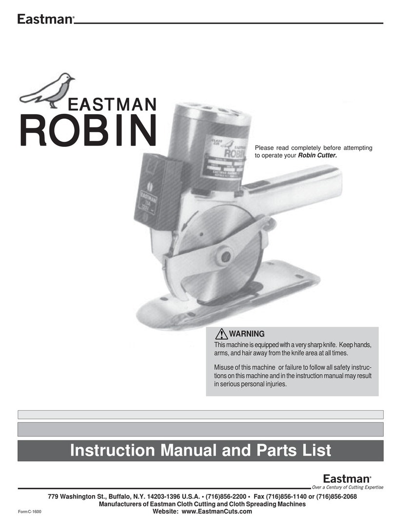
EASTMAN Robin User manual

EASTMAN
EASTMAN BLUE STREAK II User manual

EASTMAN
EASTMAN BLUE STREAK 2 629X User manual

EASTMAN
EASTMAN Falcon FAL-A User manual

EASTMAN
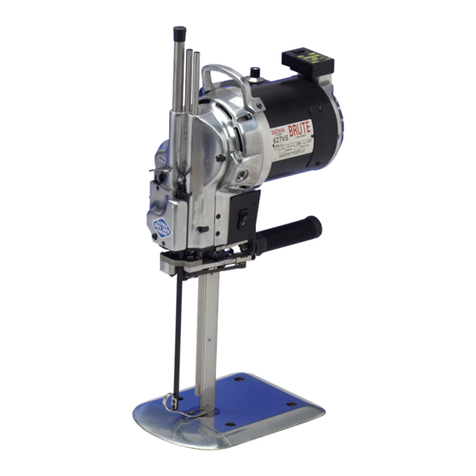
EASTMAN BRUTE 627VS User manual

EASTMAN
EASTMAN Raptor User manual

EASTMAN
EASTMAN RS2 User manual

EASTMAN
EASTMAN BLUE JAY-5H Setup guide

EASTMAN
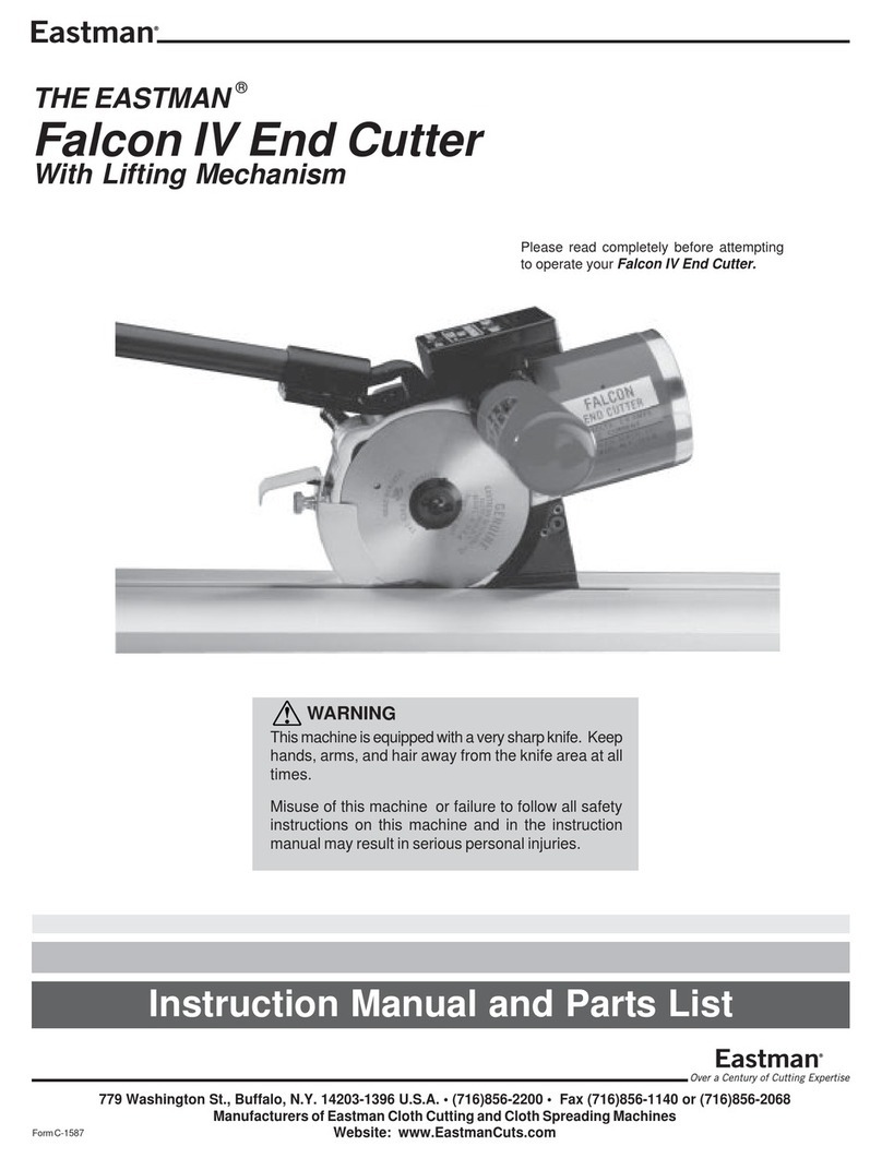
EASTMAN FALCON IV User manual

EASTMAN
EASTMAN Plastic Master 627PM Datasheet