manuals.online logo
Brands
  1. Home
  2. •
  3. Brands
  4. •
  5. Eaton
  6. •
  7. Control Unit
  8. •
  9. Eaton PXR-PCAM Manual

Eaton PXR-PCAM Manual

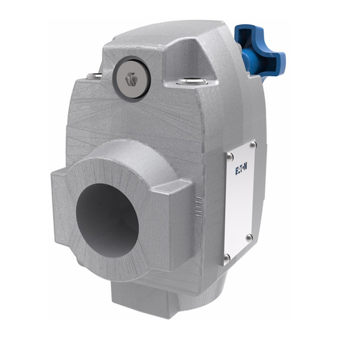
Cam expansion port
USB conf. port
CAM link status LED
Profibus Bus Fault LED
Slave Fault LED
Power OK status LED
18mm
(0.71”)
99mm
(3.9”)
35mm
DIN rail
mount
Mounting foot
24 VdcCAM/PXR link
PIN
Shell
1
2
3
4
5
6
7
8
9
Signal
Ground
NC
NC
Profibus B/D+
RTS
ISO COM
ISO 5V
NC
Profibus A/D-
NC
DIN Relay Mounting foot
Spring
clip
Profibus (DP) communication adapter module
Instruction Leaflet IL120009EN Effective March 2017 PXR-PCAM
Figure 1. Left = front view, right = side view
For use with PXR 20/25 electronic
trip units (ETUs). The PXR-PCAM
is designed to connect with a
circuit breaker’s CAM-PXR link
and expand the communication
capabilities into a slave Profibus
DP interface.
The module also provides limited
discrete I/O, circuit breaker control
capability, and data storage rele-
vant to the breaker. The module
is mounted local to the breaker to
keep the CAM-PXR link limited to
3m maximum
PXR –PCAM adapter
module specifications
• Weight: 0.36 lb.
• Housing width, height, length
(30 x 111 x 111mm)
• Housing NEMA 1, IP20
• Pollution degree 3, pcb is
conformally coated
• Operational/storage
temperature: -20 to +70ºC / -45
to + 85ºC
• Elevation: 0 - 2000m, humidity
5 - 95% noncondensing
• CE mark, RoHS compliant
• Safety: IEC/EN/UL61010-1, UL
file # E185559
• CNL evaluation to CAN/
C22.2 No 1010.1.92
• EMC EN61326 - IEC61000-4-X
level 3
• Emmisions: conducted and
radiated
• FCC part 15 & CISPR 11/22
class B
All terminal blocks are remov-
able, 5.08 mm (0.200”) and
support wires of 0.2-2.03 mm2
( 24-14 AWG). Ferrules recom-
mended for wire termination.
Power supply 24 Vdc +/- 20%,
6W maximum isolated CAM input
power with common/0V clamped
300V to GND. terminal identifica-
tion “TP.1-.3.” Connect TP1 near
CAM to assembly enclosure
ground as a functional ground.
DIN Three 24 Vdc +/-20% inputs
externally wetted, shared common
with ~5.0k ohm input impedance,
5mA draw. Terminal identification
TD.1-.4, shared with relay terminal.
DOUT − Two form A relays exter-
nally sourced, shared common hot
240 Vac/30 Vdc 2A CAT II max.
Terminal identification TD.5-.7. In
breaker mode (command format
0), relay 1 (TD5) is used to close
the breaker when Profibus control
is enabled, and relay 2 (TD6) is
used to open the breaker when
Profibus control is enabled. In
general mode (command format
1), relay 1 and relay 2 are used
for general purposes, and may be
independently opened and closed.
PB - DB9 Profibus DP interface,
shell grounded through TP1.
(see Figure 1)
Catalog
number Ethernet
protocol Style #
PXR-PCAM Profibus
DP slave
66D2355G01
WARNING
Be sure that all distribution
power is off when commission-
ing a PXR-PCAM with a circuit
breaker system.The module can
be powered temporarily via the
USB configuration port or
permanently with the 24 Vdc
power supply input.
IMPORTANT
Download the GSD file for the
PXR-PCAM on the Eaton website.
www.eaton.com/CAM
PXR-PCAM Fuse
Source
24 Vdc
source
Loads
Cassette
switches
Test
Rack out
5mA each
input
<30m
ISO
Rack in
+
+
-
-
DOUT
COM TD.7
TD.6
TD.5
TD.4
TD.3
TD.2
TD.1COM
RLY2
RLY1
IN1
IN2
IN3
DIN
Figure 2. Discrete input and output connections
2
PXR –PCAM adapter module specifications
PROFIBUS (DP) COMMUNICATION ADAPTER MODULE IL120009EN March 2017 www.eaton.com
DISCLAIMER OF
WARRANTIES AND
LIMITATION OF
LIABILITY
The information, recommenda-
tions, descriptions and safety
notations in this document are
based on Eaton Corporation’s
(“Eaton”) experience and
judgment and may not cover
all contingencies. If further
information is required, an
Eaton sales office should be
consulted. Sale of the product
shown in this literature is
subject to the terms and
conditions outlined in
appropriate Eaton selling
policies or other contractual
agreement between Eaton
and the purchaser.
THERE ARE NO
UNDERSTANDINGS,
AGREEMENTS, WARRANTIES,
EXPRESSED OR IMPLIED,
INCLUDING WARRANTIES
OF FITNESS FOR A
PARTICULAR PURPOSE OR
MERCHANTABILITY, OTHER
THAN THOSE SPECIFICALLY
SET OUT IN ANY EXISTING
CONTRACT BETWEEN
THE PARTIES. ANY SUCH
CONTRACT STATES THE
ENTIRE OBLIGATION OF
EATON. THE CONTENTS OF
THIS DOCUMENT SHALL
NOT BECOME PART OF OR
MODIFY ANY CONTRACT
BETWEEN THE PARTIES.
In no event will Eaton be
responsible to the purchaser
or user in contract, in tort
(including negligence), strict
liability or other-wise for any
special, indirect, incidental or
consequential damage or loss
whatsoever, including but not
limited to damage or loss of
use of equipment, plant or
power system, cost of capital,
loss of power, additional
expenses in the use of exist-
ing power facilities, or claims
against the purchaser or user
by its customers resulting from
the use of the information,
recommendations and descrip-
tions contained herein. The
information contained in this
manual is subject to change
without notice.
User interface
USB − Device interface full
speed micro B serial port. USB
host power will temporarily run
the module for configuration
purposes.
Status RED/GREEN LED
• Green on − power ok, 1Hz
blink − normal mode
• Red on − application alarm
active
CAM-PXR LINK RED/GREEN
LED
• Green on − active
communications with ETU
• Red on − communication
alarm
Profibus DP bicolor LEDs
BF (bus fault)
• Red − physical interface
issues (reflections)
• Green − ok
SF (slave fault)
• Red − initialization system
error
• Green − ok
Mounting − 35 mm DIN rail
blade style or alternative panel
mount with #8 or #10 screw.
(see figure 1)
CAM Expansion port − future
use only, do not connect.
CAM-PXR Link − RS422 inter-
face dedicated to interfacing
with circuit breaker electronic
trip units (ETU). Isolated
to CAM logic but common
clamped at 300 Vdc to GND
and electrically common with
24V return. Terminal identi-
fication l TC.1-.6). Distance
between ETU and module
limited to 3m maximum, use
shielded twisted pair cable.
Shield should be an aluminized
mylar with drain wire that
doubles as the RS422 return/
common. In ACB applications
the ETU’s Vaux power common
(AGND) doubles as the RS422
return. The PCAM makes this
connection internally and can
bus power to the ETU as a
third twisted pair via TC.1 &
TC.2.
NOTE
The ETU and CAM power
supply returns are electrically
common.
The PCAM supports the
Profibus DP profile for low
voltage switchgear devices
(LVSG): Circuit breaker device
classification. This classification
provides cyclic data exchange
structures for one command
(outputs from the Profibus
master to the PCAM slave)
format (Format 0) and four
monitoring (inputs from the
PCAM to the Profibus master)
formats (Format 0 – Format 3).
The PCAM also supports two
additional monitoring formats,
and one additional command
format. Monitoring formats
4 and 5 are similar to format
3, except the active energy
value is provided with a higher
resolution, and the on-board
digital inputs are provided. In
command format 0, the relays
are dedicated to opening and
closing the breaker. Command
format 1 is similar to command
format 0, except that the
on-board relays are general-
purpose and can be indepen-
dently opened and closed. The
General Station Description
file is EATON03F.GSD, which
will be used by the Profibus
master to retrieve the PCAM
characteristics. This can be
downloaded from www.eaton.
com/cam. Table 1 shows the
communication formats.
24 Vdc
Source
RX
RX TX
TX
TP
Shield drain
CMMC
MCCB ETU PXR-PCAM
CMM1+
CMM2-
CMM3+
CMM4-
<3m
TC
1
+
+
+
-
-
-
2
3
1
2
3
4
5
6
24 Vdc
Source
RX
RX TX
TX
TP
Shield drain
AGND
24V+
Vaux
ACB ETU PXR-PCAM
CMM1+
CMM2-
CMM3+
CMM4-
<3m
TC
1
+
+
+
+
-
-
-
-
2
3
1
2
3
4
5
6
Figure 3. MCCB CAM-PXR link connections
Figure 4. ACB CAM-PXR link connections
3
PXR –PCAM adapter module specifications
PROFIBUS (DP) COMMUNICATION ADAPTER MODULE IL120009EN March 2017 www.eaton.com
Table 1. Communication formats and profiles
Profile type Cyclic module Command
format Monitoring
format
1100
21 + 2 0 1
31 + 3 0 2
41 + 4 0 3
51 + 5 + 6 0 4
61 + 5 + 6 + 7 0 5
71 + 5 + 6 + 8 1 5
Command structure format 0 is described in Table 2.
Table 2. Cyclic data exchange command format 0
Byte Bits Description Implementation
0
1.0
Circuit breaker:
00 = no charge
01 = switch off
10 = switch on
11 = no change
Open breaker if remote enabled
Close breaker if remote enabled
2Clear last trip “Reset trip” issued to trip unit
7..3 Output 4..0 Not implemented
9.8
Test mode:
00 = no test
01 = w/o release
10 = w/ release
11 = w/ warning
No-trip phase current self-test at
3.0pu
Not implemented
Not implemented
1
10 Delete history Not implemented
11 1 = reset
min/max
“Reset all min/max values” issued
to trip unit
12 1 = reset temp.
min/max
Not implemented
13 Output 5 Not implemented
14 1 = reset maint.
info.
“Reset trip unit health buffer”
issued to trip unit
15 Clock synch Not implemented
Command structure format 1 is described in Table 3.
Table 3. Cyclic data exchange command format 1
Byte Bits Description Implementation
0
0
Relay 1 output:
0 = open relay 1
1 = close relay 1
1
Relay 2 output:
0 = open relay 2
1 = close relay 2
2Clear last trip “Reset trip” issued to trip unit
7..3 Output 4..0 Not implemented
9.8
Test mode:
00 = no test
01 = w/o release
10 = w/ release
11 = w/ warning
No-trip phase current self-test at
3.0pu
Not implemented
Not implemented
1
10 Delete history Not implemented
11 1 = reset
min/max
“Reset all min/max values” issued
to trip unit
Table 3. Cyclic data exchange command format 1
Byte Bits Description Implementation
12 1 = reset temp.
min/max
Not implemented
13 Output 5 Not implemented
14 1 = reset maint.
info.
“Reset trip unit health buffer”
issued to trip unit
15 Clock synch Not implemented
Monitoring structure formats 0-5 are described in Table 4 through
Table 9.
Table 4. Cyclic data exchange monitoring format 0
Byte Bits Definition Description
0
1.0
Position of breaker:
00 = disconnected
01 = operational
10 = test
11 = not present
No comm. with trip unit
Comm. w/trip unit
3.2
State of breaker:
00 = Init
01 = off
10 = on
11 = tripped
No comm. with trip unit
Open
Closed
Tripped
4Ready to switch on 1 = not implemented
5Undervoltage release 1 = tripped, cause = 12
6Spring loaded 1 = not implemented
7Overload warning 1 = pickup or alarm, cause = 61
1
8Setpoint activated 1 = alarm, cause = 11, 12, 15-18,
26, 27
9Warning 1 = alarm, cause = all except 61
10 Write protection
activated
1 = remote breaker control
disabled
11 Input 0 0 = not implemented
14..12
Release reason:
000 = no release
001 = L(ongtime)
010 = I(nstantaneous)
011 = S(hort)
100 = Earth fault
101 = Extended prot.
110 = Neutral
overcurrent
111 = no device info
Not tripped
Tripped, cause = 61 and not in
Tripped, cause = 3, 66, 76
Tripped, cause = 62
Tripped, cause = 84, 85
Tripped, cause = other
Tripped, cause = 80
No comm. with trip unit
15 Load rejection Alarm, cause = 26
Table 5. Cyclic data exchange monitoring format 1
Byte(s) Data type Description Resolution
0Uint8 State 0 (byte 0 of monitoring
format 0, Table 4)
1Uint8 State 1 (byte 0 of monitoring
format 0, Table 4)
3..2 Uint16 IL1 (phase A current) Amps
5..4 Uint16 IL2 (phase B current) Amps
7..6 Uint16 IL3 (phase C current) Amps
9..8 Uint16 ILmax (maximum value of IL1, IL2, IL3 Amps
4
PXR –PCAM adapter module specifications
PROFIBUS (DP) COMMUNICATION ADAPTER MODULE IL120009EN March 2017 www.eaton.com
Table 6. Cyclic data exchange monitoring format 2
Byte(s) Data type Description Resolution
0Uint8 State 0 (byte 0 of monitoring
format 0, Table 4)
1Uint8 State 1 (byte 0 of monitoring
format 0, Table 4)
3..2 Uint16 IL1 (phase A current) Amps
5..4 Uint16 IL2 (phase B current) Amps
7..6 Uint16 IL3 (phase C current) Amps
9..8 Uint16 ILmax (maximum value of IL1, IL2, IL3 Amps
11..10 Uint16 IN(neutral current) Amps
13..12 Uint16 VLL avg (average line-to-line voltage Volts
15..14 Int16 cos phi (avg apparent PF) 0.1%
17..16 Uint16 Energy MWh
Table 7. Cyclic data exchange monitoring format 3
Byte(s) Data type Description Resolution
0Uint8 State 0 (byte 0 of monitoring
format 0, Table 4)
1Uint8 State 1 (byte 0 of monitoring
format 0, Table 4)
3..2 Uint16 IL1 (phase A current) Amps
5..4 Uint16 IL2 (phase B current) Amps
7..6 Uint16 IL3 (phase C current) Amps
9..8 Uint16 ILmax (maximum value of IL1, IL2, IL3)Amps
11..10 Uint16 IN(neutral current) Amps
13..12 Uint16 VL1-L 2 (VAB)Volts
15..14 Uint16 VL2-L3 (VBC)Volts
17..16 Uint16 VL 3-L1 (VCA)Volts
19..18 Uint16 VL1-N (VAN)Volts
21..20 Uint16 VL2-N (VBN)Volts
23..22 Uint16 VL3-N (VCN)Volts
25..24 Int16 cos phi (avg apparent PF) 0.1%
27..26 Uint16 Energy MWh
29..28 Uint16 Stotal (total apparent PF) kVA
Table 8. Cyclic data exchange monitoring format 4
Byte(s) Data type Description Resolution
0Uint8 State 0 (byte 0 of monitoring
format 0, Table 4)
1Uint8 State 1 (byte 0 of monitoring
format 0, Table 4)
3..2 Uint16 IL1 (phase A current) Amps
5..4 Uint16 IL2 (phase B current) Amps
7..6 Uint16 IL3 (phase C current) Amps
9..8 Uint16 ILmax (maximum value of IL1, IL2, IL3 Amps
11..10 Uint16 IN(neutral current) Amps
13..12 Uint16 VL1-L 2 (VAB)Volts
15..14 Uint16 VL2-L3 (VBC)Volts
Table 8. Cyclic data exchange monitoring format 4
Byte(s) Data type Description Resolution
17..16 Uint16 VL 3-L1 (VCA)Volts
19..18 Uint16 VL1-N (VAN)Volts
21..20 Uint16 VL2-N (VBN)Volts
23..22 Uint16 VL3-N (VCN)Volts
25..24 Int16 cos phi (avg apparent PF) 0.1%
29..26 Uint 32 Energy kWh
31..30 Uint16 Stotal (total apparent PF) kVA
Table 9. Cyclic data exchange monitoring format 5
Byte(s) Data type Description Resolution
0Uint8 State 0 (byte 0 of monitoring
format 0, Table 4)
1Uint8 State 1 (byte 0 of monitoring
format 0, Table 4)
3..2 Uint16 IL1 (phase A current) Amps
5..4 Uint16 IL2 (phase B current) Amps
Cyclic data exchange monitoring format 4
Byte(s) Data type Description Resolution
7..6 Uint16 IL3 (phase C current) Amps
9..8 Uint16 ILmax (maximum value of IL1, IL2, IL3)Amps
11..10 Uint16 IN(neutral current) Amps
13..12 Uint16 VL1-L 2 (VAB)Volts
15..14 Uint16 VL2-L3 (VBC)Volts
17..16 Uint16 VL 3-L1 (VCA)Volts
19..18 Uint16 VL1-N (VAN)Volts
21..20 Uint16 VL2-N (VBN)Volts
23..22 Uint16 VL3-N (VCN)Volts
25..24 Int16 cos phi (avg apparent PF) 0.1%
29..26 Uint 32 Energy kWh
31..30 Uint16 Stotal (total apparent PF) kVA
33..32 Uint16
Digital inputs
bit 0 = DIN0
bit 1 = DIN1
bit 2 = DIN2
bit 3..15 = 0 (not used)
Eaton
1000 Eaton Boulevard
Cleveland, OH 44122
United States
Eaton.com
© 2017 Eaton
All Rights Reserved
Printed in USA
Publication No. IL120009EN / VCG
March 2017
Eaton is a registered trademark.
All trademarks are property
of their respective owners.
Profibus DP-VO diagnostics
Until the PCAM is parameterized and configured by the Profibus
master, a request for diagnostics by the master will result in the
PCAM returning only the mandatory 6-byte Profibus diagnostics
information. Once successfully parameterized and configured, the
PCAM will append additional device-related diagnostics information
to the mandatory Profibus diagnostics, as described by Table 10.
Table 10. DP-VO unit diagnostics definitions
Byte Bits Value Description
708H Header: device-related
diagnostics, length = 8 bytes
87.0 81H Type: status message
915..8 Slot
10 23..16 00H Specifier
11
24 1No communications with trip unit
25 1Data object 1 invalid
26 1Data object 2 invalid
27 1Data object 3 invalid
28 1Data object 4 invalid
29 1Data object 5 invalid
30 1Data object 6 invalid
31 1Data object 7 invalid
12
32 1Data object 8 invalid
33 1Data object 9 invalid
34 1Data object 10 invalid
35 1Data object 11 invalid
36 1Data object 12 invalid
37 1Data object 13 invalid
38 1Data object 14 invalid
39 1Remote open/closed not enabled
13
40 1EEPROM error alarm
41 1RAM error alarm
42 1Setpoints error alarm
43 1Watchdog alarm
44 1Check aux. switch alarm
45 1Breaker mechanism fault
46 1Breaker shunt trip problem
47 1Operations count alarm
14
48 1Earth fault alarm
49 1Low power factor alarm
50 1Total harmonic distortion alarm
51 1Frequency out of bounds alarm
52 1Historic trip occured
53 1Breaker in maintenance mode

Other Eaton Control Unit manuals

Eaton Cutler-Hammer Digitrip RMS 610 Manual

Eaton

Eaton Cutler-Hammer Digitrip RMS 610 Manual

Eaton Ampgard AR User manual

Eaton

Eaton Ampgard AR User manual

Eaton mMINT Quick start guide

Eaton

Eaton mMINT Quick start guide

Eaton DX-LN1 Series Manual

Eaton

Eaton DX-LN1 Series Manual

Eaton ELC-PC12NNDR User manual

Eaton

Eaton ELC-PC12NNDR User manual

Eaton BreakerVisu NZM-XMC-MDISP35-MOD User manual

Eaton

Eaton BreakerVisu NZM-XMC-MDISP35-MOD User manual

Eaton Digitrip RMS 910 Manual

Eaton

Eaton Digitrip RMS 910 Manual

Eaton Power XL SmartWire-DT DX-NET-SWD3 Manual

Eaton

Eaton Power XL SmartWire-DT DX-NET-SWD3 Manual

Eaton EU1E-SWD Series Manual

Eaton

Eaton EU1E-SWD Series Manual

Eaton HK-K95-K150 User manual

Eaton

Eaton HK-K95-K150 User manual

Eaton PowerXL DX-NET-DEVICENET User manual

Eaton

Eaton PowerXL DX-NET-DEVICENET User manual

Eaton Crouse-hinds series User manual

Eaton

Eaton Crouse-hinds series User manual

Eaton Vickers RF Series User manual

Eaton

Eaton Vickers RF Series User manual

Eaton KES 310+ Manual

Eaton

Eaton KES 310+ Manual

Eaton Char-Lynn User manual

Eaton

Eaton Char-Lynn User manual

Eaton OPTC4 LonWorks User manual

Eaton

Eaton OPTC4 LonWorks User manual

Eaton SC200 User manual

Eaton

Eaton SC200 User manual

Eaton ePDU G3 User manual

Eaton

Eaton ePDU G3 User manual

Eaton DXE-EXT-SET Manual

Eaton

Eaton DXE-EXT-SET Manual

Eaton XIOC-SER Manual

Eaton

Eaton XIOC-SER Manual

Eaton Vickers FCGT-02-A-11 Series User manual

Eaton

Eaton Vickers FCGT-02-A-11 Series User manual

Eaton ZB150 Series Manual

Eaton

Eaton ZB150 Series Manual

Eaton XNE-2CNT-2PWM User manual

Eaton

Eaton XNE-2CNT-2PWM User manual

Eaton ELC-EX08NNSN User manual

Eaton

Eaton ELC-EX08NNSN User manual

Popular Control Unit manuals by other brands

Paradox ZX16D quick start guide

Paradox

Paradox ZX16D quick start guide

Murrelektronik IMPACT67-P instruction manual

Murrelektronik

Murrelektronik IMPACT67-P instruction manual

SPX FLOW APV CU41-S instruction manual

SPX FLOW

SPX FLOW APV CU41-S instruction manual

SPX FLOW APV DELTA SI2 instruction manual

SPX FLOW

SPX FLOW APV DELTA SI2 instruction manual

Ublox NORA-B1 Series System integration manual

Ublox

Ublox NORA-B1 Series System integration manual

Tripp Lite SRCOOLNETLX Installation and quick start guide

Tripp Lite

Tripp Lite SRCOOLNETLX Installation and quick start guide

Multilink ICM user guide

Multilink

Multilink ICM user guide

TECH FASS MREM 79 user guide

TECH FASS

TECH FASS MREM 79 user guide

Fantini Cosmi CH193VMC Instructions for use

Fantini Cosmi

Fantini Cosmi CH193VMC Instructions for use
Delta DVP02LC-SL Operation manual

Delta

Delta DVP02LC-SL Operation manual

Aqua Medic Refill System easy Operation manual

Aqua Medic

Aqua Medic Refill System easy Operation manual

Ublox NINA-B1 Series manual

Ublox

Ublox NINA-B1 Series manual

Ublox NORA-W10 Series user guide

Ublox

Ublox NORA-W10 Series user guide

Alfalaval Unique SSV PN10 instruction manual

Alfalaval

Alfalaval Unique SSV PN10 instruction manual

Contec CONPROSYS Series manual

Contec

Contec CONPROSYS Series manual

Blue Technix CM-BF527 Hardware user manual

Blue Technix

Blue Technix CM-BF527 Hardware user manual

StrongLink SL032 user manual

StrongLink

StrongLink SL032 user manual

mr. steam SteamLinx installation instructions
mr. steam

mr. steam SteamLinx installation instructions

manuals.online logo
manuals.online logoBrands
  • About & Mission
  • Contact us
  • Privacy Policy
  • Terms and Conditions

Copyright 2025 Manuals.Online. All Rights Reserved.