manuals.online logo
Brands
  1. Home
  2. •
  3. Brands
  4. •
  5. Eaton
  6. •
  7. Measuring Instrument
  8. •
  9. Eaton Cutler-Hammer TD 17530A Programming manual

Eaton Cutler-Hammer TD 17530A Programming manual

TD 17530A
Effective 5/98
Cutler-Hammer
Instructions for Installation, Operation and Maintenance of
Cutler-Hammer IQ Analyzer Electrical Distribution System Monitor
TD 17530A Page iii
Effective 5/98
Cutler-Hammer
Power Distribution Components Division
Five Parkway Center
Pittsburgh, PA 15220
www.cutlerhammer.eaton.com
All possible contingencies which may arise during installation, operation or maintenance, and all details and
variations of this equipment do not purport to be covered by these instructions. If further information is
desired by purchaser regarding his particular installation, operation or maintenance of particular equipment,
contact a Cutler-Hammer representative.
IMPROPERLY INSTALLING OR MAINTAINING THIS
PRODUCT CAN RESULT IN DEATH, SERIOUS
PERSONAL INJURY, OR PROPERTY DAMAGE.
READ AND UNDERSTAND THESE INSTRUCTIONS
BEFORE ATTEMPTING ANY UNPACKING,
ASSEMBLY, OPERATION OR MAINTENANCE OF
THE PRODUCT.
INSTALLATION OR MAINTENANCE SHOULD BE
ATTEMPTED ONLY BY QUALIFIED PERSONNEL.
THIS INSTRUCTION BOOK SHOULD NOT BE
CONSIDERED ALL INCLUSIVE REGARDING
INSTALLATION OR MAINTENANCE PROCEDURES.
IF FURTHER INFORMATION IS REQUIRED, YOU
SHOULD CONTACT CUTLER-HAMMER.
THE PRODUCT DESCRIBED IN THIS BOOK IS
DESIGNED AND TESTED TO OPERATE WITHIN ITS
NAMEPLATE RATINGS. OPERATION OUTSIDE OF
THESE RATINGS MAY CAUSE THE PRODUCT TO
FAIL, RESULTING IN DEATH, BODILY INJURY AND
PROPERTY DAMAGE.
ALL SAFETY CODES, SAFETY STANDARDS
AND/OR REGULATIONS AS THEY MAY BE
APPLIED TO THIS TYPE OF EQUIPMENT MUST BE
STRICTLY ADHERED TO.
!
WARNING
!
WARNING
TD 17530A
Page iv
Effective 5/98
TABLE OF CONTENTS
Page
SECTION 1 INTRODUCTION/QUICK START
1-1 Preliminary Comments and Safety Precautions................................................................................................1
1-1.1 Warranty and Liability Information........................................................................................................1
1-1.2 Safety Precautions ...............................................................................................................................1
1-1.3 Factory Correspondence......................................................................................................................1
1-2 Product Overview..............................................................................................................................................1
1-2.1 Comprehensive Information .................................................................................................................3
1-2.2 Harmonic Distortion Analysis ...............................................................................................................3
1-2.3 Extensive I/O and Communications Capabilities..................................................................................3
1-2.4 Disturbance Information .......................................................................................................................3
1-2.5 High Accuracy ......................................................................................................................................3
1-2.6 Operational Simplicity...........................................................................................................................3
1-3 Quick Start.........................................................................................................................................................4
1-3.1 Quick Start Steps .................................................................................................................................4
SECTION 2 HARDWARE DESCRIPTION
2-1 General .............................................................................................................................................................6
2-2 Operator Panel..................................................................................................................................................6
2-3 Rear Access Area .............................................................................................................................................7
2-3.1 Back of Chassis....................................................................................................................................7
2-3.2 Left Rear of Chassis.............................................................................................................................8
2-3.3 Right Rear of Chassis ..........................................................................................................................8
2-4 External Hardware.............................................................................................................................................9
2-4.1 Current Transformers...........................................................................................................................9
2-4.2 Potential Transformers.........................................................................................................................9
2-4.3 Power Supply Modules.........................................................................................................................9
2-4.4 Communication Module (IPONI) ........................................................................................................10
2-5 Specification Summary....................................................................................................................................10
SECTION 3 OPERATOR PANEL
3-1 General ...........................................................................................................................................................18
3-2 LEDs................................................................................................................................................................18
3-3 Display Window...............................................................................................................................................18
3-4 Pushbuttons ....................................................................................................................................................19
SECTION 4 INSTALLATION
4-1 Introduction......................................................................................................................................................22
4-2 Panel Preparation............................................................................................................................................22
4-2.1 Standard Flush Mounted Cutout ........................................................................................................23
4-2.2 Standard Flush Mounting ...................................................................................................................23
4-2.3 Optional Flange Mounted Cutout and Mounting.................................................................................24
4-3 Wiring..............................................................................................................................................................24
4-3.1 Current and Potential Transformer Selection.....................................................................................26
4-3.2 Wiring Diagrams.................................................................................................................................26
4-4 Initial Startup ...................................................................................................................................................26
TD 17530A Page v
Effective 5/98
Page
4-4.1 Before Power Application...................................................................................................................26
4-4.2 Initial Power Application .....................................................................................................................26
4-5 Quick Start Metering........................................................................................................................................27
SECTION 5 OPERATION
5-1 General ...........................................................................................................................................................43
5-2 Display Mode (“Meter Menu”)..........................................................................................................................43
5-2.1 Displayed Parameters........................................................................................................................44
5-2.2 Displayed Sign Conventions ..............................................................................................................45
5-2.3 Display Manager ................................................................................................................................47
5-2.3.1 Meter Menu Return Time ...................................................................................................47
5-2.3.2 Custom Screens.................................................................................................................47
5-2.3.3 Screen Saver .....................................................................................................................47
5-2.3.4 Display Options..................................................................................................................47
5-3 Help Mode.......................................................................................................................................................47
5-4 Programming Mode.........................................................................................................................................48
5-5 General Setup.................................................................................................................................................49
5-5.1 System Type ......................................................................................................................................49
5-5.2 Frequency ..........................................................................................................................................50
5-5.3 Incoming Line-To-Line Voltage ..........................................................................................................50
5-5.4 PT Primary Line-To-Line Rating.........................................................................................................50
5-5.5 CT Primary Rating..............................................................................................................................50
5-5.6 Ground CT Primary Rating.................................................................................................................50
5-5.7 Programming Options ........................................................................................................................51
5-5.8 Power/Energy Options .......................................................................................................................51
5-5.9 Date and Time....................................................................................................................................51
5-5.10 Change Password..............................................................................................................................52
5-6 Inputs/Outputs.................................................................................................................................................52
5-6.1 Discrete Contact Inputs......................................................................................................................52
5-6.2 Analog Input .......................................................................................................................................52
5-6.3 Analog Outputs...................................................................................................................................53
5-6.3.1 Zero-Range........................................................................................................................53
5-6.3.2 Zero Scale/Mid-Scale.........................................................................................................53
5-6.3.3 Full Scale ...........................................................................................................................54
5-6.4 Relay Output Contacts .......................................................................................................................56
5-6.4.1 Load Shedding...................................................................................................................56
5-6.4.2 Pulse Initiator and Initiator Scale........................................................................................57
5-6.4.3 Event/Alarm/IMPACC.........................................................................................................58
5-6.4.4 Reverse Sequence Alarm ..................................................................................................58
5-6.4.5 Relay Mode Options...........................................................................................................58
5-6.4.6 Manual/Auto Reset (Reset Delay Time).............................................................................58
5-7 Analysis Modes...............................................................................................................................................58
5-7.1 Trend Analysis....................................................................................................................................59
5-7.2 Event Analysis....................................................................................................................................60
5-7.2.1 Trigger Threshold...............................................................................................................60
5-7.2.2 Reset Threshold.................................................................................................................61
5-7.2.3 Manual/Auto Trigger Reset ................................................................................................61
5-7.2.4 Trigger Delay Time.............................................................................................................61
5-7.2.5 Trigger Settings..................................................................................................................62
5-7.2.5.1 %THD.............................................................................................................62
5-7.2.5.2 Magnitude THD...............................................................................................62
5-7.2.5.3 Minimum .........................................................................................................62
TD 17530A
Page vi
Effective 5/98
Page
5-7.2.5.4 Maximum........................................................................................................62
5-7.2.5.5 Maximum Demand..........................................................................................62
5-7.2.5.6 Voltage Disturbance (Sag or Swell)................................................................62
5-7.2.5.7 Voltage Disturbance (Interruption or Excess DV/DT) -
IQA-6200 Series Only.....................................................................................63
5-7.2.5.8 Frequency Deviation.......................................................................................63
5-7.2.5.9 Current Unbalance..........................................................................................63
5-7.2.5.11 Discrete Input..................................................................................................64
5-7.2.5.12 Manual Capture..............................................................................................64
5-7.2.5.13 Minimum/Maximum Update............................................................................64
5-7.3 Harmonic Analysis..............................................................................................................................64
5-7.4 Demand Analysis ...............................................................................................................................64
5-7.4.1 Current Demand Window (Fixed Window).........................................................................65
5-7.4.2 Power Demand Window (Fixed or Sliding Window)...........................................................65
5-8 Communications..............................................................................................................................................65
5-8.1 IMPACC Series III Software...............................................................................................................66
5-8.2 Waveform and Harmonic Profile Screens ..........................................................................................66
5-8.3 Voltage Disturbance Analysis.............................................................................................................66
5-8.4 IMPACC Enhanced Graphics.............................................................................................................66
5-8.5 IMPACC Connectivity.........................................................................................................................66
5-9 IQ Analyzer 6200 Series Graphic Displays.....................................................................................................67
5-10 Reset Mode.....................................................................................................................................................67
SECTION 6 PROGRAMMING
6-1 Introduction......................................................................................................................................................69
6-2 Common Programming Procedures................................................................................................................69
6-2.1 Entering Program Mode .....................................................................................................................70
6-2.2 Password Entry ..................................................................................................................................70
6-2.3 View Only Password ..........................................................................................................................70
6-2.4 Movement to Previous Levels ............................................................................................................70
6-2.5 Exiting Program Mode........................................................................................................................71
6-3 Programming Example....................................................................................................................................71
6-3.1 Programming Example Input..............................................................................................................71
6-4 Programming Categories ................................................................................................................................72
6-4.1 Use of F1-F4 Pushbuttons .................................................................................................................72
6-4.2 Programming Category Screens Tree................................................................................................73
6-4.3 Screens Trees Details........................................................................................................................73
SECTION 7 TROUBLESHOOTING AND MAINTENANCE
7-1 Level of Repair................................................................................................................................................88
7-2 Troubleshooting...............................................................................................................................................88
7-3 Replacement...................................................................................................................................................88
7-4 Maintenance and Care....................................................................................................................................91
7-5 Calibration.......................................................................................................................................................91
7-6 Return Procedure............................................................................................................................................91
7-7 Replacement Parts..........................................................................................................................................91
7-8 Technical Assistance.......................................................................................................................................91
TD 17530A Page vii
Effective 5/98
Page
APPENDIX A STARTUP SETTINGS SHEETS
General Setup Settings...................................................................................................................................93
Analog Input Settings......................................................................................................................................94
Analog Output Settings ...................................................................................................................................95
Discrete Input Settings....................................................................................................................................96
Event Trigger Settings.....................................................................................................................................98
Relay Output Settings ...................................................................................................................................106
Demand Settings...........................................................................................................................................111
Display Manager Settings .............................................................................................................................112
GLOSSARY
Terms and References..................................................................................................................................114
TD 17530A
Page viii
Effective 5/98
FIGURES
Figure Title Page
1-1 IQ Analyzer (Front View) ...........................................................................................................................2
1-2 IQ Analyzer (Rear View) with Optional IPONI ...........................................................................................2
2-1 IQ Analyzer Operator Panel.......................................................................................................................6
2-2 IQ Analyzer (Rear Views)..........................................................................................................................7
2-3 Separate Source Power Module (Shown Mounted) ..................................................................................8
2-4 Self-Powered Three Phase Power Module (Unmounted)..........................................................................8
2-5 Communication Module - IPONI - (Mounted) ............................................................................................9
2-6 Separate Source Power Module with Back Cover Removed ....................................................................9
3-1 Typical Programming Screen ..................................................................................................................21
3-2 Typical Meter Menu Screen.....................................................................................................................21
3-3 Typical Trend Analysis Screen................................................................................................................21
3-4 Typical Event Analysis Screen ................................................................................................................21
3-5 Typical Harmonic Analysis Screen..........................................................................................................21
3-6 Typical Demand Analysis Screen............................................................................................................21
3-7 Typical Help Screen.................................................................................................................................21
3-8 Typical Reset Screen...............................................................................................................................21
4-1 IQ Analyzer Dimensions and Cutout........................................................................................................22
4-2 Flush Mounted Drilling Pattern ................................................................................................................23
4-3 Separate Source/Self-Powered Power Module Dimensions ...................................................................23
4-4 Flange Mounted Drilling Pattern..............................................................................................................24
4-5 IQ Analyzer Shown Mounted Using a Mounting Flange..........................................................................24
4-6 Typical Network Wiring Diagram .............................................................................................................25
4-7 IQ Analyzer with Self-Powered Three Phase Power Module (Rear View) ..............................................27
4-8 IQ Analyzer with Separate Source Power Module (Rear View)...............................................................28
4-9 thru 4-34 Wiring Diagrams.......................................................................................................................29-42
5-1 Meter Menu Initial Current Screen...........................................................................................................44
5-2 Second Meter Menu Current Screen.......................................................................................................44
5-3 Typical Power Factor Minimum/Maximum Possibilities...........................................................................45
5-4 Power Quadrants, Mathematical .............................................................................................................46
5-5 Power Quadrants, Power Engineers .......................................................................................................46
5-6 Induction Motor Load...............................................................................................................................46
5-7 Power Distribution....................................................................................................................................46
5-8 Display Options Screen...........................................................................................................................49
5-9 First Help Menu .......................................................................................................................................49
5-10 Second Help Menu..................................................................................................................................49
5-11 Faceplate Operation First Screen Selections..........................................................................................49
5-12 Faceplate Operation Second Screen Selections.....................................................................................49
5-13 Download Program Screen......................................................................................................................51
5-14 Change Date and Time Screen...............................................................................................................52
5-15 Connections for 4-20 or 0-20mA Input Signal..........................................................................................52
5-16 Connections for 0-5Vdc Input Signal.......................................................................................................53
5-17 Analog Output Connections 4-20 or 0-20mA...........................................................................................54
5-18 Relay Contact with IQ Analyzer De-energized ........................................................................................56
5-19 Typical Relay Output Connections ..........................................................................................................56
5-20 Pulse Output Connections.......................................................................................................................57
5-21 2-Wire Pulse Train...................................................................................................................................57
5-22 3-Wire Train.............................................................................................................................................58
5-23 Typical Trend Analysis Screen (Ground Current Maximum)...................................................................59
5-24 Typical Event #1 Screen..........................................................................................................................59
TD 17530A Page ix
Effective 5/98
Figure Title Page
5-25 Typical Metered Event Voltage Screen ...................................................................................................59
5-26 Representation of IQ Analyzer’s Handling of Setting Driven Alarms.......................................................61
5-27 Typical Event Voltage Disturbance Screen .............................................................................................63
5-28 Typical Transient Waveform Display on IQA-6200 Series.......................................................................63
5-29 Typical Amps Selection Phase Screen....................................................................................................64
5-30 Typical Volts A-B Screen.........................................................................................................................64
5-31 Demand Analysis #1 Screen ...................................................................................................................64
5-32 Typical Present Power Demand Screen..................................................................................................65
5-33 Sliding Demand Setpoints Screen...........................................................................................................65
5-34 Typical Series III Wave Form Analysis Screen........................................................................................66
5-35 Typical Harmonic Profile..........................................................................................................................66
5-36 Typical Current and Voltage Simultaneous Wave Form Analysis Screen...............................................67
5-37 Typical Enhanced Graphics Screen ........................................................................................................67
5-38 Typical Captured Waveform....................................................................................................................67
5-39 Typical Harmonic Spectrum Display........................................................................................................68
5-40 Reset Screens Tree.................................................................................................................................68
6-1 Top Level Screen Showing Password Entry Field...................................................................................70
6-2 Programming Example Flow Chart.....................................................................................................74-81
6-3 Program Mode Top Level Menu..............................................................................................................81
6-4 General Setup Screens Tree...................................................................................................................82
6-5 Analog Inputs Screens Tree....................................................................................................................83
6-6 Analog Outputs Screens Tree .................................................................................................................83
6-7 Discrete Inputs Screens Tree..................................................................................................................84
6-8 Event Triggers Screens Tree...................................................................................................................85
6-9 Relay Outputs Screens Tree ..................................................................................................................86
6-10 Demand Screens Tree.............................................................................................................................87
6-11 Display Manager Screens Tree...............................................................................................................87
TABLES
Table Title Page
1.1 IQ Analyzer Ordering Information..............................................................................................................5
2.1 IQ Analyzer Specifications and Details Summary..............................................................................11-17
5.1 Meter Menu Displayed Information..........................................................................................................44
5.2 Custom Screen Parameters ....................................................................................................................47
5.3 Display Options........................................................................................................................................48
5.4 Analog Output Parameters......................................................................................................................53
5.5 Analog Output Combinations...................................................................................................................54
5.6 Typical Relay Application Possibilities.....................................................................................................56
5.7 Trend Analysis Parameters .....................................................................................................................59
5.8 Event Conditions......................................................................................................................................60
6.1 Programming Categories.........................................................................................................................69
6.2 F1-F4 Pushbutton Functions During Password Entry..............................................................................70
6.3 F1-F4 Pushbutton Functions During Programming.................................................................................72
6.4 Startup Settings Sheets Excerpts............................................................................................................73
7.1 Troubleshooting Guide.......................................................................................................................89-91
TD 17530A Page 1
Effective 5/98
SECTION 1: INTRODUCTION/QUICK START
1-1 PRELIMINARY COMMENTS AND SAFETY
PRECAUTIONS
This technical document is intended to cover most
aspects associated with the installation, application,
operation and maintenance of the IQ Analyzer. It is
provided as a guide for authorized and qualified
personnel only in the selection and application of the IQ
Analyzer. Please refer to the specific WARNING and
CAUTION in Section 1-1.2 before proceeding. If further
information is required by the purchaser regarding a
particular installation, application or maintenance
activity, a Cutler-Hammer representative should be
contacted.
1-1.1 WARRANTY AND LIABILITY
INFORMATION
NO WARRANTIES, EXPRESSED OR IMPLIED,
INCLUDING WARRANTIES OF FITNESS FOR A
PARTICULAR PURPOSE OF MERCHANTABILITY, OR
WARRANTIES ARISING FROM COURSE OF
DEALING OR USAGE OF TRADE, ARE MADE
REGARDING THE INFORMATION,
RECOMMENDATIONS AND DESCRIPTIONS
CONTAINED HEREIN. In no event will Cutler-Hammer
be responsible to the purchaser or user in contract, in
tort (including negligence), strict liability or otherwise for
any special, indirect, incidental or consequential
damage or loss whatsoever, including but not limited to
damage or loss of use of equipment, plant or power
system, cost of capital, loss of power, additional
expenses in the use of existing power facilities, or
claims against the purchaser or user by its customers
resulting from the use of the information and
descriptions contained herein.
1-1.2 SAFETY PRECAUTIONS
All safety codes, safety standards and/or regulations
must be strictly observed in the installation, operation
and maintenance of this device.
THE WARNINGS AND CAUTIONS INCLUDED AS
PART OF THE PROCEDURAL STEPS IN THIS
DOCUMENT ARE FOR PERSONNEL SAFETY AND
PROTECTION OF EQUIPMENT FROM DAMAGE. AN
EXAMPLE OF A TYPICAL WARNING LABEL
HEADING IS SHOWN ABOVE IN REVERSE TYPE TO
FAMILIARIZE PERSONNEL WITH THE STYLE OF
PRESENTATION. THIS WILL HELP TO INSURE
THAT PERSONNEL ARE ALERT TO WARNINGS,
WHICH MAY APPEAR THROUGHOUT THE
DOCUMENT. IN ADDITION, CAUTIONS ARE ALL
UPPER CASE AND BOLDFACE AS SHOWN BELOW.
COMPLETELY READ AND UNDERSTAND THE
MATERIAL PRESENTED IN THIS DOCUMENT
BEFORE ATTEMPTING INSTALLATION,OPERATION
OR APPLICATION OF THE EQUIPMENT. IN
ADDITION, ONLY QUALIFIED PERSONS SHOULD
BE PERMITTED TO PERFORM ANY WORK
ASSOCIATED WITH THE EQUIPMENT. ANY WIRING
INSTRUCTIONS PRESENTED IN THIS DOCUMENT
MUST BE FOLLOWED PRECISELY. FAILURE TO DO
SO COULD CAUSE PERMANENT EQUIPMENT
DAMAGE.
1-1.3 FACTORY CORRESPONDENCE
Contact the Advanced Product Support Center at 1-800-
809-2772 for any questions regarding the operation or
troubleshooting of the IQ Analyzer.
1-2 PRODUCT OVERVIEW
The IQ Analyzer is a micro-processor based electrical
distribution system monitor. It provides extensive
metering, power quality analysis, remote input
monitoring, control relaying, analog input/outputs, and
communications capabilities. IQ Analyzer is a compact,
panel mounted device. It mounts in less than 7 by 11
inches of space and provides the functionality of dozens
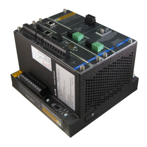
of individual meters, relays and recorders (Figure 1-1).
IQ Analyzer:
• Complies with rigid ANSI C12.16 Class 10 revenue
meter accuracy standard
• Provides true rms readings through the 50th harmonic
• Accurately measures nonsinusoidal waveforms up to
a 3.0 crest factor
• Displays even and odd multiples of fundamental
current and voltage through 50th harmonic
• Displays both magnitude and phase angle of the
harmonics
• Monitors neutral and ground conductors in addition to
3 phases
!
CAUTION
!
WARNING
TD 17530A
Page 2
Effective 5/98
A unique operator interface, which includes a gas
plasma display, easy to use “Meter Menu” screens and
detailed “Analysis” screens, permits an operator to
easily access a wealth of real time and recorded
information. The display provides the flexibility of
exhibiting large characters with high visibility and small
characters for detailed descriptions. All programming
can be accomplished through the faceplate or
communications port (Figure 1-2). The on-line Help
feature provides useful information on device operation,
programming and troubleshooting.
The IQ Analyzer directly monitors 3-phase lines to 600
Vac nominal without the need for external potential
transformers. External potential transformers are only
required above 600 Vac, even if the system is
ungrounded.
IQ Analyzer is comprised of the IQA-6000 Series and
IQA-6200 Series of system monitors. The IQA-6000
Series and IQA-6200 Series are similar in the features
offered except that graphic and transient triggering
abilities are also part of the IQA-6200 Series. Six different
IQ Analyzer configurations are available, three within the
IQA-6000 Series and three within the IQA-6200 Series.
Refer to Table 1.1 for specific style numbers.
IQA-6000 Series IQA-6200 Series
IQA6030: powered from IQA6230: Like IQA6030 except
three-phase line it with graphic and
monitors transient triggering
abilities
IQA6010: accepts separate IQA6210: Like IQA6010 except
source, single-phase with graphic and
120/240 Vac control transient triggering
power abilities
IQA6020: accepts 24/48 Vdc IQA6220: Like IQA6020 except
supply with graphic and
transient triggering
abilities
Figure 1-1 IQ Analyzer (Front View) Figure 1-2 IQ Analyzer (Rear View) with Optional IPONI
(INCOM Product Operated Network Interface)
Communication Module Installed
TD 17530A Page 3
Effective 5/98
1-2.1 COMPREHENSIVE INFORMATION
The IQ Analyzer displays the most comprehensive list of
metered parameters in its class. Multiple parameters,
such as currents of phases A, B and C, are displayed
simultaneously for more thorough real-time monitoring.
Custom screens can be configured to view a parameter
grouping, such as volts, amperes and power factor, for
convenience, or to concurrently observe their
relationships as conditions change.
1-2.2 HARMONIC DISTORTION ANALYSIS
Current and voltage distortion data are displayed by the
IQ Analyzer and/or accessible through the
communications port. This includes:
• % THD
• K-Factor
• Crest Factor
• CBEMA Factor
• Harmonic magnitudes through the 50th
• Harmonic phase angles through the 50th
A snapshot sample of this information may be activated
by user commands, discrete inputs, programmable
thresholds, or minimum/maximum updates to capture
distortion data during conditions of interest. To help
eliminate nuisance alarms, harmonic distortion
information can be captured and relay outputs activated
when THD exceeds a:
• Programmable percentage of fundamental
or
• Programmable magnitude, such as amperes,
threshold
1-2.3 EXTENSIVE I/O AND COMMUNICATIONS
CAPABILITIES
One analog and three digital inputs are provided to
interface with sensors and transducers. Three analog
output and four relay contacts are furnished to share
data with PLCs and control systems, and to actuate
alarms and control relays. Terminals are captive clamp
type and finger safe (Figure 2-2). With the
communications option, IQ Analyzer can be remotely
monitored, controlled and programmed.
1-2.4 DISTURBANCE INFORMATION
The 6200 Series Analyzer or with the communications
option and IMPACC Series III and Wave Form Display
software, a waveform analysis will construct waveforms
of up to 56 cycles of all currents and voltages, including
neutral and ground, to help troubleshoot undervoltage/
sag and overvoltage/swell conditions. For example, by
programming a reset threshold, the duration of the
voltage disturbance can also be indicated.
1-2.5 HIGH ACCURACY
Advanced electronic circuitry enables IQ Analyzer to
comply with the ridged ANSI C12.16 Class 10 accuracy
standard for revenue meters. In addition, accuracy is
maintained in applications with high distortion levels.
This includes systems exhibiting a 3.0 Crest Factor,
harmonics up to the 50th multiple of the fundamental,
and frequency variations.
1-2.6 OPERATIONAL SIMPLICITY
The IQ Analyzer’s “Meter Menu” makes commonly
viewed parameters easy to access and understand. For
additional information, the “Analysis” screens provide
comprehensive data on harmonic distortion, current/
power demands, trending and event/alarms. IQ
Analyzer also has a “Help” pushbutton to assist in
programming, troubleshooting and operating the device.
This manual is accurate to firmware version 1.16.
Cutler-Hammer reserves the right to add and/or
change features.
NOTICE
TD 17530A
Page 4
Effective 5/98
1-3 QUICK START
This section is intended to provide an operator with
enough basic information to put the IQ Analyzer into
service quickly, without reviewing all of the instructions
presented in this book. Even if the Quick Start approach
is successful, it is strongly recommended that the entire
book be reviewed. Taking full advantage of the wide
array of features offered by the IQ Analyzer cannot be
fully realized by using only the Quick Start approach.
This manual contains the following numbered sections:
1. Introduction/Quick Start.
2. Hardware Description. Itemizes the operator panel,
rear access area, external hardware, and
specifications
3. Operator Panel. Describes the function of LEDs,
display window, and pushbuttons.
4. Installation. Describes the mounting, wiring, initial
startup, and steps necessary to perform basic
metering.
5. Operation. Describes the functional details of
operation. These include: Meter Menu, help,
programmed settings, general setup, inputs and
outputs, analysis screens, reset screens, and
communications.
6. Programming. Describes the entry of programmable
settings. This includes the common programming
procedures of entering the password, moving
through the levels of screens, and a detailed
example. Also included are the Screens Trees, which
diagram the categories of settings.
7. Troubleshooting and Maintenance. Provides a
troubleshooting matrix of symptoms, probable
causes, and solutions. Also described are the steps
for removal, return, and replacement of the unit. For
further assistance contact the Advanced Product
Support Center at 1-800-809-2772 (APSC).
In addition, an Appendix and Glossary are also provided
as follows:
Appendix. Startup Setting Sheets. Provides a
summary of settings and a place to logically record
programming details
Glossary. Provides a reference for terms and
phrases as used throughout this publication.
1-3.1 QUICK START STEPS
Step 1: Review the Introductory Comments and
Safety, paragraph 1-1.
Step 2: Mount the IQ Analyzer as described in
paragraph 4-2.
Step 3: Wire the IQ Analyzer as described in
paragraph 4-3 using diagrams of Figures 4-9
to 4-34 as a reference.
Step 4: Follow the Initial Startup procedures of
paragraph 4-4 to apply power and setup basic
metering.
Step 5: Examine the metered values for consistent
currents, voltages, and power. As necessary,
refer to the Troubleshooting Guide, Table 7. 1.
The IQ Analyzer itself can help the diagnosis of
possible miswiring. Manually create an event with
the F3 (HARM) and F4 (NEW) soft-keys. Again using
the F1-F4 soft-keys, examine the fundamental (1st
harmonic) phase angles of Van, Vbn, Vcn, Ia, Ib, and
Ic. In a positive sequenced system, one expects the
phase angles of Van, Vbn, and Vcn to be 0° -120°
and +120°, respectively.
NOTICE
TD 17530A Page 5
Effective 5/98
Device Description Catalog No. Style No.
IQ Analyzer with self-powered three phase power module IQA6030 2D82302G01
IQ Analyzer with separate source power module IQA6010 2D82302G02
IQ Analyzer with dc power module IQA6020 2D82302G05
Self-powered, graphic displays and transient triggering IQA6230 2D82302G03
Separate Source, graphic displays and transient triggering IQA6210 2D82302G04
dc power module, graphic displays and transient triggering IQA6220 2D82302G06
IQ Mounting Flange IQFLANGE 5743B02G01
IQ Analyzer 36 inch extension cable IQACABLE 2107A55G02
IQ Analyzer 45 inch extension cable IQA45CABLE 2107A55G03
Self-powered three phase power module only IQA3PPM 8793C15G01
Separate source power module only IQASSPM 8793C07G0
dc source power module only IQADCPM 66C2065G01
Communication module IPONI 8793C36G01
Series III Software (200 devices) S3200 2091A75G11
Waveform Display Software WAVEDISP 8173A41G01
Portable IQ Analyzer IQA6210 PORT 4013115G01
Table 1.1 IQ Analyzer Ordering Information
➀
➀
An IQ Analyzer is supplied with a power module and a manual as standard. A communications module (IPONI), potential
transformers and current transformers are not supplied with the IQ Analyzer.

Other Eaton Measuring Instrument manuals

Eaton Crouse-hinds series User manual

Eaton

Eaton Crouse-hinds series User manual

Eaton xStorage Home Series User manual

Eaton

Eaton xStorage Home Series User manual

Eaton IQ 250 Guide

Eaton

Eaton IQ 250 Guide

Eaton Durant Eclipse Series User manual

Eaton

Eaton Durant Eclipse Series User manual

Eaton Moeller Series User manual

Eaton

Eaton Moeller Series User manual

Eaton IQ 35M Series User manual

Eaton

Eaton IQ 35M Series User manual

Eaton Cutler-Hammer IQ 300 Series Programming manual

Eaton

Eaton Cutler-Hammer IQ 300 Series Programming manual

Eaton IQ 200 User manual

Eaton

Eaton IQ 200 User manual

Eaton 1MM User manual

Eaton

Eaton 1MM User manual

Eaton RMD User manual

Eaton

Eaton RMD User manual

Eaton CMD User manual

Eaton

Eaton CMD User manual

Eaton Crouse-Hinds MTL Z230 User manual

Eaton

Eaton Crouse-Hinds MTL Z230 User manual

Eaton PDI WaveStar Infinity 2 Manual instruction

Eaton

Eaton PDI WaveStar Infinity 2 Manual instruction

Eaton Crouse-hinds series User manual

Eaton

Eaton Crouse-hinds series User manual

Eaton Power Xpert PXM 4000 Operating manual

Eaton

Eaton Power Xpert PXM 4000 Operating manual

Eaton Cutler-Hammer Enclosed IQ Manual

Eaton

Eaton Cutler-Hammer Enclosed IQ Manual

Eaton xComfort CSEZ-01/06 Manual

Eaton

Eaton xComfort CSEZ-01/06 Manual

Eaton Crouse-hinds series User manual

Eaton

Eaton Crouse-hinds series User manual

Eaton EMC3P-P2C1 User manual

Eaton

Eaton EMC3P-P2C1 User manual

Eaton RMQ compact solution Manual

Eaton

Eaton RMQ compact solution Manual

Eaton 2075 User manual

Eaton

Eaton 2075 User manual

Eaton Power Xpert Meter 2000 User manual

Eaton

Eaton Power Xpert Meter 2000 User manual

Eaton InsulGard User manual

Eaton

Eaton InsulGard User manual

Eaton Durant Eclipse Series User manual

Eaton

Eaton Durant Eclipse Series User manual

Popular Measuring Instrument manuals by other brands

Akron STYLE 9015 Instruction manual and parts list

Akron

Akron STYLE 9015 Instruction manual and parts list

PeakTech 3432 manual

PeakTech

PeakTech 3432 manual

Auber Instruments SYL-53X2P Supplementary manual

Auber Instruments

Auber Instruments SYL-53X2P Supplementary manual

LaserLiner TelePod Plus 330 cm manual

LaserLiner

LaserLiner TelePod Plus 330 cm manual

HP 1670A Series user guide

HP

HP 1670A Series user guide

SUTO S431 OEM Instruction and operation manual

SUTO

SUTO S431 OEM Instruction and operation manual

AEMC instruments K100 user manual

AEMC instruments

AEMC instruments K100 user manual

biosystems A25 Service manual

biosystems

biosystems A25 Service manual

Copper Mountain Technologies R60 Operating and programming manual

Copper Mountain Technologies

Copper Mountain Technologies R60 Operating and programming manual

UE Systems Ultraprobe 15000 Touch instruction manual

UE Systems

UE Systems Ultraprobe 15000 Touch instruction manual

Kobold DAG-A4T Series operating instructions

Kobold

Kobold DAG-A4T Series operating instructions

Ametek Davenport PET Plus user manual

Ametek

Ametek Davenport PET Plus user manual

HYDAC International FMMP Operating and maintenance instructions

HYDAC International

HYDAC International FMMP Operating and maintenance instructions

Hanna Instruments DiST HI 98302 quick start guide

Hanna Instruments

Hanna Instruments DiST HI 98302 quick start guide

ALGE-Timing Photocell PR1aW manual

ALGE-Timing

ALGE-Timing Photocell PR1aW manual

VOLTCRAFT IR-SCAN-350RH/2 operating instructions

VOLTCRAFT

VOLTCRAFT IR-SCAN-350RH/2 operating instructions

Kobold HND-F205 operating instructions

Kobold

Kobold HND-F205 operating instructions

HEIDENHAIN TS 640 Mounting instructions

HEIDENHAIN

HEIDENHAIN TS 640 Mounting instructions

manuals.online logo
manuals.online logoBrands
  • About & Mission
  • Contact us
  • Privacy Policy
  • Terms and Conditions

Copyright 2025 Manuals.Online. All Rights Reserved.