Eaton DualGuard-S ESF30 KV Service manual

Compact Fire-Resistant Cabinet Type DualGuard-S ESF30 KV
Mounting and Operating Instructions compact
Fire-resistant cabinet type DualGuard-S ESF30 KV
Target group: qualified electricians according to DIN VDE 0105 Part 1
Mounting and Operating Instructions DualGuard-S ESF30 KV

2Mounting and Operating Instructions DualGuard-S ESF30 KV 40071860406 (A) March 2022 www.eaton.com
Content
Content
1 Important notes ........................3
1.1 General information .....................3
1.2 Explanation of symbols. . . . . . . . . . . . . . . . . . . 3
1.3 Information on the assembly and installation
instructions ......................4
1.4 Other applicable documents ..............4
1.5 Liability, warranty and declaration of surrender 4
1.7Spare parts ............................4
1.8 Disposal ..............................4
2 Safety .................................4
2.2 Contents of the assembly and installation inst-
ructions .................................5
2.3 Modifications and conversions to the unit....5
2.4 Responsibility of the operator .............5
2.5 Requirements for the personnel ...........5
2.6 Occupational safety .....................5
3 Technical data ..........................5
4 Layout ................................6
4.1 DualGuard-S ESF30 SOU5 and SOU4 .......6
4.1.1 Components DualGuard-S ESF30 SOU5 and
SOU4 .........................6
4.1.2 Drawings DualGuard-S ESF30 SOU5 and
SOU4 .........................6
4.2 DualGuard-S ESF30 SOU3 ................6
4.2.1 Components DualGuard-S ESF30 SOU3 ...6
4.2.2 Drawings DualGuard-S ESF30 SOU3 ......6
4.3 DualGuard-S ESF30 SOU2 ................7
4.3.1 Components DualGuard-S ESF30 SOU2 ...7
4.3.2 Drawings DualGuard-S ESF30 SOU2 ......7
4.4 DualGuard-S ESF30 SOU1 ................7
4.4.1 Components DualGuard-S ESF30 SOU1 ...7
4.4.2 Drawings DualGuard-S ESF30 SOU1 ......7
5 Transport ..............................8
5.1 The most important aspects of transport in
brief ...........................8
6 Assembly and installation
DualGuard-S ESF30 SOU5, SOU4, SOU3,
SOU2, SOU1 .....................9
6.1 Wall mounting .........................9
6.2 Inserting the cables .....................9
Notes 10 Attention!
Danger of
tipping over

3
Mounting and Operating Instructions DualGuard-S ESF30 KV 40071860406 (A) March 2022 www.eaton.com
1 Important notes
1 Important notes
1.1 General information
Installation work may only be carried out by qualified elec-
tricians (cf. DIN VDE 0105 part 1, the accident prevention
regulation Accident Prevention Regulation BGV A3 of the
main of the Employer‘s Liability Insurance Associations or
analogous regulations and directives of the country in which
the system is installed and operated). Other persons may
carry out the activities described in this manual only if they
have been properly and professionally instructed, and have
received proper instruction,
• their tasks and activities have been precisely defined and
understood.
• the activities are carried out under the supervision and
control of
• competent personnel.
Observe:
• the requirements of the usability certificates
• the regulations of the MLAR, MBO, technical building
regulations
• the extended documentation obligations resulting from the
• amendment of the MBO.
• all instructions for maintenance contracts!
• the instructions in the safety data sheets for building
materials!
• Keep the swivel area of the door free and always keep
the door closed!
• Only use the system when it is in proper condition!
• For installation, operation and maintenance, the respective
accident prevention and DIN/VDE regulations must be
observed.
• The area of application of the products e.g.according to
the proof of usability must be checked by the customer.
• Impairment of the stability of the system when doors
are open if the system has not yet been screwed to the
building structure.
IMPORTANT NOTE:
• The operator is required by the applicant of a general buil-
ding authority approval/general type approval
• general building approval must inform the operator in
writing that the fire protection system
• that the fire protection system only meets the require-
ments of fire resistance only when closed. This has been
done herewith.
• Improper installation may impair the protective function.
• Screw connections to the building may only be made with
approved, suitable screws/dowels.
• The suitability of the screws/dowels must be checked
depending on the building.
• The enclosures must not be glued, painted or otherwise
coated.
• They must not be damaged (holes, screws) on the corpus.
(holes, screws).The locking systems must not be changed
or exchanged.
• When working with these assembly and installation
instructions the following instructions, marked with an
attention symbol and a symbol and a password, the follo-
wing instructions to be observed.
1.2 Explanation of symbols
Important safety instructions in these operating instructions
are marked with symbols.
NOTE:
Gives important tips and advice on the procedure or handling
of the described devices or system parts.
ATTENTION!
Indicates sources of danger that may be the cause of da-
mage to plants or plant damage to installations or parts of
installations as well as environmental can be.
WARNING!
Draws attention to sources of danger that can cause injury
to persons or persons or serious damage to installations or
parts of installations and serious environmental damage.
DANGER!
Draws attention to sources of danger that may cause life-
threatening injuries to persons or serious damage, which
indirectly pose a danger to persons or the environment.
WARNING!
The illustrations in these assembly and installation instruc-
tions are only intended to illustrate the described circum-
stances.
Wherever
• work is carried out with dimensional accuracy or
• precise drawings adapted to the special features on site,
the drawings are required, the drawings that have been dra-
wings that have been specially prepared for the installation.
WARNING!
Only carry out work for which you have sufficient profes-
sional and have been instructed in the local and operational
conditions!
In the case of extensions, conversions, repairs or work
that is work that is not described in these instructions are
to be carried out by specially trained specialist and service
personnel (of the manufacturer CEAG or sales and service
companies authorised by CEAG)!

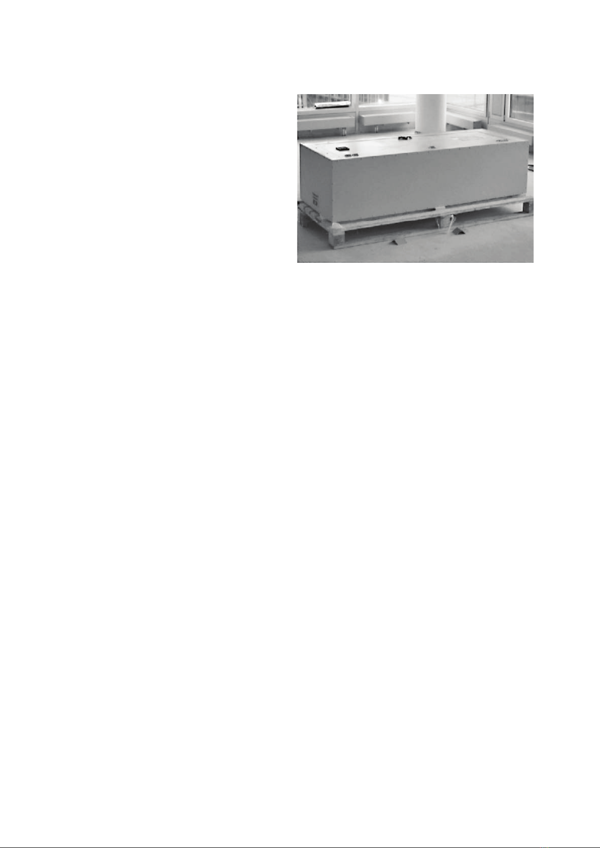
4Mounting and Operating Instructions DualGuard-S ESF30 KV 40071860406 (A) March 2022 www.eaton.com
2 Safety
1.3 Information on the assembly and installa-
tion instructions
These installation and operating instructions are intended
for practical use and must be made available to the user/
installer at the place of use of the fire protection system.
They do not release the installer from the obligation to comply
with all details and specifications of the usability and to use
the systems immediately at the check the delivery. Keep
these installation and and operating instructions inside the
fire protection system. Safe and proper functioning of the
system is only guaranteed if the following instructions and
safety information are followed. A warranty with regard to
the IP class is only possible with proper installation. Please
keep these assembly and installation instructions carefully, as
they are an integral part of the supplied electrical distribution
board. Safe and approved function is only ensured if these
instructions are observed.
1.4 Other applicable documents
In addition to the assembly and installation instructions the
installation and operating instructions of the central battery
systems DualGuard-S must be observed.
1.5 Liability, warranty and declaration of
surrender
• In order to ensure optimal functioning of our products the
installation instructions must be observed.
• CEAG‘s warranty extends to the products supplied.
• Modifications or alterations to the design may only be
carried out after consultation with CEAG, otherwise the
approval/warranty will expire.
• The warranty for installation services is to be assumed by
the installer.
• Warranty and liability claims for personal injury and are
excluded if they are due to one or more of the following
causes:
• Fire protection enclosures are not used as intended.
• Improper installation, commissioning, operation and
maintenance.
• Non-observance of the instructions regarding transport,
storage, operation and assembly.
• Unauthorised structural modifications to the fire protection
enclosures.
• Inadequate monitoring of the safety devices to be installed.
improper repairs.
• catastrophes caused by third parties and force majeure.
Property rights
To safeguard innovation and design utility models have been
deposited.
General
We expressly reserve the right to make technical changes
that serve to improve the enclosures or that are caused by
legal changes- even without separate notification.
All information and notes in these assembly and installation
instructions have been compiled taking into account the ap-
plicable regulations, the state of the art and our many years
of knowledge and experience.The assembly and installation
instructions must be kept in the immediate vicinity of the unit
and accessible at all times to all persons working on or with
the unit. These assembly and installation instructions must
be read carefully before starting any work on or with the unit!
1.6 Copyright protection
The assembly and installation instructions are to be treated
confidentially.They are intended exclusively for persons wor-
king on and with the unit. All information regarding content,
texts, drawings, pictures and other illustrations are protected
in the sense of the copyright law.
1.7 Spare parts
Only use original spare parts from the manufacturer. Incorrect
or faulty spare parts can lead to damage, malfunctions or total
failure of the unit. If unapproved spare parts are used, the
following will be forfeited all warranty, service, compensation
and liability claims.
1.8 Disposal
Unless a take-back or disposal agreement has been disas-
sembled components for recycling after proper disassembly.
2 Safety
At the time of its development and manufacture, the app-
liance in accordance with the applicable, recognised rules
of technology and is considered safe to operate. However,
hazards may arise from this unit if it is used by untrained
personnel, improperly or not or if it is not used for the inten-
ded purpose. The special regulations in this manual must
be observed. Observe the standards and regulations of the
VDE, the DIN.
Make sure
• that the requirements of the fire protection authorities are
observed and are complied with,
• that the requirements of the building supervisory authori-
ties are observed are complied with,
• that the conditions of the technical building regulations
for your for your federal state are complied with, take into
account the Model Cable Systems Directive (MLAR).
• that the installation of the enclosure increases the fire re-
sistance duration and the stability of the fire wall to which
the enclosure has been reduced.
• that the enclosure does not show any damage, e.g. cracks
or displacements in the insulation,
• that the enclosure is always closed during operation,
• that the swivel area of the door is always free,
2.1 Intended use

5
Mounting and Operating Instructions DualGuard-S ESF30 KV 40071860406 (A) March 2022 www.eaton.com
2 Safety
2.4 Responsibility of the operator
These operating instructions must be kept in the immediate
vicinity of the unit and must be accessible at all times to
persons working on and with the unit. The unit may only be
operated if it is in a technically perfect and operationally safe
condition.The unit must be checked for integrity before each
start-up. The information in the operating instructions must
be followed completely and without restriction!
2.5 Requirements for the personnel
These operating instructions must be read and understood in
the immediate vicinity of the appliance and only authorised
and trained personnel may work with the appliance. The
personnel must have received instruction on any hazards that
may occur. Qualified personnel are those who, on the basis
of their technical training, knowledge and experience as well
as knowledge of the relevant regulations, are able to assess
the work assigned to them and recognise possible dangers.
2.6 Occupational safety
By following the safety information and instructions in this
manual can prevent personal injury and damage during work
with and on the unit can be avoided.
The electrical distribution board with function maintenance
type DualGuard-S ESF30 is used for the battery-supported
monitoring and power supply for emergency lighting. It may
only be:
- used as intended and
- be used in a safe and proper condition.
used in a safe condition. When handling the products and
for the correct the cable entry, please follow these operating
instructions exactly. Any other use is considered improper.
CEAG Notlichtsysteme is not liable for any damage or con-
sequential damage resulting from this.
2.2 Contents of the assembly and installation
instructions
Every person who is assigned to carry out work on or with
the unit must have read and understood the operating instruc-
tions before starting work on the unit.This also applies if the
person concerned has already worked with such a device
or similar devices or has been trained by the manufacturer.
2.3 Modifications and conversions to the
unit
To avoid hazards and to ensure optimum performance, no mo-
difications, additions or conversions may be made to the unit
that have not been expressly approved by the manufacturer..
Type
DualGuard-S
ESF30 SOU5
DualGuard-S
ESF30 SOU4 IO
DualGuard-S
ESF30 SOU3
DualGuard-S
ESF30 SOU2
DualGuard-S
ESF30 SOU1
Certificates
Empty enclosure DIBT DIBT DIBT DIBT DIBT
Fire exposure
from outside (min)
30 30 30 30 30
Housing data
Housing Fire protection panels Fire protection panels Fire protection panels Fire protection panels Fire protection panels
Degree of protection IP54 IP54 IP54 IP54 IP54
Protection class II II II II II
Dimensions
(H x W x D in mm)
1228 x 478 x 295 1228 x 478 x 295 928 x 478 x 295 778 x 478 x 295 628 x 478 x 295
Weight (kg) Raw cabinet 103 103 80 69 60
Closing Swivelling lever with
Double pin
Swivelling lever with
Double pin
Swivelling lever with
Double pin
Swivelling lever with
Double pin
Swivelling lever with
Double pin
Electrical data
Rated voltage 230 V 50/60 Hz 230 V 50/60 Hz 230 V 50/60 Hz 230 V 50/60 Hz 230 V 50/60 Hz
Number of module slots 54321
Max. Cable cross-section
End circuits (mm²)
444 4 4
Max. Individual conductor
cross-section (mm²)
10 10 10 10 10
Max. Total conductor
cross-section (mm²)
143 248 113 98 83
3 Technical data

6Mounting and Operating Instructions DualGuard-S ESF30 KV 40071860406 (A) March 2022 www.eaton.com
4 Layout
4.1 DualGuard-S ESF30 SOU5 and SOU4
4.1.1 Components DualGuard-S ESF30 SOU5
and SOU4
4.2 DualGuard-S ESF30 SOU3
4.2.1 Components DualGuard-S ESF30 SOU3
4.1.2 Drawings DualGuard-S ESF30 SOU5
and SOU4
4.2.2 Drawings DualGuard-S ESF30 SOU3
(1228)
(478)
(295)
A
A
(200)
(950)
(139)
(139) (139)
(139)
(1228)
(478)
(295)
A
A
(200)
(950)
(139)
(139) (139)
(139)
(928)
A
A
A-A (1 : 5)
(295)
(478)
(200)
(139) (139)
(139)
(139)
(650)
(928)
A
A
A-A (1 : 5)
(295)
(478)
(200)
(139) (139)
(139)
(139)
(650)
(928)
A
A
A-A (1 : 5)
(295)
(478)
(200)
(139) (139)
(139)
(139)
(650)
(1228)
(478)
(295)
A
A
(200)
(950)
(139)
(139) (139)
(139)
1Enclosure
2Switch-over modules
SOU CG-S 2 x 4 A
1Enclosure
2Switch-over modules
SOU CG-S 2 x 4 A
4 Layout
1
1
1
2 2
2

7
Mounting and Operating Instructions DualGuard-S ESF30 KV 40071860406 (A) March 2022 www.eaton.com
4 Layout
(778)
A
A
A-A (1 : 5)
(295)
(478)
(200)
(139)
(139)
(139)
(500)
(139)
(778)
A
A
A-A (1 : 5)
(295)
(478)
(200)
(139)
(139)
(139)
(500)
(139)
(628)
(478)
(295)
A
A
(200)
(350)
(139) (139)
(139)
A-A (1 : 5)
(139)
(628)
(478)
(295)
A
A
(200)
(350)
(139)
(139)
(139)
A-A (1 : 5)
(139)
(628)
(478)
(295)
A
A
(200)
(350)
(139) (139)
(139)
A-A (1 : 5)
(139)
(778)
A
A
A-A (1 : 5)
(295)
(478)
(200)
(139)
(139)
(139)
(500)
(139)
4.3 DualGuard-S ESF30 SOU2
4.3.1 Components DualGuard-S ESF30 SOU2
4.3.2 Drawings DualGuard-S ESF30 SOU2
1Enclosure
2Switch-over modules
SOU CG-S 2 x 4 A
4.4 DualGuard-S ESF30 SOU1
4.4.1 Components DualGuard-S ESF30 SOU1
4.4.2 Drawings DualGuard-S ESF30 SOU1
1Enclosure
2Switch-over modules
SOU CG-S 2 x 4 A
11
22

8Mounting and Operating Instructions DualGuard-S ESF30 KV 40071860406 (A) March 2022 www.eaton.com
5 Transport
5 Transport
5.1 The most important aspects of transport
in brief
• Delivery of the fire protection system on a transport pallet
• The systems must be inspected immediately upon delivery
and any visible defects must be noted immediately on the
consignment note.
• Defects must be reported in writing (no later than 5 working
days after delivery).
• The transfer of risk is upon delivery. Defects which have
arisen due to onward transport of the systems, are exclu-
ded from subsequent fulfilment.
• Transport of the fire protection system to the place of use
with a suitable forklift truck on a transport pallet, protective
corners and strapping
• Improper transport (hard knocks, transport without air
suspension, repeated reloading, one-sided loading when
loading on one side during installation, etc.) can have an
effect on the fire protection function (damage to the fire
protection panels or their connections).
• If the system has to be moved, this must be done only be
carried out evenly and over the entire surface.
• The system must be closed off.

9
Mounting and Operating Instructions DualGuard-S ESF30 KV 40071860406 (A) March 2022 www.eaton.com
6 Assembly and installation DualGuard-S ESF30 SOU5, SOU4, SOU3, SOU2, SOU1
4 x fasteners
1 x double bit key
1 x instruction manual
1 x maintenance checklist (
2. Lift the system with a suitable lifting device e.g. scissor
lift truck to the specified installation height.
3. Align the manifold vertically on the wall and secure it
with the the pre-drilled holes in the back panel/fixing lug.
Observe the diagonal dimension. Do not drill into the rear
wall! Caution: Danger of breakage!
4. Component thickness
6 Assembly and installation
DualGuard-S ESF30 SOU5, SOU4, SOU3,
SOU2, SOU1
6.1 Wall mounting
General notes
Uneven wall surfaces that are not touched by the fire pro-
tection system, are to be (Crystal-CEL), provided that these
have a gap of more than 5 mm or if smoke is likely to escape
in the event of a fire. Walls must be level and plumb.
Normal tolerances of the walls/plaster must be compensated
for in such a way that smoke- and fire-proof installation is
possible.
For the installation on the wall, only the materials described
in the the „General Building Inspectorate Approval“ may be
used. The wall on which the distributor is to be mounted
must have sufficient load-bearing capacity. The fire resi-
stance of the supporting walls should be at least as high as
that of the distributor. With the help of the enclosed screw
anchors, DualGuard-S ESF30 can be easily screwed on via
the fastening holes in the housing - in both cracked and
non-cracked concrete. A distance of at least one metre from
neighbouring installations such as gas or water is required.
In In the vicinity of doors, a distance corresponding to the
door must be maintained.
1. Check the accessories for completeness:
6.2 Inserting the cables
The cable entry as a system component of the electrical
enclosure consists of:
a) a metal cover,
b) the intumescent and
endothermic areas The metal cover with different dimensi-
ons, depending on the type of distribution board, is provided
with holes.The cables are to be inserted through these holes.
To do this, the insulation layer visible through the holes must
be removed with a drill (with a drill bit approx. 2 mm smaller
than the diameter of the cable).This makes it easier to insert
the cable.When piercing the red or blue intumescent, make
sure that the the red or blue intumescent must be guided
straight. To achieve strain relief for the cables, a cable rail is
to be mounted on the equipment support inside the cabinet
and directly in front of the cable inlet outside the cabinet and
attach the cables to it.
The exact drilling depth depends on the dowel length and
is to be be determined as follows: Required drilling depth
= anchor length
- component thickness + 10 mm
- Minimum anchoring depth of the enclosed dowels: 70 mm;
- Drill diameter: 10 mm
5. Suck out the drill dust, drive in the dowel- through-fixing
(screw head flush) and tighten the screw screw with a
suitable wrench/screwdriver- do not overtighten! tighten
- do not overtighten! Do not countersink the screw head
into the into the material.
6. Push the plastic caps onto the fastening anchors and press
them firmly. and press firmly. (optional)
7. Spray the plastic caps of the fastening anchors with fire
protection putty to around the plastic caps of the fastening
anchors to ensure the protection class. (optional)

10 Mounting and Operating Instructions DualGuard-S ESF30 KV 40071860406 (A) March 2022 www.eaton.com
Notes
Notes

11
Mounting and Operating Instructions DualGuard-S ESF30 KV 40071860406 (A) March 2022 www.eaton.com
Notes
Notes

Eaton is a registered trademark.
All other trademarks are the property of
their respective owners.
The aim of Eaton is to provide a reliable, efficient and safe
power supply where it is needed most. Eaton's experts have
comprehensive in-depth specialist knowledge in the area
of energy management in the most diverse of sectors and
therefore they are able to provide customer-specific, integrat-
ed solutions to meet the most challenging demands of its
customers.
It is our highest priority always to find the right solution for
every application. Our stakeholders therefore expect more
than just innovative products. Companies turn to Eaton
because they know that individual support and the success of
our customers is always our top priority. For more information
visit www.eaton.com.
Eaton Industries Manufacturing GmbH
Electrical Sector EMEA
Route de la Longeraie 7
1110 Morges, Switzerland
Eaton.eu
CEAG Notlichtsysteme GmbH
Senator-Schwartz-Ring 26
59494 Soest, Germany
Tel.: +49 (0) 2921 69-870
Fax: +49 (0) 2921 69-617
Web: www.eaton.com
© 2022 Eaton
All rights reserved.
Printed in Germany
Order no. 40071860406 (A)
Publication no. MN451102EN
March 2022
Table of contents
Other Eaton Safety Equipment manuals

Eaton
Eaton RMQ-Titan C22-PV Series User manual

Eaton
Eaton CEAG GuideLed 10011 LED CG-S Service manual

Eaton
Eaton Crouse-hinds series User manual

Eaton
Eaton K1121V11 Manual

Eaton
Eaton Atlantic CG-S Service manual

Eaton
Eaton FlexiTech User manual

Eaton
Eaton Ex-TRA 100 User manual

Eaton
Eaton CEAG 22011 LED CG-S Series Service manual

Eaton
Eaton FlexiTech SE CGLine+ Series User manual

Eaton
Eaton BG3 User manual