K1121V11
Eaton
Wheatley Hall Road, Doncaster, South Yorkshire, DN2 4NB
Sales
T: +44 (0)1302 303303
F: +44 (0)1302 367155
E: sales@cooper-ls.com
General
+44 (0)1302 321541
+44 (0)1302 303220
technical@cooper-ls.com
International Sales
+44 (0)1302 303250
+44 (0)1302 303251
export@cooper-ls.com
Safe Operation
1. Check the rating label for voltage and frequency before connecting this
luminaire to the electrical supply.
2. Ensure that the mains supply is switched off when working on this
luminaire, whether installing or carrying out any other servicing.
3. Do not mount luminaire on or close to readily flammable materials.
4. To prevent damage to driver, do not mix with conventional magnetic
ballasts on the same electrical circuit.
5. Where use in more onerous situations is required, e.g. In part-
completed buildings before “drying-out” is completed, or areas where
ambient temperatures are outside the normal temperature range, then
consult our Sales Office.
6. The light source contained in this luminaire shall only be replaced by the
manufacturer or his service agent or a similar qualified person.
7. When used as intended this product complies with the EMC Directive
2014/30/EU and Low Voltage Directive 2014/35/EU.
Servicing and Disposal
1. At commissioning and handing over of installation ensure that a copy of
these instructions is presented to the authority responsible for the
operation and maintenance of the luminaries.
2. Servicing, e.g. cleaning, must only be carried out after the electricity
supply has been switched off. It must not be assumed that luminaries
with LEDs not lit are switched off, always check before servicing.
3. Cleaning should be carried out at regular intervals to ensure that dirt
does not accumulate to an extent that will impair the thermal safety or
optical performance of the luminaire. Regular cleaning will also ensure
that the optical performance of the luminaries is maintained.
4. Avoid touching the LED array surface. To clean - Blow surface with
either dry air or nitrogen gas.
5. At the end of life the luminaire is classed as WEEE under directive
2012/19/EU and should be disposed of in accordance with local
legislation.
Luminaire Service
Luminaire Cleaning
End of Life and Components Disposal
WEEE
February 2020
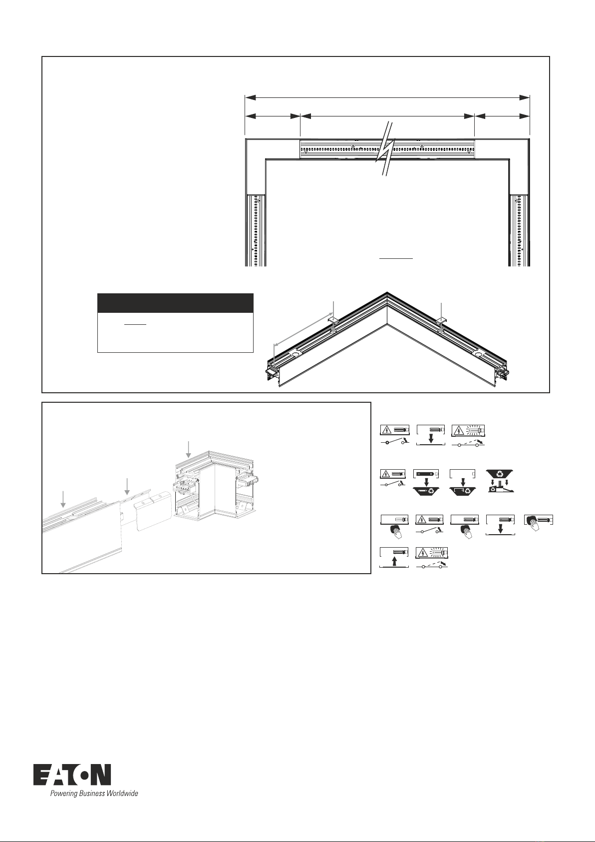
Leat
Leat
Connecting Plates
Leat Corner Remove front cover from corner
Offer up the Leat Corner up to
the continuous Leat with the
Connecting Plates in position
holding both parts together (See
‘Connector Plates’ in step 4).
Screw the plates to both parts,
ensuring they are butted up
together.
Connect the plug and socket from
both parts. Corner through wiring
can be swapped around to switch
corner direction.
Fix front cover back on the Leat
Corner
Leat Corner (100mm) - Sold Seperatley
Leat Corner (500mm) - Sold Seperatley
A (External)
B
A = Overall Length (measured)
B = Diffuser Cut Length
(A - 0.280m) x 0.9994 = B
e.g. 10.068m - 0.280m = 9.788m
9.788m x 0.9994 = 9.782m
0.140m 0.140m
Follow steps ‘a, b, c, d’ and ‘f’ under
‘Continuous Installation’ on page 3.
After step ‘f’ cut the diffuser, using the
formula on the right to ascertain the
diffuser cut length
Instruction Manual - K1121V11
Suspension Wire
Location
Suspension Wire
Location
270mm
Fit both suspensions wires as
before, over the 21mm diameter
holes.
!! CRITICAL TO QUALITY !!