
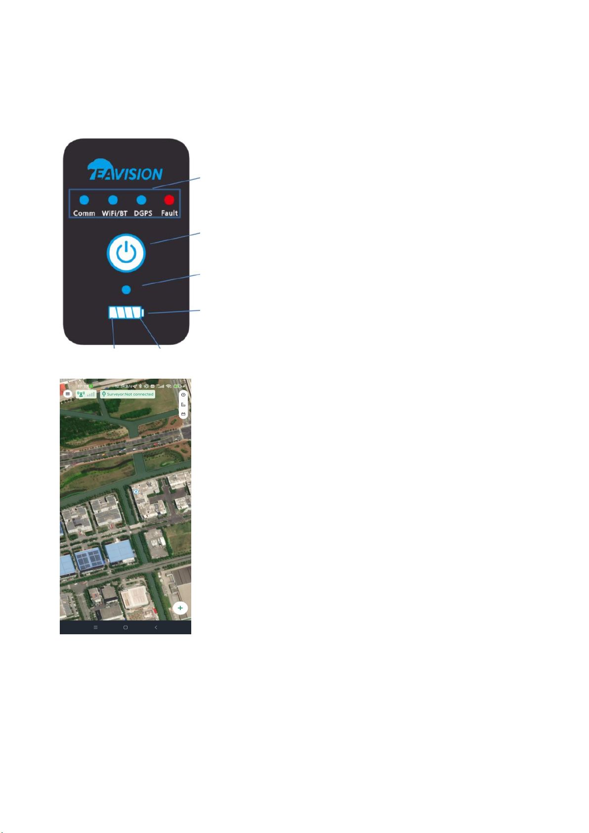
6. low battery indicator
(1) Working status: Low battery (estimated remaining usage time<=30min) ,Batt1 keeps flashing (on for
1s, off for 1s), and stops flashing when charging;
(2) Off status: Low battery (estimated remaining usage time<=30min) ,Batt1 keeps flashing (on for 1s, off
for 1s),within 3s of battery display keep flashing;
7. Function LED introduction
Functional module LEDs include Comm LED, WiFi/BT LED, DGPS LED, and Fault LED.This part mainly
introduces the working display and related faults of the first three LEDs, and the next part mainly introduces
fault information and LED display when warning or module failure occurs.
In the application of the function module, the default is the following three cases.
When the device is working, the online mode and offline mode will be placed on the ground
station (base station) App for switching operations;
(1) Comm LED disaplay
When there is a communication failure, such as communication failure or communication
disconnection, the communication LED + fault LED flashes synchronously;
(2) WIFI/BT LED disaplay
BT is enabled by default when the device is working。The user selects the device to be connected by
displaying the scanned device information on the App.
1Before WiFi/BT is not connected, the LED does not light up;
2After the BT connection is successful (WiFi is not in use), the LED flashes;
3When the WiFi setting is successfully connected (BT is not connected), the WiFi/BT LED is always
on;
4BT performs pairing and connection process through the device information displayed on the App:
If only one device is scanned, pair it directly (no manual operation required);
If multiple devices are scanned, the App will prompt you to select a paired device;
5BT pairing failed:
WiFi/Bluetooth LED malfunction:
Such as WiFi/Bluetooth failure (Wifi turn-on failure, Bluetooth turn-on failure or WiFi can't
find SSID network), WiFi/Bluetooth LED + Fault LED flashes synchronously;
In the event of a WiFi/Bluetooth LED malfunction:
The app prompts accordingly, and the fault LED does not flash.
a. the device is not bound to the drone or registered in the background;
b. BT pairing on the mobile phone fails;
c. Pairing failure due to wrong WiFi name or WiFi password.
(3) DGPS LED dsaplay
1RTK accuracy: LED is always on;
2High precision, common precision, low precision: LED flashes;
3When GPS is off: always off;
4When the GPS fails (the app will prompt or broadcast the cause of the failure synchronously) (such
as unable to enter the positioning) DGPS LED + fault LED Flashes in sync.


 user manual")
