EBS 2500 Instruction sheet
EBS Ink-Jet Systeme GmbH
D-51588 Nümbrecht-Elsenroth, Germany
Alte Ziegelei 19-25
++49 (0)2293-939-0
++49 (0)2293-939-3
www ebs-inkjet de
e-mail
mail@ebs-inkjet de
signature: 2010/02/00086#1 EN March 24, 2010
No. of pages
4
1
EBS-2500 Printer – Installation and First Start up
K
1
7
0
0
9
7
-
0
0
0
POWER SOCKET
NETZEINGANG
AC IN 100 – 240 V
~
USB
SHAFT LANFOTO /
PHOTO
EBS
Ink-Jet Systems
®
6
7
18
19
4
4
12
2
1
6
7
8
5
4
3
1
21
11
14
15
16
17
13
20
22
11
10
9
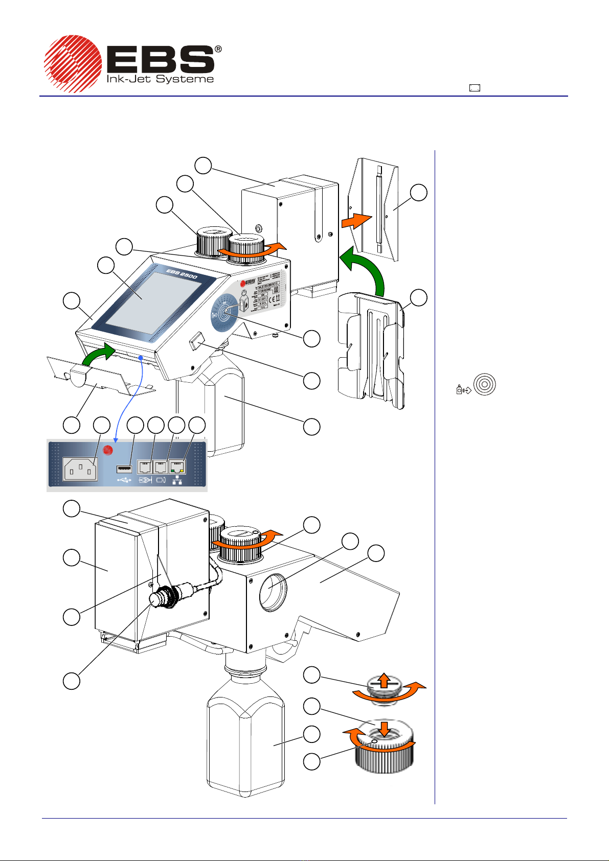
Unscrewing filter
Screwing filter in
Printer system components:
1. Printer controller with ink system.
2. Control panel LCD display.
3. Seat where bottle 23 is fixed.
4. Ink system vent valve with air
filter 21.
5. Ink pot cap.
6. Print head.
7. Protection for securin print head
nozzles a ainst mechanical
exposure and ink spill in case of
tilt or shock durin carria e.
8. Head slide to ensure that objects
to be labelled are precisely
uided and hit no print head
ed e.
9. Ink bottle transponder reader
(marked with symbol
IMS
).
10. Power switch.
11. Blue bottle for ink slops.
12. Cover for protectin back panel
connection sockets.
13. Mains socket.
14. USB port.
15. Socket for external photo-
detector.
16. Socket for conveyor shaft-
encoder.
17. Ethernet socket.
18. Photo-detector holder.
19. External photo-detector.
20. Pocket in the left wall of controller
to store unscrewed cap 5.
21. Filter of air sucked into ink
system.
22. Indicator of valve 4 position.
23. Ink bottle (a smaller capacity
starter bottle of ink is supplied
to ether with printer).
24. Stand for fixin printer to.
25. Controller handle for stand 24.
Fig. 1
EBS Ink-Jet Systeme GmbH D-51588 Nümbrecht-Elsenroth, Germany, Alte Zie elei 19-25 +49 (0)2293-939-0, +49 (0)2293-939-3 e-mail: mail@ebs-inkjet.de
4
signature: 2010/02/00086#1 EN ed. March 24, 2010
2
NOTE!
In order to use the printer characteristics fully, please follow all the recommendations contained in this
description. If any of the hints is not followed, a malfunction of the printer may occur or part of the printer's
functionality may be lost, whereas in extreme cases permanent damage that is not covered by guarantee
may occur.
Climatic conditions: operating temperature from +5°C to +40°C,
relative humidity up to 90% without condensation.
Mechanical conditions: vibration of max. 1 g, at max. 10 Hz, impact of max.1 g, over max. 2 ms.
Tools required: cross point screwdriver, 5 mm imbus key
I MECHANICAL INSTALLATION OF PRINTER IN WORKPLACE
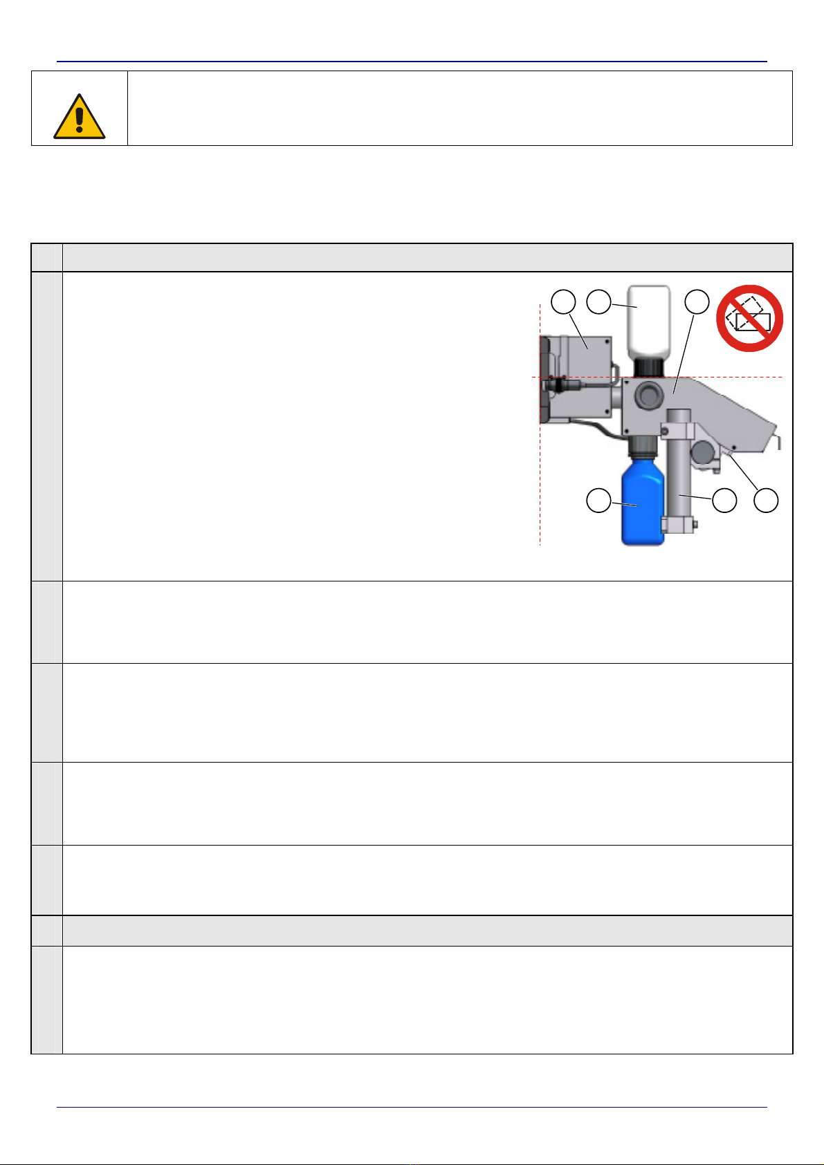
STEP 1
Install the printer on stand 24 in any convenient position in a
place that is free from vibration, shocks, excessive dust,
smoke and dirt as well as from aggressive or inflammable
vapours and gases.
If the printer is to be operated in a heavily dusty or
contaminated environment, please consider whether an
additional filter should be used in order to protect vent valve
4or whether a cover allowing free airflow should be installed
(ask your dealer for optional accessories).
Install and operate the printer in such a position that the line
determined by the top housing edge of controller 1shows the
HORIZONTAL DIRECTION, whereas the butting face of the
head shows the VERTICAL DIRECTION (see Fig. 2).
NOTE: The printer must not be tilted in any direction by
greater an angle than 30°while it is being installed
and operated.
HORIZONTAL
DIRECTION
VERTICAL
DIRECTION
11
23
6
1
24
25
Fig. 2
STEP 2
Install internal photo-detector 19 in holder 18 on print head 6or in any other place that will allow
you to release printing conveniently within the reach of photo-detector cable (see STEP 3). The
holder can be put on the other side of the head, if need be, by unscrewing the holding down bolts
and reversing the holder 18.
STEP
3
(
Optional)
You can fix an (external) photo-detector in a required place and attach it to connection socket 15
which is on the back panel.
You can also install a conveyor speed converter, a so called shaft-encoder, in a convenient place
on the conveyor on which objects to be labelled will move, so that the converter is driven by the
conveyor. Connect the shaft-encoder to socket 16 which is on the back panel.
STEP 4
Remove protection 7and screw in head slide 8in place of it. Install cover 12. Screw blue bottle
11 to the printer bottom to collect ink slops (make sure that the printer is not tilted by greater an
angle than 30°from the vertical direction). Remove protective film from panel LCD 2.
NOTE: The use of the slide is obligatory and vital for the proper operation of the printer!
STEP 5
Connect the controller feeder cable to socket 13 and to a mains socket and then start the printer
– by pressing switch 10 on the right wall of printer controller 1for a short time. Wait about 60
seconds for the printer system to start.
II MAKING READY FOR PRINTING
STEP 6
Check whether air filter 21 situated in vent valve 4is clean. The filter is unscrewed and screwed
in as it is shown in Fig. 1.
If the filter is dirty, clean it (see Basic Service Hints below). When the filter is clean, open valve 4
by turning the valve cap by about 15° counter clockwise - see Fig. 1 (the valve is open when
mark 22 on valve 4indicates the PRINTING position).

EBS Ink-Jet Systeme GmbH D-51588 Nümbrecht-Elsenroth, Germany, Alte Zie elei 19-25 +49 (0)2293-939-0, +49 (0)2293-939-3 e-mail: mail@ebs-inkjet.de
4
signature: 2010/02/00086#1 EN ed. March 24, 2010
3
STEP 7
The ink system pot is protected with a cork. Unscrew cork 5from bottle seat 3carefully and
remove it (the direction of unscrewing is shown in Fig. 1).
Place the cork in special pocket 20 in the left wall of the controller housing.
STEP 8
Remove the aluminium foil that protects the cap of starter bottle 23.
Then screw the starter bottle into bottle seat 3. No turning of the bottle upside down makes ink
spill as the bottle is equipped with a protective valve.
STEP 9
Follow a purging procedure in order to vent the printer. Press the [Service] button on panel LCD
2and select the right type of purging. Meaning of the buttons:
[Purge] – starts the short purging procedure (if the [Purge] button is pressed many times, the
short purging operation lasts longer),
[Long purge] – starts the long purging procedure,
[Stop] – stops purging;
The starter bottle allows you to fully purge the printer for the first time.
When the printer is started for the first time (e.g. after carriage), the long purge procedure
should be fully followed.
III INSTALLING INK BOTTLE
STEP 10
Put a new bottle of ink to place 9as shown on sticker in order to get the ink verified and
approved by the printer. After the information about ink has been scanned, message icon
appears in the right top corner of panel 2. Press the icon to read the bottle approval message.
NOTE: Every bottle can be verified and approved only once.
STEP 11
Unscrew the starter bottle from socket 3carefully and remove it (the direction of unscrewing is
shown in Fig. 1). Remove the aluminium foil that secures the cap of a new bottle and then screw
the new bottle into socket 3. Follow the short purging procedure by pressing the [Purge] button
from the "service” level.
STEP 12
Several test prints can be made (start printing by pressing the [Start] button from the "service" or
"printer control” levels). If the print quality appears unsatisfactory, a purging procedure can be
repeated.
STEP 13
The printer is ready for operation when all nozzles write properly during test printing. For further
printer operation and configuration instructions go to Help that is available after information
symbol
has been pressed on the printer control panel. The symbol is accessible from a web
browser – see the instructions entitled First Configuration of the Printer.
NOTE: If your printer needs to be installed in an untypical way, ask specialist staff (of your
dealer) for assistance.
Basic Usage Hints
•An equal distance between the head and an object to be labelled should be ensured as far
as possible. It is recommended that the distance should be not greater than 5 mm (if
counted from the surface of slide 8). If the distance is greater, small details of a printout may
look indistinct. In such a case it is recommended that printed elements (e.g. letters) should
be proportionally higher. Make test prints, modifying the distance or text in your project in
order to achieve the desired effect.
•Objects to be labelled (such as carton packaging) can rub against slide 8, if their surface
does not cause the slide to damage (wear away). A minimum distance between the head
and an object to be labelled and thereby the best print quality are achieved then. However,
no objects should hit the slide and cause excessive mechanical shock to the printer. If an
object rubs against the slide, the end face of the head gets dirty quicker. The cleanness of

EBS Ink-Jet Systeme GmbH D-51588 Nümbrecht-Elsenroth, Germany, Alte Zie elei 19-25 +49 (0)2293-939-0, +49 (0)2293-939-3 e-mail: mail@ebs-inkjet.de
4
signature: 2010/02/00086#1 EN ed. March 24, 2010
4
the head should be monitored and a plan for cleaning the head face should be worked out
on a case to case basis.
Basic Service Hints
•Purging may not remove air from the ink system completely. Air can make its way to head 6
with time, therefore when the quality of printing worsens a purging procedure should be
repeated. The worsening of the print quality may be caused by dirt on the head face or in
filter 21 in vent 4. For this reason, if the print quality worsens, check the above mentioned
components and clean them, if need be, (see below), and then follow a purging procedure.
After the print head has been purged, wait from several to a dozen or so seconds, until all
ink flows down from the head face (the head face should be clean) as ink drops remaining
on the head face can block ink jetting from nozzles.
•If air filter 21 is dirtied with ink, it should be washed
1
. Before it is re-installed, the filter should
be dried (with air). When air filter 21 is clean, its mesh should be white in colour. Screw the
filter to the limit into the opening in vent valve 4(see Fig. 1).
•The degree of cleanliness of the face of head 6should be inspected periodically (the
frequency of inspections should be fixed for a given printer according to the printer's
operating conditions). Dirt on the head face may choke the nozzles and no ink may be jetted
at all.
•If the nozzle plate of head 6is dirty, it should be cleaned gently with a soft, moistened piece
of cloth
2
. Do not wipe it dry! After cleaning follow the procedure for short purging the nozzles
and make a test print. If the test print is unsatisfactory, repeat the cleaning process several
times.
Hint 1: If the short purging procedure is followed before cleaning, a piece of cloth can be
wetted with ink, which helps protect the nozzle plate against getting scratched while
it is being wiped.
Hint 2: There is no need to wipe the nozzle plate dry.
•The degree of cleanliness of vent valve 4and filter 21 should be inspected periodically (the
frequency of inspections should be fixed for a given printer according to the printer's
operating conditions) – dirt at the air inlet may lead to air accumulation in the head and
thereby to jetting no ink.
•Cover 12 should be installed before operation of the printer starts; it prevents contaminants
from making their way to the connector sockets 13 - 17; the contaminants may lead to a
malfunction of the printer or equipment attached to it.
•The level of ink slops in blue bottle 11 should be checked while ink bottle is being replaced
and the slops bottle should be emptied, if need be. Slops should be disposed of following the
applicable ink waste disposal standard. No slops must overflow from the blue bottle as
otherwise the suction pump may get damaged.
•(!!!) The printer should only be used when head slide 8is installed. If there is no slide, an
object to be labelled may get in touch with the head face and air may get into the head or in
some cases the head may get damaged.
•(!) A detailed printer operation manual is available from the printer's web interface level.
Damage resulting from improper use is not covered by guarantee!
1
Filter should be cleaned by washing with water with the addition of some soap.
2
A disposable towel that leaves not fibre can be used instead a piece of cloth. The towel or cloth can be
moistened with liquid ink or with water with the addition of some soap.
Table of contents
Other EBS Printer manuals

EBS
EBS EBS-6100 User manual

EBS
EBS EBS-6500 Installation guide

EBS
EBS EBS-1500 SERIES Installation guide

EBS
EBS HandJet 250 User manual

EBS
EBS EBS 2600 User manual

EBS
EBS HANDJET -260 User manual

EBS
EBS EBS 2600 User manual

EBS
EBS HandJet 250 User manual

EBS
EBS HANDJET -260 User manual

EBS
EBS EBS-260 User manual


