EBS EBS-6500 Installation guide

EBS Ink Jet Systeme GmbH D-51588 Nümbrecht, Germany, Alte Ziegelei 19-25 ++49 (0)2293/939-0 ++49 (0)2293/939-3 e-mail: mail@ebs-inkjet.de
20 20140417#2.2 edited on 2014.04.17 2
TABLE OF CONTENTS
1. General Information......................................................................................................................3
2. Printer Elements ...........................................................................................................................4
3. Safety Requirements....................................................................................................................4
4. Operating the Printer....................................................................................................................5
4.1. Switching the Printer On ............................................................................................................. 5
4.2. Operation Panel .......................................................................................................................... 6
4.3. Control MENU............................................................................................................................. 6
4.3.1. Choosing the Type of Menu....................................................................................................................6
4.3.2. Graphic Menu..........................................................................................................................................6
4.3.3. Text Menu ...............................................................................................................................................8
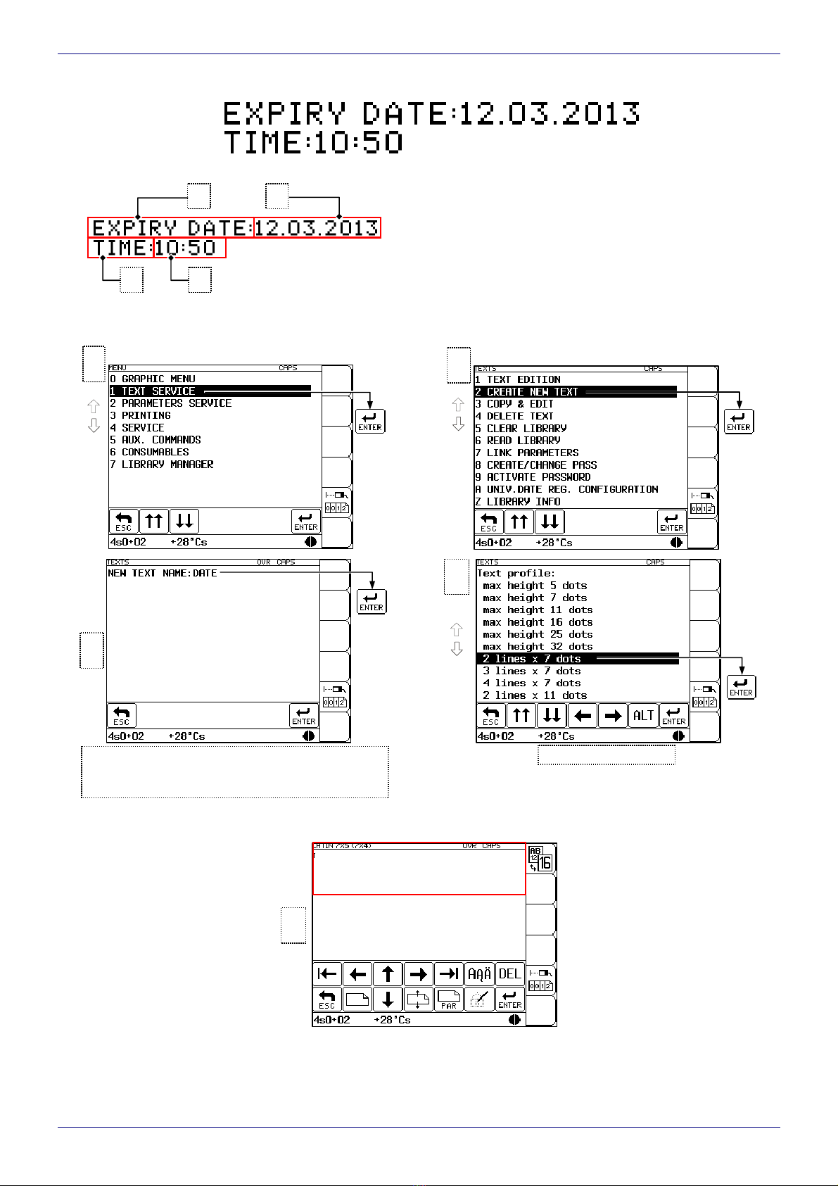
4.4. Opening and Editing a New File ................................................................................................. 9
4.5. Setting Print Parameters........................................................................................................... 12
4.6. Printing...................................................................................................................................... 13
4.6.1. Starting Printing.....................................................................................................................................13
4.6.2. Viewing a File to be Printed on the Terminal Display ...........................................................................14
4.6.3. Stopping Printing...................................................................................................................................15
4.7. Switching the Printer Off ........................................................................................................... 15
5. Routine Maintenance..................................................................................................................16
5.1. Replacing Ink/Solvent Bottle ..................................................................................................... 16
5.2. Replacing iModule®................................................................................................................... 17
5.3. Head Maintenance.................................................................................................................... 19
5.3.1. Removing Head Cover..........................................................................................................................19
5.3.2. Removing Dirt from Print Head .............................................................................................................20
Dear User,
This edition of the document includes most of the changes introduced to the EBS printers
with software version up to 32_0A and the descriptions contained therein correspond to
the printers that are equipped with this software version.
The product delivered to you corresponds to your specific order, and it may happen that
the options and functionality of your printing system differ from some descriptions or illus-
trations. As we need to keep pace with new technological advancement and wish to meet
individual requirements of our clients, we reserve the right to introduce changes in
the design and construction as and when necessary. Therefore, claims cannot be made re-
garding differences to data, illustrations or descriptions contained in this manual. Should
your printer be equipped with options or software that are not illustrated or described in this
manual or should you have additional queries after having read the manual, please contact
any EBS Ink Jet Systeme representative office for more information.
The manufacturer shall not be liable for any damages to the printer resulting from failure to
follow the instructions or from consequences of editorial or publishing errors contained in
this manual.
The application and use of the products are beyond our control and are the full responsibil-
ity of the user.

EBS Ink Jet Systeme GmbH D-51588 Nümbrecht, Germany, Alte Ziegelei 19-25 ++49 (0)2293/939-0 ++49 (0)2293/939-3 e-mail: mail@ebs-inkjet.de
20 20140417#2.2 edited on 2014.04.17 3
1. General Information
The BOLTMARK®series consists of the following INK-JET printer models:
EBS-6500 - the low investment printer for common applications.
EBS-6800 - the all-round model printer with full printing options.
EBS-7200 - the new standard in high-speed marking solutions.
The table below shows a comparison of the primary parameters of the BOLTMARK®-series models men-
tioned above.
Tab. 1.1 EBS-6500 EBS-6800 EBS-7200
MINI / 16 dots
MIDI / 25 dots
Maximum height of
vertical row (Hmax) MAXI / 32 dots
One 5x5 line
Two 5x5 lines
Three 5x5 lines
Four 5x5 lines
Five 5x5 lines
One 7x5 line
Two 7x5 lines
Three 7x5 lines
Four 7x5 lines
One 9x5 line
Two 9x5 lines
Three 9x5 lines
One 11x7 line
Two 11x7 lines
One 14x9 line
Two 14x9 lines
One 16x10 line
One 21x15 line
One 25x15 line
Examples of matrices
(The matrices listed are
available for
the EBS-6500 MIDI
printers as well as
EBS-6800
and EBS-7200 MAXI
printers)
One 32x18 line
1D codes
Bar codes available 2D code (Data Matrix)
to run over 4000 hours (18 months)
to run over 6000 hours (18 months)
Type of iModule®
to run over 8000 hours (18 months)
Print height [mm] 1.4 - 12 1.4 - 12 1.2 - 9
Distance between the head and product [mm] 0 - 30 0 - 30 0 - 15
The symbols used in the above given table have the following meanings:
- YES (available) - NO (unavailable) - available as an option
- YES (available as standard but with limitations)
The complete information on the printer’s features; installation, configuration and operation is contained in
The
BOLTMARK
®
-series Printer User’s Manual. This document contains only the basic information on how to
start and stop the BOLTMARK®-series printer, enter a text to be printed, print the text, exchange a (solvent or
ink) bottle, replace iModule®as and when necessary, and keep the head clean.

EBS Ink Jet Systeme GmbH D-51588 Nümbrecht, Germany, Alte Ziegelei 19-25 ++49 (0)2293/939-0 ++49 (0)2293/939-3 e-mail: mail@ebs-inkjet.de
20 20140417#2.2 edited on 2014.04.17 4
2. Printer Elements
The major components of the BOLTMARK®-series printer are shown in Fig. 2.1.
Fig. 2.1
In addition, the printing system may contain many other sub-assemblies such as a shaft-encoder, assembly
stands, an additional external signaling device and many others. For more details refer to section Installation of
the Printer in The
BOLTMARK
®
-series Printer User’s Manual.
3. Safety Requirements
NOTE:
The printer should be operated by trained staff. It is recommended that operation of the device is supervised.
Place a fire extinguisher suitable for both electrical and chemical fires in the vicinity of the printer.
Do not print in areas where there is a risk of explosion.
Do not print on objects whose temperature exceeds 100C at the time of printing.
Do not use open fire or spark-generating devices in the area where the printer works.
Plug in the printer to the mains socket that is wired to earth.
Adjustments to the electrical part of the system and he head should be performed when power supply is
disconnected.
Do not point the head outlet to persons or animals during printing.
- bottle of solvent (white stopper)
- bottle of ink (black stopper)
- master switch
- print head
- operation panel
- photo-detector
- iModule®

EBS Ink Jet Systeme GmbH D-51588 Nümbrecht, Germany, Alte Ziegelei 19-25 ++49 (0)2293/939-0 ++49 (0)2293/939-3 e-mail: mail@ebs-inkjet.de
20 20140417#2.2 edited on 2014.04.17 5
Wear protective clothes while performing operations to the ink system.
Air contaminated with solvent should be removed to the outside of the building via an unobstructed duct.
Do not use plastic vessels for washing because of the risk of static electricity. Metal vessels are recommended.
Do not leave ink, solvent or wash-up in open vessels.
Before you approach highly flammable liquids remove static electricity by touching an earthed, metal object
(e.g. the earthed printer housing).
Only EBS-approved agents may operate the printer otherwise guarantee claims are not valid!!
In the case of accident...
When ink or solvent spills occur, the spilled fluid should be wiped with a piece of absorbent material and then
removed in compliance with fire and health and safety at work (HSE) regulations.
If the clothing has been splashed, remove it as soon as possible.
Should the eyes or skin get irritated:
EYES need to be rinsed with running water for at least 15 minutes, then you should see an eye specialist,
SKIN needs to be washed with water and soap.
4. Operating the Printer
Before starting the printing system ensure that the appropriate operating conditions are satisfied, paying special
attention to the following:
power supply: 100 - 240V, 50/60Hz (AC),
free access to the printer, upright position of the printer on a table or EBS rack, suitable position of
the photo-detector and print head to ensure that objects are labeled properly.
4.1. Switching the Printer On
Every BOLTMARK®-series printer is equipped with a power supply with a stand-by circuit. There are two
different power switches. One main switch for standby and one switch for turning the printer on.
The double-pole master switch (see Fig. 2.1), which separates two power wires electrically from
the mains; it is located on the right-hand side of the printer next to the mains cord. After the master switch
has been turned on, the printer triggers to the stand-by mode - the red LED on the operation panel (see Fig. 2.1)
between the
ON
and
OFF
keys comes on.
If all the connections are made properly (and the master switch is switched on), just press the
ON
button on
the operation panel.This will initiate the printer starting procedure. While the procedure is being followed, the green
LED above the
INK
ON
/
OFF
key on the operation panel flashes, indicating the start of the ink flow to the head.
The procedure is finished when the yellow READY LED on the operation panel starts glowing. This means that
the head is ready for printing. A detailed description of the starting procedure is contained in
The
BOLTMARK
®
-series Printer User’s Manual.
NOTE:
While the printer start-up procedure is being followed, the iModule®transport valve must be open. An attempt to
start the printer while the transport valve is closed causes the following message to be displayed:
VACUUM DOESN'T INCREASE,
Check iModule
transport protection. If that happens, you should clear the alarm with the
CLEAR
A
LARM
key, open the iModule®trans-
port valve and start the procedure for initiating the flow of ink in the head (with the INK ON command in
the SERVICE menu).

EBS Ink Jet Systeme GmbH D-51588 Nümbrecht, Germany, Alte Ziegelei 19-25 ++49 (0)2293/939-0 ++49 (0)2293/939-3 e-mail: mail@ebs-inkjet.de
20 20140417#2.2 edited on 2014.04.17 6
4.2. Operation Panel
The operation panel enables the printer
operator to control and monitor printer opera-
tion, and start specific procedures as
and when necessary. It is also used for per-
forming such basic operations as turning
the print mode on or off, locating faults,
clearing alarms, etc. For more details refer to
chapter: Operating the Printer in
The
BOLTMARK
®
-series Printer User’s
Manual.
Fig. 4.2.1
4.3. Control MENU
4.3.1. Choosing the Type of Menu
The printer can be operated via a text menu or a graphic menu, according to the user's preferences. Irrespec-
tive of the menu chosen, commands are executed in the same way and both keypad and touch panel can be used
to operate the printer. In the text menu, all commands are available, including service commands to which access
is secured with a password. The graphic menu offers access only to selected commands which are indispensable
for operating the printer. These are shown as icons.
When the printer is started for the first time, the graphic menu is displayed. In order to move to the text menu
choose the icon in the function icon window or the corresponding function key
F6
(which is indispensable
especially when the touch panel is not calibrated). When the text menu is chosen, it remains active each time
the printer is started.
In order to move back to the graphic menu, choose the GRAPHIC MENU item at the highest level of the text
menu.
4.3.2. Graphic Menu
If the printer is operated via the graphic menu, the screen is divided into five sections called windows.
Fig. 4.3.2.1
printer status windowtab window
information window
function icon
window
operating window
LCD color adjustment keys
LCD touch screen
function keys
alphanumerical keypad main pad

EBS Ink Jet Systeme GmbH D-51588 Nümbrecht, Germany, Alte Ziegelei 19-25 ++49 (0)2293/939-0 ++49 (0)2293/939-3 e-mail: mail@ebs-inkjet.de
20 20140417#2.2 edited on 2014.04.17 7
The windows are designed for the following:
Tab window - the icons of the graphic menu are grouped thematically and each group is marked with a tab.
The tab window is designed for easy tab selection. Each tab selected gives access to the corresponding oper-
ating window.
Operating window – contains the icons designed for operating the printer via touch panel. The icons of one
thematic group are displayed at a given moment. Changing the group can be done by selecting a different tab
in the tab window.
Information window – this window shows the name of a text menu function. The icon selected is displayed as
a negative image, and the function name (in the user-selected language) appears in the information window. In
order to execute the function, the selection should be confirmed with the icon on the tab bar. Such
a navigation arrangement helps protect against accidental execution of a dangerous operation.
Printer status window - contains information about the head status in various operating modes (pfor printing,
sfor stop, cstands for removed head cover, vfor special service mode), the ToF setting (i.e. the time over
which an ink drop flies through the head), which describes the physical properties of the ink drop, quality of
phasing and also a graphical indicator of how long the iModule®can still be in use - a more detailed description
is given in section 5.2 Replacing iModule®.
Function icon window - contains a set of function icons, which at the same time, describe the function keys
located on the operator's panel.
The graphic menu icons are grouped in the following way:
Tab 1:
Printing handling functions (successively):
START PRINT,
STOP PRINTING,
EDIT & PRINT CURRENT TEXT,
PRINTING PARAMETERS,
SAVE CURRENT PARAM.,
DISPLAY PRINTED TEXT,
SHIFT COUNTER,
SET SHIFT COUNTER,
GLOBAL COUNTER.
Tab 2:
Text file handling functions (successively):
CREATE NEW TEXT,
TEXT EDITION,
COPY & EDIT,
LINK PARAMETERS,
CREATE/CHANGE PASS,
ACTIVATE PASSWORD,
UNIV.DATE REG. CONFIGURATION,
READ LIBRARY,
DELETE TEXT.
Tab 3:
Service functions (successively):
SERVICE,
iMODULE REPLACEMENT,
CIRCULATE INK,
CLEAN NOZZLE,
FAST OFF,
INK ON,
not used,
not used,
INK SYSTEM SERVICE.

EBS Ink Jet Systeme GmbH D-51588 Nümbrecht, Germany, Alte Ziegelei 19-25 ++49 (0)2293/939-0 ++49 (0)2293/939-3 e-mail: mail@ebs-inkjet.de
20 20140417#2.2 edited on 2014.04.17 8
Tab 4:
Ink Monitoring System handling functions (successively):
OPERATING TIME – applies to bottles,
OPERATING TIME – applies to iModule®,
No. OF TXT/1l,
UNLOCK PROTECTION,
TIME AND DATE,
LIBRARY INFO,
LANGUAGE,
REMOVE PROTECT TIME,
LIBRARY MANAGER.
Tab 5:
The other functions (successively):
ACTIVITY TIME,
HV VALUE,PHOTO,SHAFT state,
CONVEYOR MEASUREMENTS,
SET INK STREAM,
ADJUSTMENTS,
OPTIONS,
READ ERRORS REPORT,
not used,
CLEAR MEMORY.
4.3.3. Text Menu
If the text menu is used, the screen is divided into five areas called windows - as is the case with the graphic
menu.
Fig. 4.3.3.1
The windows are designed for the following:
Terminal status window – contains information on the current terminal settings; for example, it indicates
the graphic cursor co-ordinates (while editing graphics), whether the ©key (to switch between block/small
letters) or the Yor «button is pressed or not, which character input mode (INSert or OveRwrite) is
used, etc.
Operating window – is the main window of the display which shows the service MENU, parameters and mes-
sages, for editing text files, etc.
Navigation icon window - contains a set of keys to facilitate your movement along the MENU tree and for
modification of the parameter settings.
Printer status window - contains information about the head status in the printer’s various operating modes
(pfor print, sfor stop, cstands for removed head cover, vfor service mode), the ToF setting (i.e. the time over
which an ink drop flies through the head), which describes the physical properties of the ink drop, quality of
phasing and also a graphical indicator of how long the iModule®can still be in use - a more detailed description
is given in section 5.2 Replacing iModule®.
Function icon window – contains a set of function icons, which at the same time, describe the function keys
located on the operator's panel.
The text menu has a multi-level tree structure. Commands are executed directly at the lowest level. No action is
initiated by moving from one menu branch to another. Only the execution of a command initiates an action such as
starting the printing, moving to a word processor, changing parameters, etc.
terminal status window operating window
„hot keys” function icon
window
navigation icon window printer status window

EBS Ink Jet Systeme GmbH D-51588 Nümbrecht, Germany, Alte Ziegelei 19-25 ++49 (0)2293/939-0 ++49 (0)2293/939-3 e-mail: mail@ebs-inkjet.de
20 20140417#2.2 edited on 2014.04.17 9
The first character (a digit or a letter) of every MENU item corresponds to the so called hot key
(see Fig. 4.3.3.1). When this key is pressed on the keypad, the cursor bar is positioned on the required item.
The following keys (on the alphanumerical keypad or the LCD touch screen icons) are used to move within
the MENU tree:
Keys/Icons Function
To move the cursor one menu item upwards.
To move the cursor one menu item downwards.
Y(Y) To move the cursor to the first item.
Y(Y) To move the cursor to the last item.
To move the cursor one menu screen upwards (PAGE UP).
To move the cursor one menu screen downwards (PAGE DOWN).
Vor
To move one level downwards (to the next MENU branch) or to confirm the selected
command for execution.
Uor To move one level upwards or cancel the selected command. If you press the icon
several times, you are always moved back to the main MENU level.
NOTE:
After a command has been confirmed with the icon, you may not be able to cancel it. Some commands
are executed immediately.
4.4. Opening and Editing a New File
Both simple and more complex texts can be printed with EBS printers. They can contain; time markers,
the date, expiry dates (via the so-called variable fields). Barcodes (also 2D1Data Matrix codes) and graphics (ei-
ther built-in or created by the user with a graphics processor) can be printed. In addition, so-called text profiles
have been introduced in order to simplify the editing of a text, the adjustment of a text to a required configuration
and also the optimization of print quality and speed. For more details refer to The
BOLTMARK
®
-series Printer
User’s Manual.
Example of how to input a text containing an expiry date and the actual time)
NOTE:
The expiry date and time, which are shown on the illustrations in the following example depend on
the actual settings for date and time in the printer.
Every aspect of the printer operation procedure is described in the following example.
The profile chosen for the below given (2 lines x 7 dots) text is the optimal profile in that case, but the text
can also be created based on general application profiles (for more details refer to
The
BOLTMARK
®
-series Printer User’s Manual).
1Only in the EBS-6800 and EBS-7200 printers, as standard (see Tab. 1.1).

EBS Ink Jet Systeme GmbH D-51588 Nümbrecht, Germany, Alte Ziegelei 19-25 ++49 (0)2293/939-0 ++49 (0)2293/939-3 e-mail: mail@ebs-inkjet.de
20 20140417#2.2 edited on 2014.04.17 10
The following text should be printed:
The text file consists of four subfiles:
Two of them (and in the figure on the left) are
regular Text type subfiles, while the other two (
and in the figure on the left) are also Text type sub-
files but their contents are updated automatically via
variable fields. Subfile contains the expiry date (which
is formed by adding a specific offset to the current date –
the Date+offs. variable field), while subfile contains
the current time (the Time variable field). The entire text
will be printed in Latin 7x5 (every character will be 7 dots
high and 5 dots wide).
Word processor – new
window (contains 1 space)
5
4
Choose a text profile
3
Type in the text name (up to 8 characters - block
or small letters, digits characters excluding . , / \
; : * ? ” < > | [ ] { } = +), e.g. DATE.
2Text service menuMain menu
1

EBS Ink Jet Systeme GmbH D-51588 Nümbrecht, Germany, Alte Ziegelei 19-25 ++49 (0)2293/939-0 ++49 (0)2293/939-3 e-mail: mail@ebs-inkjet.de
20 20140417#2.2 edited on 2014.04.17 11
The above example contains only some of the options that can be used to edit text files. Other useful functions
are:
Keys/Icons Function
F1
or
The information on the current profile of the text being processed and
the possibility of changing the profile as well.
Y( ) or ( )To move the cursor to the first or to the last character in an ASCII subfile.
Y( ) or ( )To move the entire subfile by one pixel (dot) upwards or downwards (or
move the subfile to the previous/following line).
¥To switch between two character insertion modes: INSert/OveRwrite.
¦or To delete a character at the cursor position in a subfile.
«¦To delete the entire subfile.
Graphic editor (available only when Type = Graphic).
¨or National characters.
Edition of subtext
§( ) - set parameters for subtext
as for subtext .
12
«
or
Create subtext on
the right of subtext
14
Edition of subtext
§( ) - set parameters for subtext as
for subtext except for:
Spec. reg. :Time
15 NOTE:
If subtexts use variable fields (subtexts and ), the letters
(in the case of date) and digits (in the case of time) will be
replaced with values during printing (e.g. DA will be replaced
with units of the day of month, MO with dozens and units of
the month of year, whereas YE with units of the year).
13
16
- acknowledge that you have finished editing the text (the text file will be saved).
17
§( ) - set parameters for subtext :
Type : Text
Char. set : Latin 7x5
Typeface :Normal
Chr. width :Proportional
Distance :2
Rotation :None
Spec. reg. :None
Front dist :0
Back dist :0
Edition of subtext
6
7 «
or
Edition of subtext
Create subtext on the right
of the previous one
8
§( ) - set parameters for subtext as
for subtext except for:
Spec. reg. :Date+offs.
9
10
«
or
11
Create subtext below
the previous ones

EBS Ink Jet Systeme GmbH D-51588 Nümbrecht, Germany, Alte Ziegelei 19-25 ++49 (0)2293/939-0 ++49 (0)2293/939-3 e-mail: mail@ebs-inkjet.de
20 20140417#2.2 edited on 2014.04.17 12
Keys/Icons Function
«Q
To switch between alternative display modes for spaces. Spaces can be
displayed as (by default) or as blanks. Spaces are always printed as
blanks no matter which display mode is active.
4.5. Setting Print Parameters
Before the text prepared in section 4.4 is printed, all the required print parameters need to be set. The parame-
ters determine the print rate, the location of the print on objects to be labeled, the direction in which the object
moves in front of the print head, the date offset (to set expiry date), etc.
Set the print parameters in the following way:
Active text : DATE Name of active text.
Linked param. : Name of parameter block linked to the active text.
Height (pix) : 16 Height of the active text, given as a number of dots.
Height : LARGE Print height.
Speed : SLOW Maximum print speed.
Generator : GEN/SHAFT The source of timing signals: the internal generator or shaft-encoder.
Resol. dot/cm : 20 Character resolution (recommended for a given combination of
the Height, Speed and Height (pix) parameters).
Cnv spd m/min : 10.0 The speed at which an object moves in front of the print head if
the internal generator is used for timing (Generator = GEN).
Enc const p/m : 10000 The number of pulses generated by the shaft-encoder over
the distance of 1 meter. Print rate must suit the conveyor travel speed
(Generator = SHAFT).
Vert. direct. : STANDARD Printing in the vertical direction. Prints can be made normally or upside
down.
Space : 2.0 mm The distance from the point where the photo-detector has been acti-
vated to the point where printing of a text file starts.
Text rpt. : 1 Number of printing text repetitions.
Rpt.dist. : 30.0 mm The distance between the beginnings of texts (if Text rpt. > 1).
Conv. direct. : LEFT The direction (left or right) conveyor moves in front of the print head.
Offset : 100 An offset (number of days) from the current date to the expiry date.
Offset2 : 1 An offset (number of days) from the current date to the expiry date.
Counter delta : 1 Incremental/decremental counter increment/decrement. The parameter
is used by the Up counter and Down count. variable fields.
Row repetit. : 1 The number specifying how many times every vertical row will be
printed.
Mode : NORMAL Selection of max print speed mode. The parameter can only be modi-
fied after the service password has been given.
You can choose a parameter to be modified by means of the touch panel (the screen can be scrolled with
the , icons) or the keys. Parameter settings are changed with the icons or by typing in
a setting via the keyboard (this applies to numerical parameters) and confirming with the icon. For
the Active text parameter You can also choose the text file from the library using the icon.
2Printing menu
Main menu
1

EBS Ink Jet Systeme GmbH D-51588 Nümbrecht, Germany, Alte Ziegelei 19-25 ++49 (0)2293/939-0 ++49 (0)2293/939-3 e-mail: mail@ebs-inkjet.de
20 20140417#2.2 edited on 2014.04.17 13
In the example referred to above, only the Offset parameter needs modifying. The default settings can
be used for the other parameters.
Soon after the editing of printing parameters has been finished (acknowledged with the icon)
the parameters can be saved together as a block. The assigned name of the parameter block is the same as
the name of the active text file.
NOTE:
Not all combinations of the Height and Speed parameters and the matrix height given as a number of dots
(the Height (pix) printing parameter) are available. Should an unavailable combination be chosen,
a fragment of the following message is displayed in the printer status window:
Increase PRINT.PARAM. Height or
decrease PRINT.PARAM. Speed or
decrease text height [dots].. In order to get the entire message displayed press the icon.
If the Generator parameter is set to GEN, the printer will make prints regardless of whether an object
moves in front of the print head or not. If the object remains still, the text will be jetted onto one place giving
a vertical line only. While testing the printer where an internal generator is used for timing,it is advisable to
set the Text rpt. parameter to a higher value.
If the Generator parameter is set to SHAFT, the head will make prints only when a shaft-encoder is con-
nected and its axle rotates (for more details on this optional device refer to section Adjusting the Print Rate
in The
BOLTMARK
®
-series Printer User’s Manual). If this is the case, there may be the need (espe-
cially during trials) to complete printing the current text by turning the shaft-encoder axle manually.
4.6. Printing
4.6.1. Starting Printing
Printing can be initiated in two parallel,independent ways:
With the START PRINT command selected on the terminal (description on the figures below).
With the
PRINT
ON / OFF
key on the operation-panel function pad. When the key is pressed, the active text is printed.
The key can be used no matter where the cursor is positioned within the control menu (for example, you can
start printing while editing a text file).
In order to print the text file called DATE prepared in the example in section 4.4 follow the step given below:
NOTE:
Printing can be initiated only and exclusively when the head cover is installed. An attempt to start printing when
no cover is installed causes the Head cover removed message to be displayed and makes printing impossible.
Printing menu
2
Main menu
1

EBS Ink Jet Systeme GmbH D-51588 Nümbrecht, Germany, Alte Ziegelei 19-25 ++49 (0)2293/939-0 ++49 (0)2293/939-3 e-mail: mail@ebs-inkjet.de
20 20140417#2.2 edited on 2014.04.17 14
4.6.2. Viewing a File to be Printed on the Terminal Display
Press or to
return to menu
3
2Printing menuMain menu
1
Type in the text file name (up to
8 characters - block, small letters,
digits and characters excluding .,/\: ;
*?”<>|[ ] { } = +), e.g. DATE.
Press if you wish to select
a text file from the library.
or
Text library
Printing menu
p– print Overprint height
Return to the printing menu - the printing status
is indicated in the head status window.
3
with the
F4
key you can get the name of the text being printed
displayed in the printer status window (over 1 second) during printing

EBS Ink Jet Systeme GmbH D-51588 Nümbrecht, Germany, Alte Ziegelei 19-25 ++49 (0)2293/939-0 ++49 (0)2293/939-3 e-mail: mail@ebs-inkjet.de
20 20140417#2.2 edited on 2014.04.17 15
4.6.3. Stopping Printing
Printing can be terminated in three ways:
With the STOP PRINTING command.
With the QUICK STOP command.
With the
PRINT
ON / OFF
key on the operation-panel function pad (when the key is pressed, the QUICK STOP command
is executed). This key can be used no matter where the cursor is positioned within the control menu (for exam-
ple, you can stop the printing while editing a sub file).
4.7. Switching the Printer Off
There are several modes of switching the printer off:
regular mode (to switch the printer off for a period of up to 1 week),
emergency mode (for no longer than a 1-hour period),
service mode (for no longer than a 1-hour period),
switching off in the regular mode with additional rinsing of valve V3 – a precise description is given in
The
BOLTMARK
®
-series Printer User’s Manual.
Switching the printer off in the regular mode - press the
OFF
key on the operation panel and wait a few
minutes for the printer to turn off. Then the LED between the
ON
and
OFF
keys changes color from green to red.
The SWITCHING THE PRINTER OFF ..... message is displayed on the terminal and the time remaining until
the end of the switching off procedure is displayed in the status window. Also the green LED above the
INK
ON
/
OFF
key on
the operation panel flashes indicating that the flow of ink to and in the head is being stopped.
Switching the printer off in the emergency mode - press the
OFF
key and while holding it down press
and release the
CLEAR
ALARM
key. Or alternatively, you can cut off the supply of electricity to the printer with
the master switch (see Fig. 2.1). This type of switching off is allowed only in the event of an evident
printer failure, especially when the failure to switch the printer off in the regular mode may cause more
extensive or additional damage (such as an ink spill).
Switching the printer off in the service mode - follow the same procedure as for the emergency mode.
The service mode is used to switch the printer off quickly (without rinsing) for a few minutes in order to perform
The printing of
the current text
file is interrupted
2Printing menu
1 Main menu
The current
text file is
printed to
the end
and the printi
ng is stopped.
2Printing menu
1 Main menu

EBS Ink Jet Systeme GmbH D-51588 Nümbrecht, Germany, Alte Ziegelei 19-25 ++49 (0)2293/939-0 ++49 (0)2293/939-3 e-mail: mail@ebs-inkjet.de
20 20140417#2.2 edited on 2014.04.17 16
a service operation. If the unit needs to be switched on and off frequently, then the service mode should only be
used in order to prevent ink from getting diluted excessively.
NOTE:
After the unit has been switched off in the emergency or service modes, wash the inner part of the head (espe-
cially around the gutter) with solvent.
5. Routine Maintenance
Fig. 5.1
5.1. Replacing Ink/Solvent Bottle
The empty bottle condition is normally indicated with a sound alarm and the following terminal message:
SOLVENT LACK or INK LACK
This is the right time to replace the empty bottle with a full one.
This procedure can be performed during printing within 20 minutes after the above message has been dis-
played (If the indicated period of time elapses, printing will be stopped). It involves the following steps:
1. Lift the latch for bottles (see Fig. 5.1) and remove the empty bottle from which ink (or solvent) has been taken
so far; the following message can appear on the terminal:
SOLVENT:
NO BOTTLE or INK:
NO BOTTLE
2. Lift the latch again, put a new bottle in place of the removed one, following the information given on the latch
(insert an ink bottle equipped with a black stopper to the black connection on the right, i.e. a solvent bottle
equipped with a white stopper to the white connection on the left - see Fig. 2.1) and press it as much as practi-
cally possible making sure that the latch is in the appropriate bottle groove. One or more messages can be dis-
played. If the bottle is right, i.e. a new one (or in other words, not accepted yet), the following message should
appear at first:
CODE VERIFYING:
WAIT 10 SECONDS PLEASE
3. If the BOTTLE ACCEPTED message is displayed within 10 seconds, this means that the bottle can be used in
a given printer.
latch for bottles
solvent
ink
iModule
®
iModule
®
slideways
iModule
®
latches

EBS Ink Jet Systeme GmbH D-51588 Nümbrecht, Germany, Alte Ziegelei 19-25 ++49 (0)2293/939-0 ++49 (0)2293/939-3 e-mail: mail@ebs-inkjet.de
20 20140417#2.2 edited on 2014.04.17 17
5.2. Replacing iModule®
iModule®is a basic subassembly of the BOLTMARK®-series printer ink system. It contains component
parts on which the reliability of printer operation and also print quality largely depend. For this reason the iModule®
must be replaced from time to time so that faultless operation of the printer is ensured. Every iModule®is equipped
with a transponder, where the data such as the type of module, its use-by date, the limit of running hours assigned
to it and also its expiry date is saved. This information is available in the CONSUMABLES/
iMODULE INFORMATION menu and also on the iModule®label.
The iModule®should be replaced periodically before the time limit assigned to it expires or before the iModule®
is past its expiry date (both of the settings can be viewed with the OPERATING TIME command in
the CONSUMABLES/ iMODULE INFORMATION menu), otherwise printing is disabled. The level of use of
the iModule®is also presented in the printer status window in graphical format. Such a graphical indication shows
(approximately) the remaining running time of the iModule®or the time to the end of the iModule®expiry date.
The table below shows successive graphical symbols indicating the remaining running times of the iModule®or
the time to the end of the iModule®expiry date, whichever comes sooner. The symbols are shown in a negative
color.
Symbol
Remaining running time or time to
the end of expiry date [%] 100-88 87-76 75-63 62-51 50-38 37-26 25-13 12-1 <1
The approaching date of replacement of the iModule®is indicated with one of the below given messages:
iModule running time
is below 10%
CALL SERVICE PLEASE
iModule running time expires
in less than 300 hours
CALL SERVICE PLEASE
iModule expires within
1 month
CALL SERVICE PLEASE
-if the printer runs over a limited number of hours and the iModule®
expiry date comes before the time limit assigned to the module elapses.
The above-given messages are repeated cyclically (and also each time when the printer is started) until
the time limit assigned to the iModule®elapses (or the expiry date elapses) or until the iModule®is replaced with
a new one. The message displayed is accompanied by an acoustic signal, which can be turned off with the
CLEAR
A
LARM
key.
The iModule®replacement procedure consists of the following steps:
1. Start the printer and wait until it reaches the ready condition (the yellow READY LED starts emitting continuous
light).
2. Choose the iMODULE REPLACEMENT command from the SERVICE/ SERVICE COMMANDS menu.
The following message appears on the display:
iModule replacement procedure.
ARE YOU SURE (Y,N)?
(Y=ENTER, N=ESC)
3. After the ”Y” key or the icon has been pressed as confirmation, the following message is displayed:
Prepare a new iModule.
Make sure that there is minimum
3cm of ink in the bottle
ENTER - continue, ESC - abort
NOTE:
While the iModule®filling procedure is being followed, the level of ink in the bottle must be 3 cm mini-
mum - such an amount of ink is needed to fill the iModule®.
4. Follow the above request and prepare a new iModule®, make sure that there is a sufficient amount of ink in
the bottle, and then confirm your readiness for replacement by pressing the icon. At that moment

EBS Ink Jet Systeme GmbH D-51588 Nümbrecht, Germany, Alte Ziegelei 19-25 ++49 (0)2293/939-0 ++49 (0)2293/939-3 e-mail: mail@ebs-inkjet.de
20 20140417#2.2 edited on 2014.04.17 18
the iModule®replacement procedure starts and it can take up to 20 minutes. The following message is dis-
played:
iModule replacement procedure
in progress.
iModule is under pressure !!
Do not remove iModule.
Wait for relevant message.
At that time the flow of ink in the head is stopped, the ink filtering procedure takes place for a short time and ink
system pressure is reduced (these operations are indicated by the blinking green LED above the
INK
ON
/
OFF
key on
the operation panel). Wait for the following message:
While the printer is running:
- Press transport protection,
- Remove iModule & wait
for next message.
5. Close the transport-safety valve (see Fig. 5.2.2) and then remove iModule®from the printer. In order to pull out
the iModule®from the inside of the ink system chamber you need to tilt two fastening latches aside (see
Fig. 5.1). A few seconds after this operation the following message is displayed:
Insert iModule & wait
for next message.
NOTE:
The connections of the iModule®removed should be secured against potential leaks with spe-
cial plugs supplied together with a new Module®.
6. Install a new iModule®in the printer by pushing the module along the slideways to the limit (when the iModule®
reaches its proper position, the latches make a characteristic sound – a ”click”). When the module is detected
in the printer, the following message is displayed:
A new iModule detected
Operating time hhhh:mm
Expiry date dd.mm.yy
Shelf life dd.mm.yy
C=0
Do you really want to install it?
(Y,N)? and the BOTTOM LED on the inner
panel starts blinking, which means that
the module is empty.
7. After the ”Y” key or the icon has been
pressed as confirmation, the following mes-
sage is displayed:
CODE VERIFYING:
WAIT 10 SECONDS PLEASE
and in a few seconds - another one:
Open transport protection,
and then press ENTER.
Follow the above given request (and that on
the sticker on the iModule®) and open
the transport-safety valve of the iModule®
(see Fig. 5.2.2). When the operation is com-
pleted, confirm it with the icon.
transport
valve
iModule
®
iModule
®
installing direction
Fig. 5.2.1

EBS Ink Jet Systeme GmbH D-51588 Nümbrecht, Germany, Alte Ziegelei 19-25 ++49 (0)2293/939-0 ++49 (0)2293/939-3 e-mail: mail@ebs-inkjet.de
20 20140417#2.2 edited on 2014.04.17 19
Fig. 5.2.2
8. At that moment the procedure for filling the iModule®starts, which is confirmed with the following message:
Filling iModule...
Transport protection
must be open !!
Please wait.
and with the blinking green LED above the
INK
ON
/
OFF
key on the operation panel.
9. When the iModule®filling procedure is finished, ink starts jetting (the green LED above the
INK
ON
/
OFF
key on
the operation panel starts blinking), and when the printer reaches the ready state (the yellow READY LED
emits light continuously), you can start printing.
The ending of the iModule replacement procedure is indicated with the following message:
iModule replaced & accepted
Press ENTER...
and after it has been confirmed, the following message is displayed:
iModule
iModule accepted
Press ENTER...
Additional information about iModule®replacement:
All the time while the iModule® replacement procedure is being followed, the message
iModule replacement in progress is being displayed in the printer status window.
Any removal of the iModule®from the printer is indicated by short acoustic signals.
The replacing of the iModule®should take as little time as possible (a new iModule®should be installed
immediately the previous one has been removed) to prevent printer subassemblies (mainly switching-over
contact pins) from drying up.
After the new iModule®has been filled with ink, the time of ink flight in the head (displayed in the printer status
window) can exceed the permissible range for some time. A short-lived deterioration of print quality can also
occur. If the symptoms do not disappear within 1 to 2 hours, contact your service point.
If an attempt is made to install the iModule®whose use-by date (the Shelf life parameter) is exceeded,
the iModule shelf life expired message is displayed and the module is not accepted. A valid module shall be
used.
If the iModule®replacement procedure is interrupted (e.g. due to a power failure), it will re-continue after re-
start.
If the iModule replacement aborted message is displayed in the printer status window, this means that
the user did not agree to the installation of a new iModule®. In such a case it is impossible to start printing.
The iModule®replacement procedure should be restarted and followed to the end.
5.3. Head Maintenance
5.3.1. Removing Head Cover
Before any operations are performed within the print head, remove the head cover first. Follow the steps given
below for this purpose:
1. Uninstall the print head from the holder with which it is fixed in place.
2. Screw out clamping screw from the head cover – the screw cannot be screwed out completely, it can only
be loosened to its limit.
3. Pull out the print head from its cover carefully .
transport valve
transport valve closed:
in vertical position
and pushed in
transport valve open: in
horizontal position
and protruding

EBS Ink Jet Systeme GmbH D-51588 Nümbrecht, Germany, Alte Ziegelei 19-25 ++49 (0)2293/939-0 ++49 (0)2293/939-3 e-mail: mail@ebs-inkjet.de
20 20140417#2.2 edited on 2014.04.17 20
Fig. 5.3.1.1
NOTE:
Make sure that the clamping screw is screwed home properly when the head cover is being reinstalled as it
is designed to serve not only as mechanical fastening but also as an electrical connection between the cover
and the printer housing.
The print head is equipped with a sensor for detecting any removal of the cover (see Fig. 5.3.1.1). When
the cover is removed, printing is suspended automatically and the printer moves to the cover mode. Printing
cannot be restarted until the cover is re-installed.
5.3.2. Removing Dirt from Print Head
It is recommended that the inside of the head be checked for cleanness periodically, (preferably every day)
during maintenance and then ink deposits, (if present), removed from the electrodes, the nozzle and the gutter with
a solvent spray bottle. A compressed air gun or a soft paint brush can also be used.
Fig. 5.3.2.1
print head
spray
waste solvent metal vessel
clamping screw
head cover
head open sensor
This manual suits for next models
2
Table of contents
Other EBS Printer manuals

EBS
EBS EBS 2600 User manual

EBS
EBS EBS-260 User manual

EBS
EBS EBS 2600 User manual

EBS
EBS HandJet 250 User manual

EBS
EBS EBS-1500 SERIES Installation guide

EBS
EBS HANDJET -260 User manual

EBS
EBS 6600 Technical specifications

EBS
EBS HANDJET -260 User manual

EBS
EBS 2500 Instruction sheet

EBS
EBS EBS-6100 User manual