Ecco 5135 Series User manual

920-5135-00 Rev. D Page 1 of 4
Do not install and/or operate this safety product unless you have read and understand the
safety information contained in this manual.
1. Proper installation combined with operator training in the use, care, and maintenance of emergency warning devices are
essential to ensure the safety of you and those you are seeking to protect.
2. Exercise caution when working with live electrical connections.
3. This product must be properly grounded. Inadequate grounding and/or shorting of electrical connections can cause high
current arcing, which can cause personal injury and/or severe vehicle damage, including re.
4. Proper placement and installation are vital to the performance of this warning device. Install this product so that output
performance of the system is maximized and the controls are placed within convenient reach of the operator so that s/he
can operate the system without losing eye contact with the roadway.
5. It is the responsibility of the vehicle operator to ensure during use that all features of this product work correctly. In use, the
vehicle operator should ensure the projection of the warning signal is not blocked by vehicle components (i.e., open trunks
or compartment doors), people, vehicles, or other obstructions.
6. The use of this or any other warning device does not ensure all drivers can or will observe or react to a warning signal.
Never take the right-of-way for granted. It is your responsibility to be sure you can proceed safely before entering an
intersection, driving against trafc, responding at a high rate of speed, walking on or around trafc lanes.
7. This equipment is intended for use by authorized personnel only. The user is responsible for understanding and obeying
all laws regarding warning signal devices. Therefore, the user should check all applicable city, state, and federal laws and
regulations. The manufacturer assumes no liability for any loss resulting from the use of this warning device.
WARNING!
Failure to install or use this product according to manufacturers recommendations may result in property damage,
serious bodily/personal injury, and/or death to you and those you are seeking to protect!
!
Introduction:
The ECCO 5135 series is a powerful, mid-sized, permanent
or vacuum-magnet mount rotating minibar. The low prole and
ease of installation make it one of the most versatile warning
products on the market today.
Specications:
Size: 15.5” x 8.2” x 5.7”
Weight: Permanent Mount: 3.7 lb.
Vacuum-Magnet Mount: 5.9 lb.
Voltage: Model 5135: 12 VDC systems
Current draw: 10.3 Amps avg. @ 12 VDC
Flashes: 480 ashes/min. nominal
Bulb: 55 Watt, 12 VDC, H1, halogen
Installation and Operation Instructions
Minibar
5135 Series
Permanent and
Vacuum-Magnet Mount
15” Rotating Minibar

920-5135-00 Rev. D Page 2 of 4
Permanent Mounting:
Select the mounting location for the minibar on a at, smooth
surface. If the minibar is to be mounted on a curved surface,
such as on the roof of the vehicle, choose a placement with
the least amount of curvature. The mounting location for the
minibar should be chosen such that there is maximum
visibility to the oncoming trafc.
CAUTION:
When drilling into any vehicle surface, make sure that the
area is free from any electrical wires, fuel lines, vehicle
upholstery,etc., that could be damaged.
!
1. Using the mounting holes of the minibar, mark the loca-
tions for the mounting holes. Drill the mounting holes
using a 7/32” drill.
2. Drill a 3/8” hole for the minibar’s power supply wire.
The hole should be underneath where the minibar will
be mounted. Place the supplied grommet in the hole, to
protect the wires from the sharp edges of the hole.
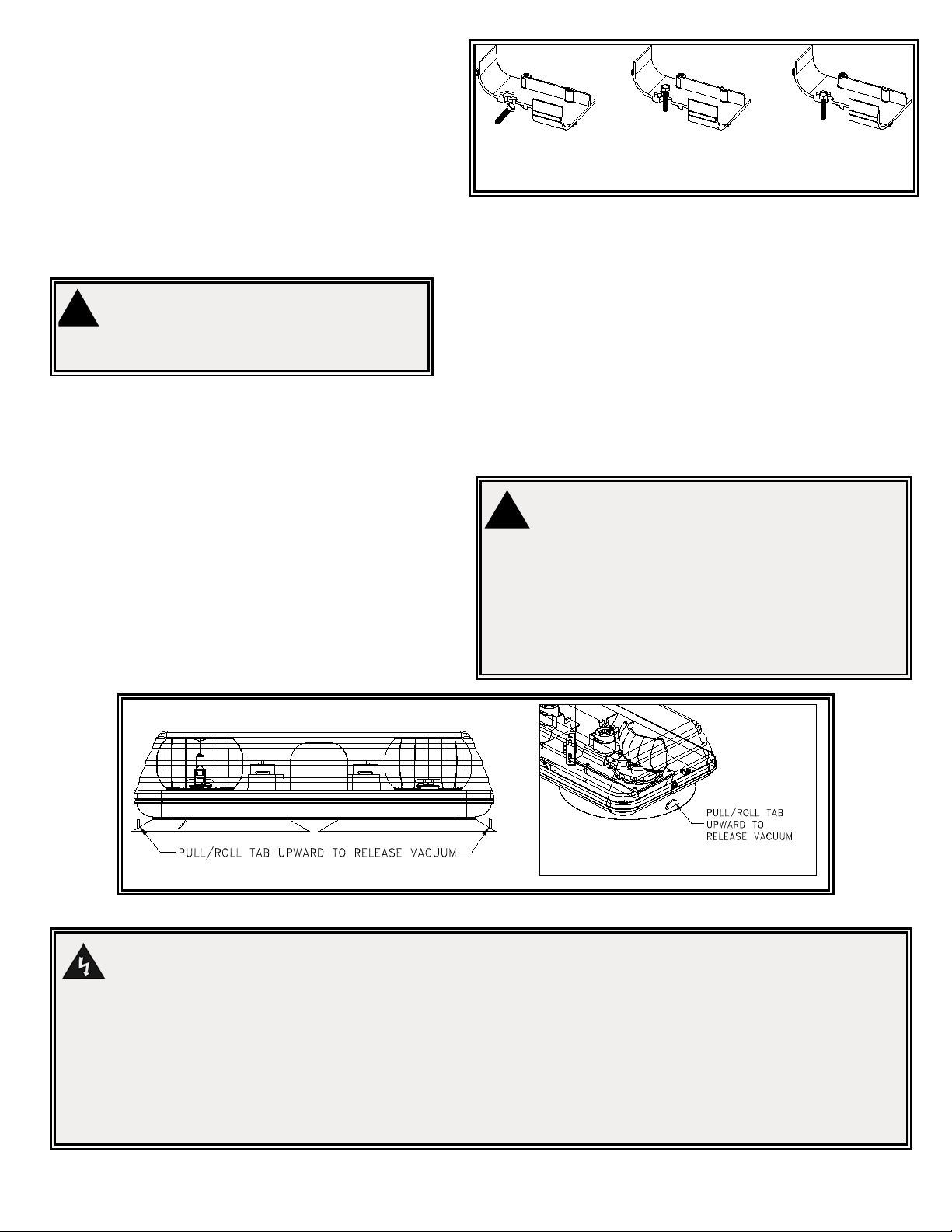
3. Place the four (4) mounting bolts in the bottom of the
base as shown in Figure 1. The base has a mechanism
to hold the bolts in place for installation.
4. Mount the minibar, with the bolts going through the holes
drilled in step 1, routing the wire through the grommet
installed in step 2. See the Wiring section of this manual
for further wiring instructions. Install washers and nuts,
and secure the unit.
INSERT BOLT
THROUGH LARGE
END OF SLOT
PUSH BOLT TO
SMALL END
OF SLOT
PULL BOLT
HEAD DOWN
INTO PLACE
Vacuum-Magnet Mounting:
The vacuum-magnet mount feature includes two (2) suction cups on
the bottom of the minibar, with a magnet inside each of the suction
cups, for a secure, temporary mount. The minibar should be placed
in the center or the roof where the least amount of curvature occurs.
Before installing, make sure there is no debris on the bottom of the
minibar or on the roof of the vehicle, which could reduce the holding
power of the suction cups and magnets. Place and remove the mini-
bar without sliding to avoid scratching the paint on the vehicle. After
placement, the minibar should adhere rmly to the surface. If the unit
slides or moves easily, a proper installation has not been obtained.
To release the vacuum, lift each tab to release the airlock (see Figure
2). To protect the rubber cushion/magnet assembly, return minibar to
the box when not in use. Do not attempt to attach to ice-covered
surface.
Installation & Mounting:
Carefully remove the minibar and place it on a at surface.
Examine the unit for transit damage, broken lamps, etc. If
damage is found, contact the transit company or ECCO. Do
not use damaged or broken parts.
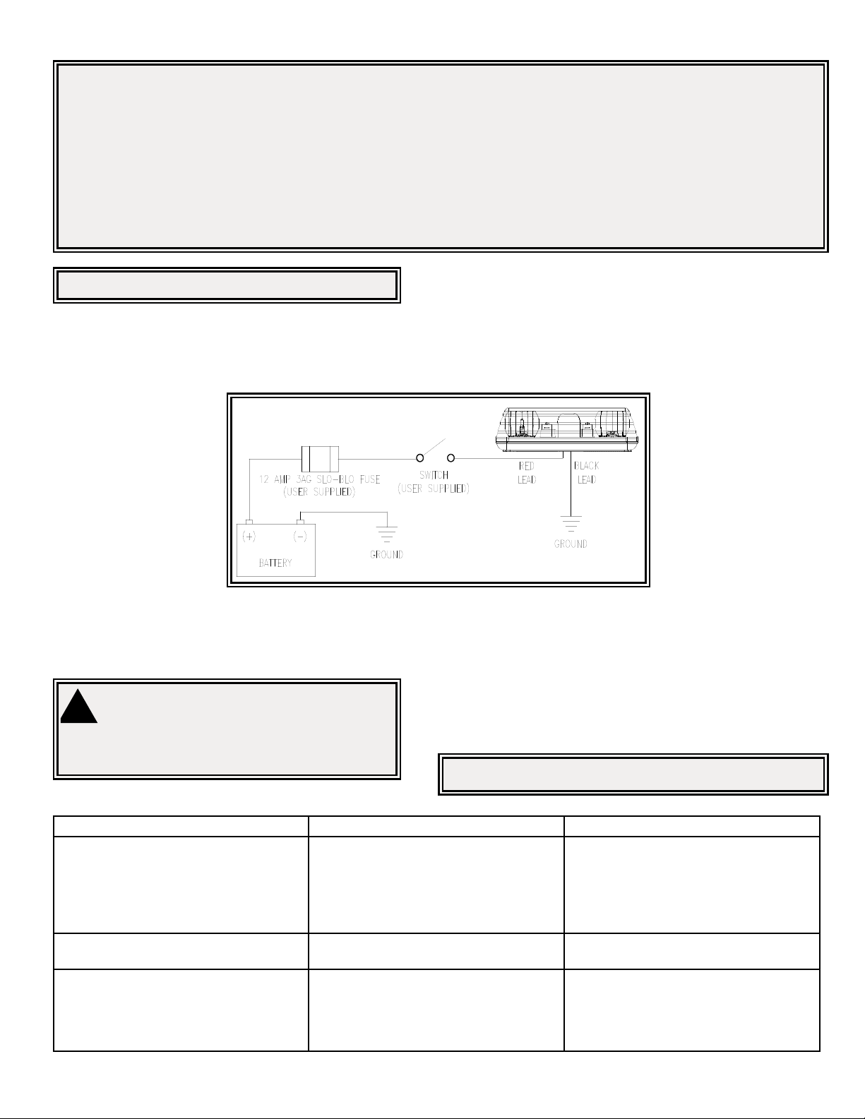
!
WARNING!
Maximum recommended vehicle speed for safe operation using the
Vacuum Mount model is 65 mph (104 km/h), when tted to the center
of a vehicle roof of steel construction. Higher speeds could cause the
mount to fail, resulting in the minibar ying off of the vehicle, which
could cause damage to other vehicles, and injury or death to the pas-
sengers. The vacuum-magnet mount is not intended as a permanent
mounting for the minibar. The vacuum-magnet mount unit must be
mounted on a at smooth magnetic surface (i.e. no berglass, ribbed
style roofs, etc.). Ensure that the magnet is kept clean.
Figure 2
Failure to follow these instructions can result in re or injury from excessive heat build up.
Operator is responsible for ensuring cigarette adapter ts correctly into cigarette/auxiliary outlet used.
For proper operation, verify cigarette/auxiliary outlet circuit is rated to supply, a minimum of 12 amps. (See specications section for rated current in
amperes). Do not exceed the current rating for the cigarette lighter power outlet recommended by vehicle manufacturer.
Keep cigarette lighter adapter, and outlet, clean and free of debris.
Do not use the cigarette lighter adapter when wet.
Insert cigarette lighter adapter fully into the outlet for proper connection.
Grasp cigarette lighter adapter, NOT cord, to remove from outlet.
Remove cigarette lighter adapter completely from outlet when light is not in use.
WARNING!

Page 3 of 4920-5135-00 Rev. D
Wiring Instructions:
Notes:
1. Larger wires and tight connections will provide longer service life for components. For high current wires it is highly recommended that terminal
blocks or soldered connections be used with shrink tubing to protect the connections. Do not use insulation displacement connectors (e.g., 3M
Scotchlock type connectors).
2. Route wiring using grommets and sealant when passing through compartment walls. Minimize the number of splices to reduce voltage drop.
High ambient temperatures (e.g., under-hood) will signicantly reduce the current carrying capacity of wires, fuses, and circuit breakers. All wiring
should conform to the minimum wire size and other recommendations of the manufacturer and be protected from moving parts and hot surfaces.
Looms, grommets, cable ties, and similar installation hardware should be used to anchor and protect all wiring.
3. Fuses or circuit breakers should be located as close to the power takeoff points as possible and properly sized to protect the wiring and devices.
4. Particular attention should be paid to the location and method of making electrical connections and splices to protect these points from corrosion
and loss of conductivity.
5. Ground termination should only be made to substantial chassis components, preferably directly to the vehicle battery.
6. Circuit breakers are very sensitive to high temperatures and will “false trip” when mounted in hot environments or operated close to their capacity.
Important: Disconnect the battery before wiring up the bar.
The 5135 series Blaze2 minibar is designed to operate on a 12
or 24 VDC negative ground system. Use 18 AWG (UL 1015)
or larger wires. If the wire is to be exposed to a high tempera-
ture environment, use 18 AWG (UL 3265 grade min.) type wire.
Connect the black lead to the vehicle chassis, or preferably the
negative terminal of the battery. Bring the red lead to the user supplied
control switch, and then to the battery or to the battery side of the starter
solenoid or alternator. Install a 12 Amp 3AG SLO-BLO fuse to protect the
vehicle’s wiring system against shorts. Note: This safety device must
be connected to a separate, fused power point. Do not wire in paral-
lel with any other accessory. See Figure 3. The belt drive will rotate in
a clockwise direction (when looking down on the unit from above).
Figure 3
Maintenance:
Clean the lens and base with soap and water, or a lens polish us-
ing a soft cloth.
WARNING!
Lamps are extremely hot! Allow to cool completely before
attempting to remove. Gloves and eye protection should be
worn when handling halogen lamps as they are pressurized and
accidental breakage can result in ying glass.
!
Bulb Replacement:
1. Remove the two (2) lens screws at either end of the base, and
remove the lens.
2. Remove and replace the bulb, ECCO P/N R5812BH for 12 volt units,
and R5824BH for 24 volt units. Do Not touch the glass portion of
the bulb. Use clean gloves, replacement bulb bag, nger cots, etc.,
to prevent hand oil from contaminating the bulb, causing failure.
3. Replace the lens.
Problem Probable Cause Suggested Remedy
Unit does not function when turned on Poor ground or power connection
Fuse Blown
No power / improper power
Unit has been damaged
Check connections at the battery and the
unit and repair
Check fuse, replace if necessary
Verify that 12 VDC is reaching unit
Return to ECCO
Rotator does not turn but lamp functions Open circuit in wiring of rotator
Unit has been damaged
Repair wiring
Return to ECCO
Rotator turns but lamp does not function Lamp has burned out
Open circuit in lamp wiring of rotator
Unit has been damaged
Replace lamp
Check for loose connection or damaged
wires between motor and lamp assembly
(2 wires)
Return to ECCO
Trouble Shooting:
Note: Operating the vehicle without the lens installed on this product
will result in damage that will not be covered under warranty.

920-5135-00 Rev. D Page 4 of 4
Replacement Parts/Accessories:
Description Part No.
Replacement Lens, Amber R5100LA
Replacement Belt R5100B
55 Watt Halogen Bulb, 12 VDC (2 bulbs per minibar) R5812BH
Vacuum-Magnet Mount Kit (includes hardware & coil cord) A5300VMK
Magnetic Mount Kit (includes hardware & coil cord) A5300MK
Vibration Dampening Kit A6600VDK
Manufacturer Limited Warranty and Limitation of Liability:
Manufacturer warrants that on the date of purchase this product will conform to Manufacturer’s specications for this product (which are
available from the Manufacturer upon request), and Manufacturer further warrants that this product is free from defects in materials and
workmanship. This Limited Warranty extends for twenty-four (24) months (90 days for bulb) from the date of purchase. Other warranties
may apply, call Manufacturer for details. Manufacturer will, at its discretion, repair or replace any product (other than the bulb) found by the
Manufacturer to be defective and subject to this Limited Warranty.
DAMAGE TO PARTS OR PRODUCTS RESULTING FROM TAMPERING, ACCIDENT, ABUSE, MISUSE, NEGLIGENCE, UNAPPROVED
MODIFICATIONS, FIRE OR OTHER HAZARD; IMPROPER INSTALLATION OR OPERATION; OR NOT BEING MAINTAINED IN ACCOR-
DANCE WITH THE MAINTENANCE PROCEDURES SET FORTH IN MANUFACTURER’S INSTALLATION AND OPERATING INSTRUC-
TIONS VOIDS THIS LIMITED WARRANTY.
ORAL STATEMENTS OR REPRESENTATIONS ABOUT THE PRODUCT WHICH MAY HAVE BEEN MADE BY SALESPEOPLE, DEAL-
ERS, AGENTS OR OTHER MANUFACTURER’S REPRESENTATIVES DO NOT CONSTITUTE WARRANTIES. THIS LIMITED WAR-
RANTY MAY NOT BE AMENDED, MODIFIED, OR ENLARGED EXCEPT BY A WRITTEN AGREEMENT SIGNED BY AN AUTHORIZED
OFFICIAL OF MANUFACTURER WHICH EXPRESSLY REFERS TO THIS LIMITED WARRANTY.
Exclusion of Other Warranties:
MANUFACTURER MAKES NO OTHER WARRANTIES, EXPRESS OR IMPLIED. THE IMPLIED WARRANTIES FOR MERCHANTABIL-
ITY OR FITNESS FOR A PARTICULAR PURPOSE ARE HEREBY EXCLUDED AND SHALL NOT APPLY TO THE PRODUCT. BUYER’S
SOLE AND EXCLUSIVE REMEDY IN CONTRACT, TORT, OR UNDER ANY OTHER THEORY AGAINST MANUFACTURER REGARDING
THE PRODUCT AND ITS USE SHALL BE THE REPLACEMENT OR REPAIR OF THE PRODUCT AS DESCRIBED ABOVE.
Limitation of Liability:
IN THE EVENT OF LIABILITY FOR DAMAGES ARISING OUT OF THIS LIMITED WARRANTY OR ANY OTHER CLAIM RELATED TO
THE MANUFACTURER’S PRODUCTS, MANUFACTURER’S LIABILITY FOR DAMAGES SHALL BE LIMITED TO THE AMOUNT PAID
FOR THE PRODUCT AT THE TIME OF THE ORIGINAL PURCHASE. IN NO EVENT SHALL MANUFACTURER BE LIABLE FOR LOST
PROFITS, THE COST OF SUBSTITUTE EQUIPMENT OR LABOR, PROPERTY DAMAGE, OR OTHER SPECIAL, CONSEQUENTIAL,
OR INCIDENTAL DAMAGES BASED UPON ANY CLAIM FOR BREACH OF CONTRACT, IMPROPER INSTALLATION, NEGLIGENCE,
OR OTHER CLAIM, EVEN IF MANUFACTURER OR A MANUFACTURER’S REPRESENTATIVE HAS BEEN ADVISED OF THE POS-
SIBILITY OF SUCH DAMAGES. MANUFACTURER SHALL HAVE NO FURTHER OBLIGATION OR LIABILITY WITH RESPECT TO THE
PRODUCT OR ITS SALE, OPERATION AND USE, AND MANUFACTURER NEITHER ASSUMES NOR AUTHORIZES THE ASSUMP-
TION OF ANY OTHER OBLIGATION OR LIABILITY IN CONNECTION WITH SUCH PRODUCT.
This Limited Warranty denes specic legal rights. You may have other legal rights which vary from state to state. Some states do not allow
the exclusion or limitation of incidental or consequential damages.
© 2006 ECCO
833 West Diamond St
Boise, Idaho 83705
Customer Service
USA 800.635.5900
UK + (0)113 237 5340
AUS +61 (0)3 63322444
www.eccogroup.com
Other Ecco Safety Equipment manuals
Popular Safety Equipment manuals by other brands

METOLIUS
METOLIUS Equalizer quick start guide

TEUFELBERGER
TEUFELBERGER fImblSAVER Manufacturer's information and instructions for use

AUSTRIALPIN
AUSTRIALPIN Hydra 2.EVO manual

ABS
ABS ABS-Lock X-Flat installation manual

Safety Technology International
Safety Technology International STI-6400 Installation

Janus
Janus E-Series installation guide