Echo 99944200540 User manual

X7532279111
© 02/2020 ECHO Inc.
Operator’s
Manual
99944200540
Trimmer
Attachment
FOR MODELS: SRM-2100SB, 2400SB, 210SB, 211SB, 225SB, 260SB,
261SB, PAS-2100, 2400, 2601, 210, 211, 225, 225VP, 225VPB, 225SB,
230, 231, 260, 261, 265, 266, 280, 2620
The engine exhaust from this product contains chemicals
known to the State of California to cause cancer, birth defects, or
other reproductive harm.
Read and understand all provided literature before use.
Failure to do so could result in serious injury.

TABLE OF CONTENTS 99944200540
2 X7532279111
© 02/2020 ECHO Inc.
TABLE OF CONTENTS
Table of Contents........................................................................................ 2
Introduction ................................................................................................. 3
Servicing Information .................................................................................. 3
Parts/Serial Number............................................................................. 3
Service................................................................................................. 4
ECHO Consumer Product Support...................................................... 4
Product Registration ............................................................................ 4
Additional Literature............................................................................. 4
Safety.......................................................................................................... 4
Manual Safety Symbols and Important Information............................. 4
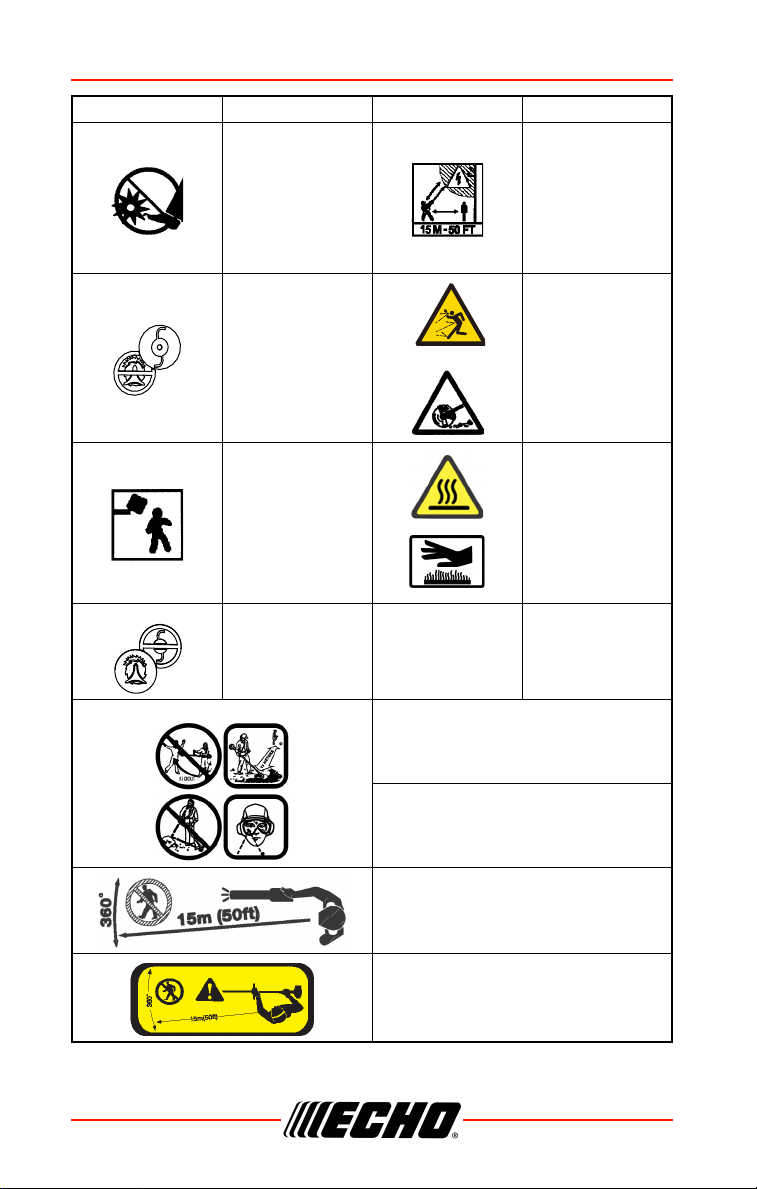
International Symbols .......................................................................... 5
Personal Condition and Safety Equipment .......................................... 7
Equipment.......................................................................................... 12
Description ................................................................................................ 13
Contents.................................................................................................... 14
Assembly................................................................................................... 14
Power Head Shaft to Lower Shaft Assembly..................................... 14
Operation .................................................................................................. 15
Operation With Blades ....................................................................... 15
Blade Selection.................................................................................. 17
Applications ....................................................................................... 18
Operating Techniques - Nylon Line Head:......................................... 18
Operating Techniques - metal or plastic blade .................................. 19
Reaction Forces................................................................................. 20
Blade Cutting Problems ..................................................................... 22
Maintenance ............................................................................................. 22
Skill Levels ......................................................................................... 23
Maintenance Intervals........................................................................ 23
Lubrication ......................................................................................... 24
Nylon Line Replacement.................................................................... 25
Storage ..................................................................................................... 27
Storage Hook Installation................................................................... 27
Specifications............................................................................................ 27
Product Registration.................................................................................. 28
Notes .........................................................................................................30

99944200540 INTRODUCTION
1X7532279111 3
© 02/2020 ECHO Inc.
INTRODUCTION
Specifications, descriptions and illustrative material in this literature are as
accurate as known at the time of publication, but are subject to change
without notice. Illustrations may include optional equipment and
accessories, and may not include all standard equipment.
Read and understand all provided literature.
Literature contains specifications and
information for safety, operation,
maintenance, storage, and assembly
specific to this product. Scan QR codes for
more information.
For additional literature, including safety manuals where applicable, or
questions regarding terms used in this manual, visit:
https://www.echo-usa.com/manuals
OR
https://www.shindaiwa-usa.com/manuals
SERVICING INFORMATION
Parts/Serial Number
Genuine ECHO Parts and
Assemblies for your ECHO products
are available only from an Authorized
ECHO Dealer. When you do need to
buy parts always have the Model
Number and Serial Number of the unit
with you. For future reference write them in the space provided below.
Model No. _______________ Serial No. _______________

SAFETY 99944200540
4 X7532279111
© 02/2020 ECHO Inc.
Service
Service of this product during the warranty period must be performed by an
Authorized ECHO Service Dealer. For the name and address of the
Authorized ECHO Service Dealer nearest you, ask your retailer or call:
1-800-432-ECHO (3246). Dealer information is also available on our Web
Site www.echo-usa.com. When presenting your unit for Warranty service/
repairs, proof of purchase is required.
ECHO Consumer Product Support
If you require assistance or have questions concerning the application,
operation, or maintenance of this product, call the ECHO Consumer
Product Support Department at 1-800-432-ECHO (3246) from 8:00 am to
5:00 pm (Central Standard Time) Monday through Friday. Before calling,
please know the model and serial number of your unit.
Product Registration
Register your ECHO equipment on-line at www.echo-usa.com or by filling
out the product registration sheet included in this manual. Registering your
product confirms warranty coverage and provides a direct link to ECHO if
we find it necessary to contact you.
Additional Literature
In addition to finding information online, information is available from your
Authorized ECHO Service Dealer, or by contacting ECHO Inc., 400
Oakwood Road, Lake Zurich, IL 60047 1-800-432-ECHO (3246).
SAFETY
Manual Safety Symbols and Important Information
Throughout this manual and on the product itself, you will find safety alerts
and helpful, informational messages preceded by symbols or key words.
The following is an explanation of those symbols and key words and what
they mean to you.
The safety alert symbol accompanied by the word “DANGER”
calls attention to an act or condition which WILL lead to serious
personal injury or death if not avoided.

99944200540 SAFETY
1X7532279111 5
© 02/2020 ECHO Inc.
The safety alert symbol accompanied by the word “WARNING”
calls attention to an act or condition which CAN lead to serious
personal injury or death if not avoided.
The safety alert symbol accompanied by the word “CAUTION”
calls attention to an act or condition which might lead to minor
or moderate personal injury if not avoided.
The enclosed message provides information necessary for the
protection of the unit.
Note: This enclosed message provides tips for use, care and
maintenance of the unit.
CIRCLE AND SLASH SYMBOL
This symbol means the specific action shown is prohibited.
Ignoring these prohibitions can result in serious or fatal injury.
International Symbols
Symbol Description Symbol Description
Warning, see
Operator’s
Manual
Safety / Alert
Wear eye, ear
and head
protection
Finger severing
Wear hand and
foot protection
Rotating cutting
attachment
Wear face shield Wear slip
resistant footwear

SAFETY 99944200540
6 X7532279111
© 02/2020 ECHO Inc.
Keep feet away
from blade
Do not operate
closer than 15 m
(50 ft.) from
electrical
hazards. Keep
bystanders at
least 15 m (50 ft.)
away
DO NOT USE
BLADES - line
head only
Beware of thrown
objects
Plan retreat path
from falling
objects.
Hot surface
DO NOT USE LINE
HEAD - blades only
Keep bystanders and helpers
away 15 m (50 ft.).
Beware thrown objects.
Wear eye protection.
Keep bystanders and helpers
away 15 m (50 ft.).
Keep bystanders and helpers
away 15 m (50 ft.)
Symbol Description Symbol Description

99944200540 SAFETY
1X7532279111 7
© 02/2020 ECHO Inc.
Personal Condition and Safety Equipment
Cancer and Reproductive Harm
www.P65Warnings.ca.gov
The muffler or catalytic muffler and surrounding cover
may become extremely hot. Always keep clear of
exhaust and muffler area, otherwise serious personal
injury might occur.
Users of this product risk injury to themselves and others if the
unit is used improperly and/or safety precautions are not
followed. Proper clothing and safety gear must be worn when
operating unit.
Physical Condition
Your judgment and physical dexterity may not be good:
• If you are tired or sick
• If you are taking medication
• If you have taken alcohol or drugs
Operate unit only if you are physically and mentally well.
Eye Protection
◆Eye protection that meets ANSI Z87.1 or CE requirements
must be worn whenever you operate the unit.
◆For additional safety, a full-face shield can be worn over
safety glasses or goggles to provide protection from sharp
branches or flying debris.

SAFETY 99944200540
8 X7532279111
© 02/2020 ECHO Inc.
Hand Protection
Wear sturdy, no-slip, rubber work gloves to improve your grip on the
handles. Gloves also provide protection against cuts and scratches, cold
environments, and reduce the transmission of machine vibration to your
hands.
Hearing/Ear Protection
ECHO recommends wearing personal protective equipment whenever unit
is used.
Breathing Protection
Operators who are sensitive to dust or other common airborne allergens
may need to wear a dust mask to prevent inhaling these materials while
operating unit. Dust masks can provide protection against dust, plant debris,
and other plant matter such as pollen. Make sure the mask does not impair
your vision, and replace the mask as needed to prevent air restrictions.
Proper Clothing
Wear snug-fitting, durable clothing:
• Pants should have long legs, shirts should have long sleeves.
• DO NOT WEAR SHORTS.
• DO NOT WEAR TIES, SCARVES, JEWELRY, or clothing with loose or
hanging items that could become entangled in moving parts or
surrounding growth.
• Keep clothing buttoned or zipped, and keep shirt tails tucked in.
• Wear sturdy work shoes with nonskid rubber soles.
• DO NOT WEAR OPEN TOED SHOES.
• DO NOT OPERATE UNIT WITH BARE FEET.
Keep long hair away from engine and air intake. Retain hair with cap or net.
Heavy protective clothing can increase operator fatigue, which may lead to
heat stroke. Schedule heavy work for early morning or late afternoon hours
when temperatures are cooler.

99944200540 SAFETY
1X7532279111 9
© 02/2020 ECHO Inc.
The components of this machine generate an electromagnetic
field during operation, which can interfere with some
pacemakers. To reduce the risk of serious or fatal injury,
persons with pacemakers should consult with their physician
and the pacemaker manufacturer before operating this
machine. In the absence of such information, ECHO does not
recommend the use of this machine by anyone who has a
pacemaker.
Extended Operation / Extreme Conditions
Prolonged exposure to cold and/or vibration can result in injury.
Read and follow all safety and operation instructions to
minimize risk of injury. Failure to follow instructions can result
in painful wrist/hand/arm injuries.
It is believed that a condition called Raynaud’s Phenomenon, which affects
the fingers of certain individuals, may be brought about by exposure to
vibration and cold. Exposure to vibration and cold may cause tingling and
burning sensations, followed by loss of color and numbness in the fingers.
The following precautions are strongly recommended, because the
minimum exposure, which might trigger the ailment, is unknown.
• Keep your body warm, especially the head, neck, feet, ankles, hands, and
wrists.
• Maintain good blood circulation by performing vigorous arm exercises
during frequent work breaks, and also by not smoking.
• Limit the hours of operation. Try to fill each day with jobs where operating
the unit or other hand-held power equipment is not required.
• If you experience discomfort, redness, and swelling of the fingers followed
by whitening and loss of feeling, consult your physician before further
exposing yourself to cold and vibration.

SAFETY 99944200540
10 X7532279111
© 02/2020 ECHO Inc.
Repetitive Stress Injuries (RSI)
It is believed that overusing the muscles and tendons of the fingers, hands,
arms, and shoulders may cause soreness, swelling, numbness, weakness,
and extreme pain in those areas. Certain repetitive hand activities may put
you at a high risk for developing a Repetitive Stress Injury (RSI). An extreme
RSI condition is Carpal Tunnel Syndrome (CTS), which could occur when
your wrist swells and squeezes a vital nerve that runs through the area.
Some believe that prolonged exposure to vibration may contribute to CTS.
CTS can cause severe pain for months or even years.
To reduce the risk of RSI/CTS, do
the following:
• Avoid using your wrist in a bent,
extended, or twisted position.
Instead try to maintain a straight
wrist position. Also, when
grasping, use your whole hand,
not just the thumb and index
finger.
• Take periodic breaks to minimize
repetition and rest your hands.
• Reduce the speed and force with
which you do the repetitive
movement.
• Do exercises to strengthen the hand and arm muscles.
• Immediately stop using all power equipment and consult a doctor if you
feel tingling, numbness, or pain in the fingers, hands, wrists, or arms. The
sooner RSI/CTS is diagnosed, the more likely permanent nerve and
muscle damage can be prevented.
All over head electrical conductors and communications wires
can have electricity flow with high voltages. This unit is not
insulated against electrical current. Never touch wires directly
or indirectly, otherwise serious injury or death can result.

99944200540 SAFETY
1X7532279111 11
© 02/2020 ECHO Inc.
Do not operate this product indoors or in inadequately
ventilated areas. Engine exhaust contains poisonous emissions
and can cause serious injury or death.
Read Manuals
• Provide all users of this equipment with literature for instructions on safe
operation.
Clear The Work Area
• Always clear the work area of foreign objects such as rocks, broken glass,
nails, wire, or string,, and check for any hidden hazards. Spectators and
fellow workers must be warned, and children and animals prevented from
coming nearer than 50 ft. (15 m) while the unit is in use.
• Outside the 15 m (50 ft) zone, there is still a risk of injury from thrown
objects.
• Bystanders should be encouraged to wear eye protection.
• If you are approached, stop the engine and cutting attachment.
• When a bladed unit is used, there is the added risk of injury to bystanders
being struck with the moving blade in the event of a blade thrust or other
unexpected reaction of the blade.
Keep A Firm Grip
• Always hold throttle handle and support handle with thumbs and fingers
tightly encircling the handles.
Keep A Solid Stance
• Maintain footing and balance at all times. Do not stand on slippery,
uneven or unstable surfaces. Do not work in odd positions or on ladders.
Do not over reach.
• Keep cutting attachment below waist.
• Keep all body parts away from rotating cutting attachment
Avoid Hot Surfaces
• Keep exhaust area clear of flammable debris. Avoid
contact during and immediately after operation.

SAFETY 99944200540
12 X7532279111
© 02/2020 ECHO Inc.
Equipment
Use this attachment with ECHO approved models only. Serious
injury may result from the use of this attachment combined with
a non approved ECHO product.
◆Check unit for loose/missing nuts, bolts, and screws.
Tighten and/or replace as needed.
◆Inspect shield for damage and ensure that the cut-off knife
is securely in place. Replace if either is damaged or
missing.
◆Check that the cutting attachment is firmly attached and in
safe operating condition.
Note: ECHO, INC. will not be responsible for the failure of cutting
devices, attachments or accessories which have not been
tested and approved by ECHO.
Moving parts can amputate fingers or cause severe injuries.
Keep hands, clothing and loose objects away from all openings.
◆ALWAYS stop engine, disconnect spark plug, and make
sure all moving parts have come to a complete stop before
removing obstructions, clearing debris, or servicing unit.
◆DO NOT start or operate unit unless all guards and
protective covers are properly assembled to unit.
◆NEVER reach into any opening while the engine is running.
Moving parts may not be visible through openings.

99944200540 DESCRIPTION
1X7532279111 13
© 02/2020 ECHO Inc.
DESCRIPTION
Locate the safety decal(s) on your unit. Make sure the decal(s) is legible and
that you understand and follow the instructions on it. If a decal cannot be
read, a new one can be ordered from your ECHO dealer. Safety label is for
example only. Your label my appear slightly different.
1. DRIVE SHAFT ASSEMBLY
2. NYLON CUTTING ATTACHMENT
3. CUT-OFF KNIFE
4. DEBRIS SHIELD with CUT-OFF KNIFE
Shaft Label
1
3
4
2

CONTENTS 99944200540
14 X7532279111
© 02/2020 ECHO Inc.
CONTENTS
The ECHO product you purchased has been factory pre-assembled for your
convenience.
After opening the carton, check for damage. Immediately notify your retailer
or ECHO Dealer of damaged or missing parts. Use the contents list to check
for missing parts.
ASSEMBLY
Power Head Shaft to Lower Shaft Assembly
Do not perform maintenance or assembly procedures with
engine running.
1. Set Power Head/Shaft Assembly on a level surface.
2. Pull locater pin (A) out, and turn counterclockwise one-quarter turn to
lock-out position.
3. Remove storage hook and cap from attachment drive shaft.
Note: Your coupler may appear different than coupler shown.
Earlier model power heads may have shorter couplings.
4. Carefully fit attachment drive
shaft assembly into coupler (B).
Rotate the shaft (C) to make
sure the inner lower drive shaft
engages the square upper drive
shaft socket.
Note: Lower bearing housing
and head assembly must
be in line with the engine.
1 Trimmer Attachment
1 Operator's Manual
1 Warranty Sheet
1 Storage Hook Assembly
Parts Required: PAS or SRM-SB Power Head Shaft and Coupling
B
A
C

99944200540 OPERATION
1X7532279111 15
© 02/2020 ECHO Inc.
Note: Some models have an assembly line decal to assist in
assembly.
5. Rotate locater pin (A) one-
quarter turn clockwise to
engage lower shaft hole. Make
sure locater pin is fully engaged
by rotating the lower drive shaft.
Locater pin should snap flush in
coupler. Full engagement will
prevent further shaft rotation.
6. Secure lower shaft assembly to
coupler by tightening clamping
knob (D).
OPERATION
Moving parts can amputate fingers or cause severe injuries.
Keep hands, clothing and loose objects away from all openings.
Always stop engine, disconnect spark plug, and make sure all
moving parts have come to a complete stop before removing
obstructions, clearing debris, or servicing unit.
Note: Refer to your PAS power source Operator's Manuals for
correct engine fueling, starting and stopping instructions.
Operation With Blades
Metal blades are very sharp and can cause severe injuries, even
if engine is off and blades are not moving. Avoid contact with
blades. Wear gloves to protect hands.
Blade use demands specific brush cutter configuration.
Operation without specified shield, barrier bar or U-handle, and
harness can result in serious personal injury. Follow installation
instructions.
D
A

OPERATION 99944200540
16 X7532279111
© 02/2020 ECHO Inc.
*ANSI standards require brush cutters be equipped with a barrier bar or
restrictive harness. U-Handle ensures a higher safety factor.
Do Not install blades on GT (Curved Shaft) model trimmers.
• Use only ECHO approved parts. Failure to use the correct parts can
cause the blade to fly off. Seriously injury to the operator and / or
bystanders can occur.
• Arbor diameter of upper blade plate must match arbor diameter of blades.
• For barrier bar or u-handle, follow instructions supplied with either blade
conversion kit or U-handle kit, and verify blade is secured properly.
• A new cotter pin is required each time a blade is installed.
• Shoulder harnesses may be used on all trimmers and brushcutters to
reduce operator fatigue. Brushcutters over 7.5 kg (16.5 lbs.) dry weight
(without fuel) and u- handle brushcutters REQUIRE a double shoulder
harness.
Note: The barrier bar is used to restrict rearward movement
of the unit. The barrier bar is not a handle and should
not be gripped when using or carrying the unit.
Pro Maxi-Cut
Grass/Weed
Blade
Tri-Cut Grass/
Weed Blade
Metal Grass /
Weed Blade
Metal Brush /
Clearing
Blades
Support
Handle, with or
without Barrier
Bar
U-Handle or Support Handle with
Barrier Bar U-handle*
Shield with
cutoff knife Shield without cutoff knife
Harness
Upper Plate &
Flat Washer Upper/Lower Blade Plates
Hex Nut
New Cotter Pin

99944200540 OPERATION
1X7532279111 17
© 02/2020 ECHO Inc.
Blade Selection
The type of blade used MUST be matched to the type and size of
material cut. An improper or dull blade can cause serious
personal injury. Blades MUST be sharp. Dull blades increase the
chance of kick-out and injury to yourself and bystanders. Never
use an edging blade, circular saw blade, or any other type of
unapproved blade.
3-Tooth Grass/Weed Blades may be used wherever the nylon line head is
used. DO NOT use this blade for heavy weeds or brush.
8 Tooth Weed/Grass Blade is designed for grass, garden debris and thick
weeds up to 19 mm (0.75 in.) diameter. DO NOT use this blade for brush or
heavy woody growth.
80 Tooth Brush Blade is designed for cutting brush and woody growth up
to 13 mm (0.5 in.) diameter.
22 Tooth Clearing Blade is designed for dense thickets and saplings up to
64 mm (2.5 in.) diameter.
A trimmer-brushcutter with a metal blade can cause serious
injuries if handled improperly.
Always use extreme care when
carrying or handling the equipment
to avoid contact with the cutting
edges of the blade. Use the optional
blade cover when unit is not in use.
Keep blades in protective packaging
until ready to install. Store blades
safely after removal to prevent injury
from accidental contact.
Use blade protectors to protect
blade teeth during unit
transportation.

OPERATION 99944200540
18 X7532279111
© 02/2020 ECHO Inc.
Use Shoulder/Waist Harness
Use of the shoulder/waist harness is
recommended for ALL Trimmer/
brushcutter use, not just blade
operation. The shoulder/waist
harness when used in a trimming
operation with nylon line head
suspends the trimmer from the
operator's shoulder and reduces
operator fatigue.
During blade operation, the same
fatigue reduction is achieved. Safety
to the operator is also enhanced by
reducing the possibility of blade
contact with the operator's hands and feet by restricting trimmer movement.
Make sure the warning sign on the back of the shoulder harness can be
read easily.
Note: In case of Emergency, disconnect the trimmer from the
harness.
Applications
Do Not install blades on GT (Curved Shaft) or T model trimmers.
Operating Techniques - Nylon Line Head:
Nylon line heads may be used for trimming, scything, edging, and scalping
of grass and light weeds.
Trimming
Feed the spinning line into the material to be cut. Tilt the line head to one
side to direct cutting debris away from you:
• Model SRM/PAS/SB/TX/C/T (Straight shaft, counter-clockwise line head
rotation) - Tilt the cutting head down on the right side (muffler side) while
cutting to direct cutting debris away from operator. Feed the line gradually
into the material you wish to cut, avoiding contact with fences or other
barriers.
• GT models: Tilt cutting head to the left while cutting to direct debris away
from the operator.

99944200540 OPERATION
1X7532279111 19
© 02/2020 ECHO Inc.
Scything
Scything - Swing the cutting head in a level arc, gradually feeding the line
into the material being cut. Move forward with each arc to cut a swath. Width
of cutting swath depends on arc. Use a larger arc for a wider swath, or a
smaller arc for a narrow swath. Keep line head tilted to direct cutting debris
forward or away from you.
Edging and Scalping
Both of these are done with the nylon line cutting head tilted at a steep
angle. Scalping is removing top growth, leaving the earth bare. Edging is
trimming the grass back where it has spread over a pavement or driveway.
During both edging and scalping, hold the unit at a steep angle in a position
where the debris, and any dislodged dirt and stone, will not come back
towards you even if it ricochets off the hard surface.v
General
• Debris flows in direction of line head rotation. Change line head position
to assure debris flow is directed away from operator.
• Keep cutting line away from wire fences to avoid entanglement.
• Operate trimmer only with cutting head below knee height.
Operating Techniques - metal or plastic blade
Brush cutter blades may be used to cut and trim a wide variety of
matereials, refer to the blade selection section for determining the correct
blade for the application.
Scything (3, 8, and 80 tooth weed/grass, and brush blades)
• To cut large sections of field grass and weeds swing the cutting head in a
level arc, gradually feeding the blade into the material being cut. Adjust
throttle speed according to your work.
• Do not swing the main pipe with arms. Turn hips to
swing the blade horizontally from right to left, and cut
weeds on the left side of the blade.
• Do not scythe back and forth as the grass may scatter
and kickback may occur easily.
• Tilt blade left by 5 to 10 degrees so that cut grasses will
push left, making progress easier.
• Move forward with each arc to cut a swath.

OPERATION 99944200540
20 X7532279111
© 02/2020 ECHO Inc.
• Width of cutting swath depends on arc. Use a larger arc
for a wider swath, or a smaller arc for a narrow swath.
Suggested cutting width is about 1.5 m (4.9 ft).
• When scything large brush up to 0.5" diameter from
right to left, avoid cutting with highlighted section.
Reaction Forces
◆The cutting attachment will continue to rotate even after
the throttle is released, maintain control of the unit until it
has come to a complete stop.
◆Blade thrust may occur when the spinning blade contacts
an object that it does not immediately cut. Following
proper cutting techniques will prevent blade thrust.
◆Blade thrust can be violent enough to cause the unit and/or
operator to be propelled in any direction, and possibly lose
control of the unit.
◆Blade thrust can occur without warning if the blade snags,
stalls or binds.
◆Blade thrust is more likely to occur in areas where it is
difficult to see the material being cut.
Push or Pull - Kickback or Kickout
During normal use, operating a brushcutter with a circular metal blade can
produce sudden strong reaction forces that are difficult to control. Strong
reaction forces can cause a loss of balance or loss of control of the
equipment, resulting in serious injury to operator and bystanders.
Understanding what causes these reactive forces may help you to avoid
them, and can help you to maintain control of the equipment if you
experience a sudden reaction during cutting. Reactive forces occur when
the force being applied by the cutting teeth of a blade meet resistance, and
some of the cutting force is directed back toward the equipment. The greater
the cutting force or the amount of resistance, the greater the reactive force.
Other manuals for 99944200540
1
Table of contents
Other Echo Power Tools Accessories manuals