866.463.2611 •www.ecosystemsdisplays.com
General Info
WHEN DISASSEMBLING ALUMINUM EXTRUSION, TIGHTEN ALL
SETSCREWS AND LOCKS TO PREVENT LOSS DURING SHIPPING
FOR LOST PAGES OR MISSING SETUPS PLEASE GO ONLINE
TO THE BOTTOM SEARCH BAR OF THE HOME PAGE ON
WWW.ECOSYSTEMSDISPLAYS.COM AND TYPE IN THE
JOB NUMBER LOCATED ON THE PACKING PAGES
The Tool
Typical Connection
Numbered Label Base Plate ConnectionHorizontal Inline Connection
(remove only one setscrew)
Vertical Connection
(remove only two setscrews)
Most exhibits can be assembled
with the supplied Hex Key Tool.
Occasionally, other tools maybe
needed.
Each extrusion contains a numbered
label which corresponds with setup
instructions. The label is located within
a groove of the extrusion (when possible).
With extrusion components the labels
contain Black numbers unless otherwise
specified.
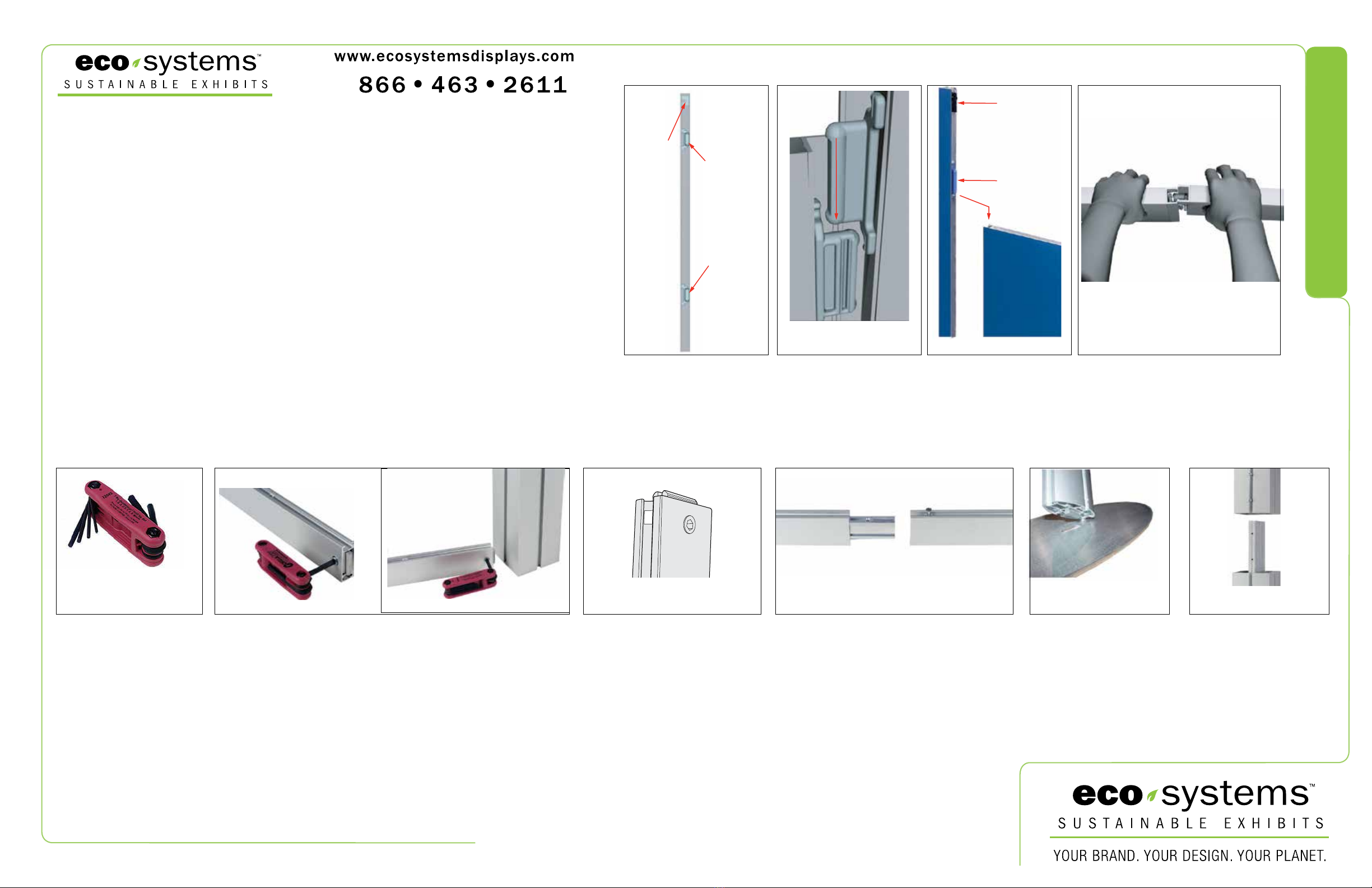
Each component has 2 clips,
the lower clip is ALWAYS
black. The top clip is color
coded to distinguish the level.
The color coded clip also
contains the numbered label.
Components connect together
by aligning them and sliding
downward connecting clips
together.
Configurations are assembled
from left to right, usually starting
with #1 and following the
numbered sequence.
The first level of components contains panel locks
that are located at the top of the panel for extra
stability and a seamless connection. When dis-
assembling panels, twist top connection slightly
and lift right panel upward.
Remove only (1) setscrew when disassembling.
Replace setscrew in extrusion after assembling it.
Before packing, replace setscrew in extrusion to
avoid losing it.
Attach base plate to vertical
extrusion using the lock provided.
Place base plate on ground and
set vertical post/lock in base plate
slot. Tighten lock with Mulit-tool.
When vertical extrusions are
packed in portable cases rather
than crates or tubs, they must be
broken down into smaller sections
which then require assembly.
Remove only (2) setscrews when
disassembling. Replace setscrews
in extrusion after assembling it.
Before packing, replace setscrews
in extrusion to avoid losing them.
Using Your Setup Instructions
Cleaning and Packing Your Display
The Setup Instructions are created specifically for your configuration.
They are laid out sequentially in levels, including exploded views, and a logical series of
detailed steps to assemble the main structure and components. We encourage you to study
the instructions before attempting to assemble your exhibit.
Each page reminds you to tighten the setscrews after disassembling your exhibit to prevent loss of
the locks and setscrews (see below in RED). This is VERY IMPORTANT.
1) Use care when cleaning aluminum extrusion or Eco Glass inserts. Use only non-abrasive cleaners.
2) When cleaning laminate inserts, countertops, or panels use mild cleansers and a soft material
such as cotton.
3) Keep all display components away from extreme heat and long exposure to sunlight to avoid
warping and fading.
4) Retain all packing material. It will make re-packing much easier and will reduce the likelihood of
shipping damage. Each Layer will be labeled with the packing order.
General Setup Instructions for Extrusion System
General Setup Instructions for ECO Panel System
Typical Connection (cont’d)
Most horizontal extrusion connections have a patented expandable lock.
This lock inserts into the groove of an opposing extrusion. Tightening the
lock with the Hex Key Tool expands the lock and creates a strong positive
connection.
Detail A Detail B Detail C Detail D Detail E
Setscrews
Connector
Cut Away View Of
Slide Clips Example of Connection Top View of Panels with Locks
Panel Lock
When Required
Color Coded Clip
w/ assembly number
Black Clip
is bottom of
panel
Level 1 = Blue
Level 2 = Red
Level 3 = Green
Level 4 = Black
7A
L
e
f
t
P
a
n
e
l
R
i
g
h
t
P
a
n
e
l
Panel Lock
When Required
Color Coded Clip
w/ assembly number
Left Hand
Grasps Panel
Firmly
With Right Hand Thumb
Close to Seam
Squeeze,
Push Forward,
And Lift


