Ecotap SLA_K 2 User manual

Electric vehicle charging station
Manual
Model: SLA_K 2.
For charging electric vehicles

2
MANUAL
© 2014 Ecotap® B.V
Version 2.01 / 2014
Table of Contents
1Introduction _________________________________________________________________ p. 3
2General _______________________________________________________________________ p. 4
2.1 Warranty p. 4
2.2 Symbols in this user / installation manual p. 4
3Device description __________________________________________________________ p. 5
3.1 Use p. 5
3.2 Accessories p. 5
3.3 Safety provisions p. 5
4Safety _________________________________________________________________________ p. 6
4.1 Safety regulations p. 6
5Mandatory checks before initial use ____________________________________ p. 7
6User / installation manual ________________________________________________ p. 8
6.1 Mounting the casing on the foundation p. 8
6.2 Installing the protective casing p. 9
6.3 Feeding the cable and installing it with strain relief p. 9
6.4 Connecting the power cable to the terminals p. 9
6.5 Connecting the grounding electrode / grounding conductor p. 9
6.6 Opening and closing the charging station p. 9
6.7 Installing the kWh meter p. 11
7Maintenance ________________________________________________________________ p. 14
8Transport and storage _____________________________________________________ p. 14
9In case of malfunctions ____________________________________________________ p. 14
10 Operation and use of charging station __________________________________ p. 15
11 Technical specifications ____________________________________________________ p. 16
12 Supplier contact information _____________________________________________ p. 16
13 EC declaration of conformity _____________________________________________ p. 17

3
1 Introduction
Thank you for opting for an Ecotap® charging station.
This manual is regarding the SLA-K 2 type charging station.
This manual contains important information for properly and safely installing and using
the charging station.
This charging station is designed for vehicles that are equipped with a mode 3 charging
system that complies with IEC 61815-1 (version 2.0) and a plug system that complies
with VDE-AR-E 2623-2-2. This combination of vehicle and station is the safest, which
will thus allow the vehicle to charge quickly and safely.
The entire charging station complies with the 2014/35/EU directive dealing with the
harmonisation of regulations regarding electric materials within certain voltage limits
(a recast of all previously published versions).
This manual explains how to safely install and use the charging station. This manual
was drawn up in such a way as to ensure the charging station’s maximum functioning
and lifespan.
This manual was drawn up with great care. However, should anything remain unclear
after reading it, please contact your supplier before you install the charging station.
We cannot guarantee that this charging station will function properly unless it is
installed by an authorised or certified installer / mechanic.
Read this manual carefully before you install or use the charging station. Save this
manual and store it near the station so that the instructions and safety regulations
will always be readily available.
© Copyright
No part of this publication may be copied, reproduced or saved in a retrieval system without Ecotap®B.V.’s
prior written consent.
This is an English translation of the original Dutch manual.
4
2General
2.1 Warranty
The Ecotap®B.V. General terms and conditions for delivery apply here.
Ecotap®B.V. cannot be held accountable for any injury or damage to goods should the charging
station be altered, damaged, refitted or expanded upon with other components, or not used in
accordance with the instructions and conditions set out here.
2.2 Symbols in this manual and on the charging station
SYMBOL
MEANING
Pay attention!
Important instruction.
Electrical hazard.
For maintenance: first disconnect the installation from its power supply and test it to
make sure there is no voltage left, before engaging in any maintenance activities.
Wear special gloves.
Disconnect the electrical installation from its power supply.
Reading this manual is mandatory.

5
3 Device description
3.1 Use
This charging station is especially designed for public areas.
The station can be installed in various environments: in paved areas, in open soil/sand, or in
asphalt surfaces. The following environments, however, are not suitable:
- Any area that could flood during high tide
- Loading quays
- Any slopes with an incline of 4% or more
3.2 Accessories
The following accessories will not be provided: tools, foundation.
3.3 Safety provisions
- 2 half euro profile cylinders
- Extra caps behind front cap
- 12 Volt control voltage
- Components comply with IP2 at least
- Strain reliefs
- 4 mm steel casing
- IP54 (lowest waterproof class for Mennekes outlets).

6
4 Safety
Read the following safety regulations carefully before you install and use the charging
station.
4.1 Safety regulations
Before you install the charging station, you must make sure the location is safe for all
bystanders. NEVER allow children onto this worksite. Never allow ANYONE who has nothing
to do with the work onto the worksite.
Never be distracted while you are performing the work.
Make sure you maintain a healthy posture at all times while doing the work.
Do not leave any tools or charging station components unattended.
Make sure any tools you are using are clean and dry.
Make sure that the charging station, tools and components will stay dry when it is raining.
Make sure that there is no danger of anyone tripping over objects or paving
while you are digging the hole for the foundation.
Make sure to wear good, suitable gloves for any special actions throughout the
entire installation and connection process.
Always check any measuring instruments you will be using to disconnect the
installation from its power supply before you use them, checking them several
times to make sure they are working properly.

7
5Mandatory checks before initial use
The following checks are mandatory before the charging station
goes live. NEVER use the charging station if one or more of the
checks indicate that the power supply or stability of the charging
station does not suffice. Check the insulation resistance of the
various conductors in accordance with NEN1010 provision 61.3.3.
Always perform the checks below before voltage is applied to the SLA_K
charging station.
- All of the activities listed below must be performed in accordance with NEN 3140.
- Check whether the terminals have been connected to the wiring in the right order.
- Check whether the conductors on the terminals have been screwed on properly (4 to 5
NM).
- Check whether the grounding connector has been connected to the coded terminal and
whether it has been connected to the grounding electrode or the supplied grounding
device. The entire grounding system must comply with the NEN1010/EU/35.
- Check whether the charging station is stable.
- Check whether the seals on the charging station’s caps have been installed properly
during installation (IP54).
- Check whether any actions still need to be performed, so that they may be performed
safely.
- Make sure there are no obstacles surrounding the worksite.
- Before any voltage is applied to the charging station, make sure to contact Ecotap® B.V.
by calling 0031 (0) 411-210210 so that we can activate that particular station’s
software; we will need the station’s unique code to do so.

8
6User / installation manual
6.1 Mounting the casing on the foundation
The foundation must be installed in a hole of 50x50 cm in size and 80 cm deep.
The bottom of the hole must be stable and flattened out properly.
Place the foundation in the hole and check whether it is level using a level.
You can correct any small deviations while you are closing the hole.
Place the charging station on the foundation without its 2 bent steel cap sections and mount
it using the bolts and nuts supplied (the nuts go on the top).
Leave the transparent lids on the front of the charging station in place for now.
Make sure the station faces the right way (i.e. the connecting side is at the front).
Close the hole using around 20 cm of soil/sand.
Install the cap in the back using the nuts that have been supplied.
See diagram 1.1 below.

9
6.2 Installing the protective casing
The protective casing (80cm) is supplied along with the foundation.
Once the casing has been mounted on the foundation, the clear plastic protective lid on the
bottom of the casing may be removed.
Install the casing bottom side-down and fix it in place using the support clamp.
(diagram 1.1)
6.3 Feeding the cable and installing it with strain relief
Feed the power cable through the protective casing.
Expose the wiring, but be careful not to expose too great a length.
Fit the cable clamp around the cable and fix it in place (3 Nm max).
(diagram 1.1)
6.4 Connecting the power cable to the terminals
Connect the phase conductors to the terminals marked L1 / L2 / L3 (4 to 5 Nm).
Connect the neutral conductor to the neutral terminal (blue) (4 to 5 Nm).
Connect the grounding conductor to the coded ground terminal (green) (4 to 5 Nm).
6.5 Connecting the grounding electrode/grounding conductor
Connect the connection cable’s grounding conductor to the specified grounding point (the
ground terminal).
If a grounding electrode has been installed, connect that to the ground terminal as well, as
shown in diagram 1.1 on page 9.
Perform the entire grounding process in accordance with the guidelines currently in force,
namely NEN1010/EU/35.
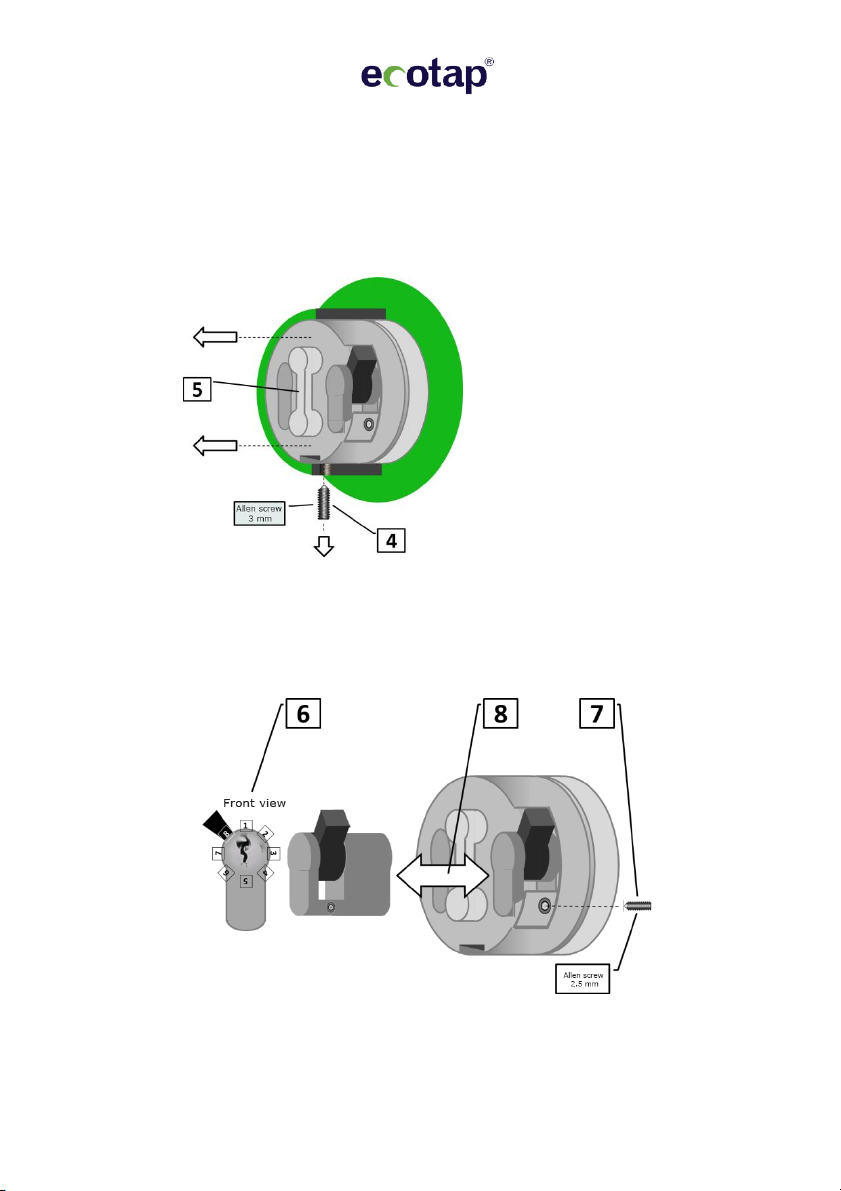
6.6 Opening and closing the charging station
1. Stick the key in the lock and turn clockwise.
2. Turn the whole lock unit with its two keyholes anticlockwise by 90 degrees.
3. Lift the cap (the front section with the
lock) up and off of the charging station.
10
Replacing the single euro cylinder
WARNING: Please note that you may only replace the lock cylinder for which you have the key. The lock cylinder for which you do not have a key may only be
accessed by Ecotap’s service team.
4. Unscrew the screws using a 3 mm Allen key.
5. Slide the whole cylinder, locks and all, out of the cap.
6. Make sure that the cylinder’s notch is aligned as shown in diagram 6 below.
7. Unscrew the screw using a 2.5 mm Allen key.
8. You can now replace the lock.
9. Screw everything back together in reverse order.

11
6.7 Installing the kWh meter
- Wiring diagram for type B23-112-10M ABB kWh meter
The wiring on the screw terminal has been labelled; connect the kWh meters
according to the diagram.

12
-Installing the type 112-10M ABB kWh meter
Five aspects of the ABB kWh meter must be checked and possibly adjusted:
menu default set to
Protoc Modbus Modbus
Boud 19200 38400
Addres links 001 003
Addres rechts 001 002
Parity Even None
There is a cap covering the display; open the cap, exposing the button. These three
buttons are used to navigate the meter’s menu:
To open the menu, press the OK button for 1 second. The display will now read rEG.
(Additional steps are on the next page.)
To open the menu, press the OK button for 1 second. The display will now read rEG.
(Additional steps are on page 4.) The OK button has different functions depending on how
long it is pressed for.
Pressing the OK button briefly just once will take you one menu level down. Pressing the OK
button for 1 second (i.e. long) will take you to the previous menu. If you have lost track of
what menu you are in, simply press the OK button for 1 second to return to the previous
menu; this works for all menus in the system. Simply repeat to return to the home screen.

13

14
7 Maintenance
Always disconnect the charging station from its power supply completely and
read the manual before performing any maintenance or fixing any malfunctions.
Repairs or replacements of components may only be done if using products that
are approved by the supplier. When in doubt, please contact Ecotap®first.
Repairs and replacements must always be performed by an authorised person / specialist.
The maintenance must always comply with and be performed in compliance with NEN3140
and NEN50110 low voltage EU directives.
Check the charging station for any leaks.
Test the heating element and the thermostat together to make sure they are working
correctly. The thermostat must be set to five degrees or to frost protection mode.
Check the connections on the power supply cable and ensure a fixed connection of between
4 and 5 Nm.
Treat any minor damage to the charging station with corrosion-resistant paint in the right
shades (Ecotap®green ral.6018 & white ral.9016).
Treat the cylinder locks with graphite powder or a suitable oil product if they require any
maintenance.
8 Transport and storage
Store the charging station (the core housing all of the technology) upright and prevent the
coating from being damaged; any such damage might result in corrosion. Provided that they
are properly protected to prevent them being damaged, the caps can be transported in a
variety of positions. The charging station should be stored in a dry, damp-free area.
9 In case of malfunctions
In case the SLA-K charging station is not functioning (properly), please contact the Ecotap®
24/7 helpdesk immediately (phone number: 0031 (0) 411-745020) or a licensed mechanic in
possession of measuring and testing equipment with auto simulation.
WARNING !
All work performed on and modifications made to the charging station must comply with
NEN1010 at the very least.

15
10 Operation and use of charging station
This charging station is operated via a charging pass.
The charging pass first needs to be registered in the Open Charge Point Protocol (OCPP).
This necessary registration can be completed by phone by calling Ecotap®B.V. at 0031 (0)
411-210210 during office hours.
As soon as the registration has been completed, the charging station can be operated with
any electric vehicle charging pass (EV charging pass) or other suitable passes, mobiles and
keys.
The charging station’s green light will blink at regular intervals when the station is not being
used.
Use:You start the procedure by holding the charging pass in front of the scanner; you will
hear a beep and the green light will start blinking.
First of all, the plug will be locked into the Mennekes charging socket.
The charging station will then communicate with the vehicle and the back office system, and
then once all safety regulations and payment arrangements have been checked, the
maximum amount of voltage permitted will be transmitted.
The charging procedure will now start automatically, and the light will turn blue.
When the charging process is finished and you hold your charging pass in front of the
scanner again, you will hear two beeps and the green light will start blinking until the plug is
unlocked.
You may now remove the plug.

16
11 Technical specifications
Weight of midsection: 23.5Kg
Weight of back cap: 9Kg
Weight of front cap: 10.5Kg
Total weight excl. foundation: 43Kg
Size: H1400mm D170mm B180mm
Height of plug connections: 1185mm
Power supply voltage: 230V / 400V 50Hz
Connection parameters: from 1 or 3 x 16A to 3 x 63A
Material thickness on caps: 3.4mm steel
Material thickness on protective casing: 4mm steel
Internal residual current device, 4-pole 40A 30mA type B* or A depending on the
installation area and need therefore. (NEN1010)
Anticorrosion treatment using EPD treatment and Dupont®coating systems, among other
things: 10-year warranty.
*) Depending on the area where it is being installed.
Ecotap® B.V. reserves the right to change any of the above technical specifications without prior
notice as the result of the ongoing innovative development of the machine. Moreover, the
technical specifications may differ from country to country.
12 Supplier contact information
Ecotap® B.V.
4 Industrieweg
5281 RW Boxtel, The Netherlands
phone: 0031 (0) 411-210 210
email: [email protected]

17
Table of contents
Other Ecotap Batteries Charger manuals


