ECS HDC-I User manual

Preface
Preface
Copyright
This publication, including all photographs, illustrations and software, is protected
under international copyright laws, with all rights reserved. Neither this manual, nor
any of the material contained herein, may be reproduced without written consent of
the author.
Version 1.0
Disclaimer
The information in this document is subject to change without notice. The manufac-
turer makes no representations or warranties with respect to the contents hereof and
specifically disclaims any implied warranties of merchantability or fitness for any
particular purpose. The manufacturer reserves the right to revise this publication and
to make changes from time to time in the content hereof without obligation of the
manufacturer to notify any person of such revision or changes.
Trademark Recognition
Microsoft, MS-DOS and Windows are registered trademarks of Microsoft Corp.
MMX, Pentium, Pentium-II, Pentium-III, Celeron are registered trademarks of Intel
Corporation.
Other product names used in this manual are the properties of their respective
owners and are acknowledged.
Federal Communications Commission (FCC)
This equipment has been tested and found to comply with the limits for a Class B
digital device, pursuant to Part 15 of the FCC Rules. These limits are designed to
provide reasonable protection against harmful interference in a residential installa-
tion. This equipment generates, uses, and can radiate radio frequency energy and, if
not installed and used in accordance with the instructions, may cause harmful inter-
ference to radio communications. However, there is no guarantee that interference
will not occur in a particular installation. If this equipment does cause harmful
interference to radio or television reception, which can be determined by turning the
equipment off and on, the user is encouraged to try to correct the interference by one
or more of the following measures:
• Reorient or relocate the receiving antenna
• Increase the separation between the equipment and the receiver
• Connect the equipment onto an outlet on a circuit different from that to
which the receiver is connected
• Consult the dealer or an experienced radio/TV technician for help
Shielded interconnect cables and a shielded AC power cable must be employed with
this equipment to ensure compliance with the pertinent RF emission limits govern-
ing this device. Changes or modifications not expressly approved by the system’s
manufacturer could void the user’s authority to operate the equipment.

ii
Preface
DeclarationofConformity
This device complies with part 15 of the FCC rules. Operation is subject to the
following conditions:
• This device may not cause harmful interference, and
• This device must accept any interference received, including interfer-
ence that may cause undesired operation
CanadianDepartmentofCommunications
This class B digital apparatus meets all requirements of the Canadian Interference-
causing Equipment Regulations.
Cet appareil numérique de la classe B respecte toutes les exigences du Réglement sur
le matériel brouilieur du Canada.
AbouttheManual
The manual consists of the following:
Chapter 1
Introducing the Motherboard
Chapter 2
Installing the Motherboard
Chapter 3
UsingBIOS
Chapter 4
Using the Motherboard Software
Describes features of the
motherboard.
Go to Hpage 1
Describes installation of
motherboard components.
Go to Hpage 7
Provides information on using the
BIOS Setup Utility.
Go to Hpage 21
Describes the motherboard soft-
ware.
Go to Hpage 41
Chapter 5
TroubleShooting Go to Hpage 45
Provides basic trouble shooting tips

iii
TT
TT
TABLE OF CONTENTSABLE OF CONTENTS
ABLE OF CONTENTSABLE OF CONTENTS
ABLE OF CONTENTS
Preface i
Chapter 1 1
IntroducingtheMotherboard 1
Introduction...................................................................................1
Feature............................................................................................2
Specifications................................................................................4
MotherboardComponents..........................................................5
Chapter 2 77
77
7
Installing the Motherboard 7
SafetyPrecautions............................................................................7
ChoosingaComputer Case.............................................................7
Installingthe Motherboardin a Case............................................7
CheckingJumperSettings...............................................................8
Setting Jumpers.................................................................8
Checking Jumper Settings...................................................9
Jumper Settings...................................................................9
InstallingHardware........................................................................10
Installing Memory Modules...............................................10
Expansion Slots..................................................................11
Connecting Optional Devices.............................................13
Installing a SATA Hard Drive..............................16
ConnectingI/ODevices................................................................17
ConnectingCaseComponents.....................................................18
Front Panel Header..............................................................20
Chapter 3 21
UsingBIOS 21
AbouttheSetup Utility................................................................ 21
The Standard Configuration..............................................21
Entering the Setup Utility....................................................21
Resetting the Default CMOS Values....................................22
UsingBIOS......................................................................................22
BIOS Navigation Keys.......................................................23
Main Menu........................................................................23
Advanced Menu..................................................................24
Chipset Menu......................................................................33
Frequency/Voltage Control Menu........................................35

iv
Boot Menu.........................................................................36
Security Menu....................................................................37
Save & Exit Menu..............................................................38
Updating the BIOS..............................................................40
Chapter 4 4141
4141
41
UsingtheMotherboardSoftware 41
AbouttheSoftware DVD-ROM/CD-ROM..................................41
Auto-installingunderWindows XP/Vista/7................................41
Running Setup....................................................................42
ManualInstallation.........................................................................44
UtilitySoftwareReference..............................................................44
Chapter 5 4545
4545
45
TroubleShooting 45
Startup problemsduring assembly...............................................45
Startup problemsafter prolonguse.............................................46
Maintenanceandcare tips.............................................................46
BasicTroubleshooting Flowchart................................................47

1
IntroducingtheMotherboard
Chapter1
IntroducingtheMotherboard
Introduction
Thank you for choosing the HDC-I motherboard. This is a high performance, en-
hanced function motherboard with onboard FT1 CPU for high-end business or per-
sonal desktop markets.
The motherboard is equipped with advanced full set of I/O ports in the rear panel,
including one DVI port, one eSATA port, one VGA port, six USB 2.0 ports, two USB
3.0 ports, one Bluetooth, one HDMI port, one LAN port, one SPDIFO port and
audio jacks for microphone, line-in and line-out.
This motherboard is based on AMD Hudson M1 FCH Chipset for best desktop
platform solution. Hudson M1 FCH is a single-chip, highly integrated, high perfor-
mance. This motherboard supports up to 8GB of system memory with single channel
DDR3 1066/800 MHz. High resolution graphics via one PCI Express X16 slot,
intended for Graphics Interface. One Mini PCI Express X1 slot is also supported. It
implements an EHCI compliant interface that provides ten USB 2.0 ports (six USB
2.0 ports at the rear panenl and two USB 2.0 headers supporting additional four USB
2.0 ports). It also implements extra USB 3.0 chip which provides two USB 3.0 ports
at the rear I/O with blue connectors. This motherboard integrates a Serial ATA host
controller, supporting four SATA ports with maximum transfer rate up to 6.0 Gb/s
each.

2
IntroducingtheMotherboard
Onboard LAN(Optional)
• Supports PCI ExpressTM 1.1
• Integrated 10/100/1000 transceiver
• Integrated Switching Regulator
• Wake-on-LAN and remote wake-up support
Audio
This motherboard may support either of the following Audio chipsets:
Feature
Processor
• TheAPU connects to the Fusion Controller Hub (FCH) through the Uni-
fied Media Interface (UMI) to provide connections to the different sys-
tem devices.
The AMD Hudson M1 FCH chipset is a single-chip with proven reliability and
performance.
Chipset
Memory
• Supports one PCI Express X16 slot (running at x4 mode)
• Supports one Mini PCI Express X1 slot
• Integrated SATA 6.0 Gb/s Host Controller
• Ten USB 2.0 ports supported
• SupportsUnified Media interface(UMI), SMBus controller,and High Defi-
nitionAudio
• Supports Serial Peripheral Interface (SPI)
• Enhanced DMA Controller, power management, hardware monitoring,
interrupt controller, and clock function.
• Supports DDR3 1066/800 SDRAM with Dual-channel architecture
• Accommodates two unbuffered DIMMs
• 2 x 240-pin DDR3 SDRAM sockets support up to 8 GB
• 5.1 Channel High Definition Audio Codec
• ADCs support 44.1k/48k/96k/192kHz sample rate
• Exceeds Microsoft Windows Logo Program (WLP) Require
ments
• Power support: Digital: 3.3 V; Analog: 5.0V
• The onboard AMD FT1 processor combines the central processing unit
(CPU) with the graphics processing unit (CPU) in a single-chipAcceler-
ated Processing Unit (APU) package.
This motherboard uses onboard AMD FT1 CPU that carries the following fea-
tures:
• Supports PCI ExpressTM 1.1
• Integrated 10/100 transceiver
• Integrated Linear Regulator
• Wake-on-LAN and remote wake-up support

3
IntroducingtheMotherboard
The motherboard comes with the following expansion options:
Expansion Options
• OneSPDIFOport
• One Bluetooth
• One DVI port
• One VGA port
• SIX USB 2.0 ports and two USB 3.0 ports
• One LAN port
• One eSATA port
• OneHDMIport
• Audio jacks for microphone, line-in and line-out
The motherboard has a full set of I/O ports and connectors:
Integrated I/O
1.Some hardware specifications and software items are subject to change
without prior notice.
2.Due to chipset limitation, we recommend that motherboard be oper-
ated in the ambiance between 0 and 50°C.
The firmware can also be used to set parameters for different processor clock
speeds.
• Power management
• Wake-up alarms
• CPUparameters
• CPUandmemorytiming
BIOS Firmware
This motherboard uses AMI BIOS that enables users to configure many system
features including the following:
• One PCI Express X16 slot (running at x4 mode) for Graphics Interface
• One Mini PCI Express X1 slot (with optional wireless card)
• Four 7-pin SATA connectors

4
IntroducingtheMotherboard
• Onboard AMD FT1 Processor
• VT1708B
• AR8151 Gigalan (Co-lay 10/100 AR8152)
• OneSPDIFOport
• One Bluetooth
• One DVI port
• One VGA port
• SIX USB 2.0 ports and two USB 3.0 ports
• One LAN port
• One eSATA port
• OneHDMIport
• Audio jacks for microphone, line-in and line-out
• 1 x 24-pin ATX Power Supply connector
• 4 x Serial ATA 6.0 Gb/s connectors
• 2 x USB 2.0 headers support additional 4 USB 2.0 ports
• 1 x Clear CMOS header
• 1 x Front panel header
• 1 x Front panel audio header
• CPU FAN/SYS FAN connectors
• 1 x Speaker header
• 1 x CASE Open header
• 1 x LVDS header (Optional)
Audio
LAN
RearPanelI/O
InternalI/O
Connectors &
Headers
• AMIBIOS with 16Mb SPI Flash ROM
• Supports Plug and Play,ACPI & DMI, S1/STR(S3)/STD(S4),
Hardware monitor, Over-Clocking, Dual Dispaly
• Audio, LAN, can be disabled in BIOS
• F11 hot key for boot up devices option
SystemBIOS
Form Factor • Mini-ITXSize, 170mm x 170mm
CPU
Specifications
• AMD Hudson M1 chipset
• Dual-channel DDR3 memory architecture
• 2 x 240-pin DDR3 DIMM sockets support up to 8 GB
• SupportsDDR31066/800 DDR3 SDRAM
• 1 x PCI Express X16 slot (running at x4 mode)
• 1 x Mini PCI Express X1 slot (with optional wireless card)
• Supported by AMD Hudson M1 chipset
• 4 x Serial ATA 6.0 Gb/s devices
Chipset
Memory
Expansion
Slots
Storage
5
IntroducingtheMotherboard
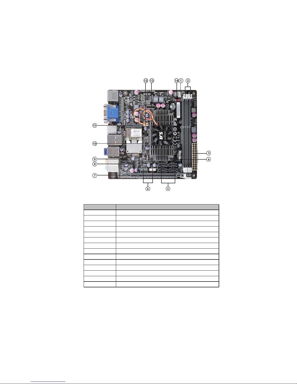
MotherboardComponents
Table of Motherboard Components
This concludes Chapter 1. The next chapter explains how to install the motherboard.
LABEL COMPONENTS
1. CPU_FAN CPU cooling fan connector
2. DDR3_1~2 240-pin DDR3 SDRAM slots
3. ATX_POWER Standard 24-pin ATX power connector
4. SPK External speaker header
5. SATA1~4 Serial ATA 6.0 Gb/s connectors
6. F_USB1~2 Front panel USB 2.0 header (F_USB1 supports EZ charger)
7. PCIE16X PCI Express x16 slot (running at x4 mode)
8. F_PANEL Front panel switch/LED header
9. F_AUDIO Front panel audio header
10. CASE CASE open header
11. MINIPCIE Mini PCI Express x1 slot (with optional wireless card)
12. SYS_FAN System cooling fan connector
13. LVDS LVDS header (Optional)
14. CLR_CMOS Clear CMOS jumper

6
IntroducingtheMotherboard
Memo

7
Installing the Motherboard
Chapter 2
Installing the Motherboard
SafetyPrecautions
• Follow these safety precautions when installing the motherboard
• Wear a grounding strap attached to a grounded device to avoid dam-
age from static electricity
• Discharge static electricity by touching the metal case of a safely
grounded object before working on the motherboard
• Leave components in the static-proof bags they came in
• Hold all circuit boards by the edges. Do not bend circuit boards
ChoosingaComputer Case
There are many types of computer cases on the market. The motherboard complies
with the specifications for the Mini ITX system case. First, some features on the
motherboard are implemented by cabling connectors on the motherboard to indica-
tors and switches on the system case. Make sure that your case supports all the
features required. Secondly, this motherboard supports four enhanced SATA drives.
Make sure that your case has sufficient power and space for all drives that you intend
to install.
Most cases have a choice of I/O templates in the rear panel. Make sure that the I/O
template in the case matches the I/O ports installed on the rear edge of the
motherboard.
This motherboard carries a Mini ITX form factor of 170 x 170 mm. Choose a case
that accommodates this form factor.
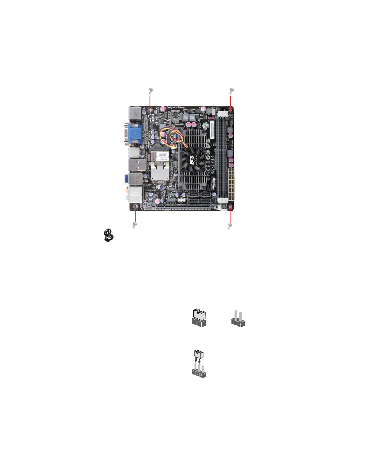
InstallingtheMotherboardina Case
Refer to the following illustration and instructions for installing the motherboard in
a case.
Most system cases have mounting brackets installed in the case, which correspond
the holes in the motherboard. Place the motherboard over the mounting brackets
and secure the motherboard onto the mounting brackets with screws.
Ensure that your case has an I/O template that supports the I/O ports and expansion
slots on your motherboard.
8
Installing the Motherboard
CheckingJumperSettings
This section explains how to set jumpers for correct configuration of the motherboard.
SettingJumpers
Use the motherboard jumpers to set system configuration options. Jumpers with
more than one pin are numbered. When setting the jumpers, ensure that the jumper
caps are placed on the correct pins.
The illustrations show a 2-pin jumper.
When the jumper cap is placed on both
pins, the jumper is SHORT. If you re-
move the jumper cap, or place the jumper
cap on just one pin, the jumper is OPEN.
This illustration shows a 3-pin jumper.
Pins 1 and 2 are SHORT.
SHORT OPEN
Do not over-tighten the screws as this can stress the motherboard.
9
Installing the Motherboard
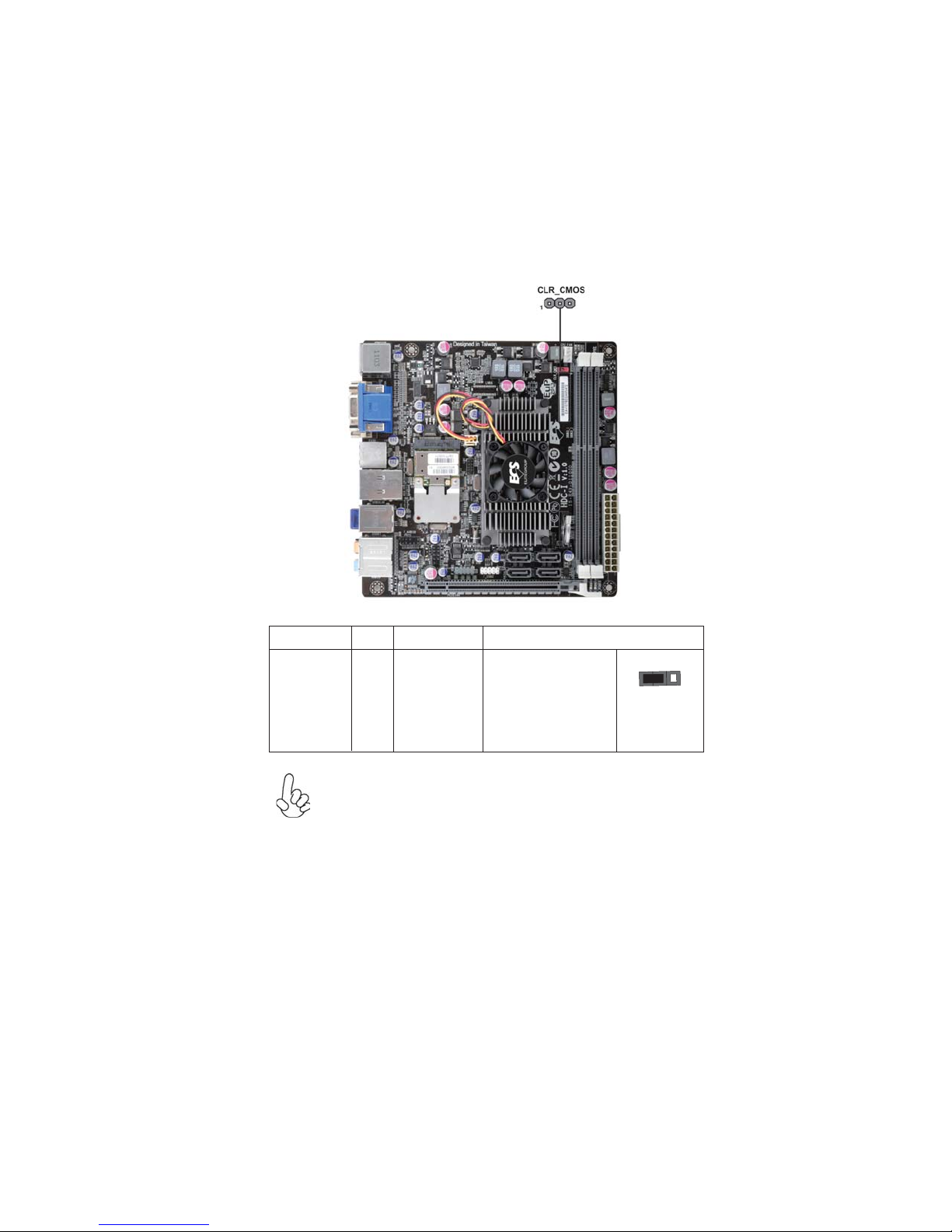
Checking Jumper Settings
The following illustration shows the location of the motherboard jumpers. Pin 1 is
labeled.
JumperSettings
To avoid the system instability after clearing CMOS, we recommend
users to enter the main BIOS setting page to “Load Default Settings”
and then “Save and Exit Setup”.
Jumper Type Description Setting (default)
CLR_CMOS 3-pin Clear CMOS
1-2: NORMAL
2-3: CLEAR
Before clearing the
CMOS, make sure to
turn off the system.
CLR_CMOS
1
10
Installing the Motherboard
Installing Memory Modules
This motherboard accommodates two memory modules. It can support two 240-pin
DDR3 1066/800. The total memory capacity is 8 GB.
You must install at least one module in any of the two slots. The total memory
capacity is up to 8 GB.
Do not remove any memory module from its antistatic packaging
until you are ready to install it on the motherboard. Handle the
modules only by their edges. Do not touch the components or metal
parts. Always wear a grounding strap when you handle the modules.
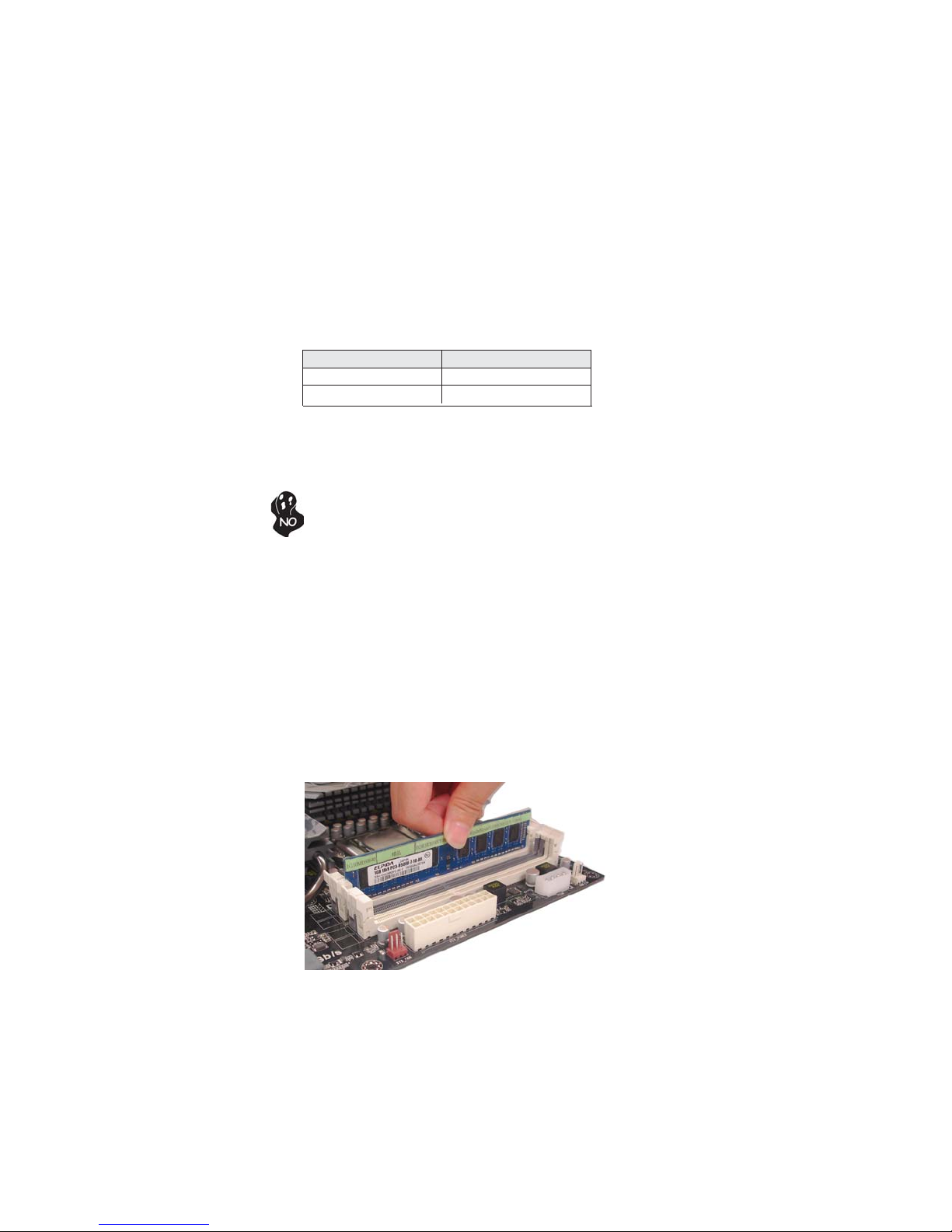
Installation Procedure
Refer to the following to install the memory modules.
1 This motherboard supports unbuffered DDR3 SDRAM.
2 Push the latches on each side of the DIMM slot down.
3 Align the memory module with the slot. The DIMM slots are keyed with
notches and the DIMMs are keyed with cutouts so that they can only be
installed correctly.
4 Check that the cutouts on the DIMM module edge connector match the
notches in the DIMM slot.
5 Install the DIMM module into the slot and press it firmly down until it
seats correctly. The slot latches are levered upwards and latch on to
the edges of the DIMM.
6 InstallanyremainingDIMM modules.
DDR3 SDRAM memory module table
Memory module Memory Bus
* For reference only
InstallingHardware
DDR3 800 400 MHz
DDR3 1066 533 MHz
11
Installing the Motherboard
Installing Add-on Cards
The slot on this motherboard is designed to hold expansion card and connect it to the
system bus. Expansion slot is a mean of adding or enhancing the motherboard’s
features and capabilities. With these efficient facilities, you can increase the
motherboard’s capabilities by adding hardware that performs tasks that are not part
of the basic system.
Before installing an add-on card, check the documentation for the
card carefully. If the card is not Plug and Play, you may have to
manually configure the card before installation.
The PCI Express x16 slot with x4 bandwith is fully compliant to
the PCI Express Base Specification revision 2.0.
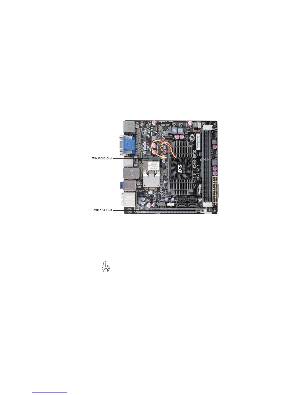
PCIE16X Slot
Expansion Slots
The Mini PCI Express x1 slot is for extending usage, such as wire-
less card or TV card.
MINIPCIE Slot
12
Installing the Motherboard
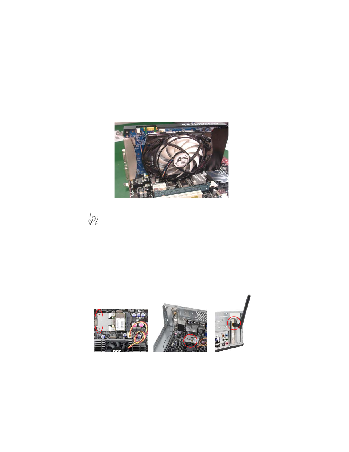
Follow these instructions to install an add-on card:
1 Remove a blanking plate from the system case corresponding to the
slot you are going to use.
2 Install the edge connector of the add-on card into the expansion slot.
Ensure that the edge connector is correctly seated in the slot.
3 Secure the metal bracket of the card to the system case with a screw.
For some add-on cards, for example graphics adapters and network adapt-
ers, you have to install drivers and software before you can begin using the
add-on card.
* For reference only
Follow these instructions to install a wireless card:
1 Remove a blanking plate from the system case, and insert the wireless
card into the MINIPCIE slot rightwards, then tighten the two screws
(Please refer to Picture 1).
2 Press the metal connector of the cable into the connector on the wire-
less card. Ensure that the metal connector is correctly seated (Please
refer to Picture 2).
3 Make the other end of the cable (with a gold screw) through the upper
hole of the bracket, and tighten the antenna on to the gold screw after
installing a metal gasket on the screw (Please refer to Picture 3).
Picture 1 Picture 2 Picture 3
13
Installing the Motherboard
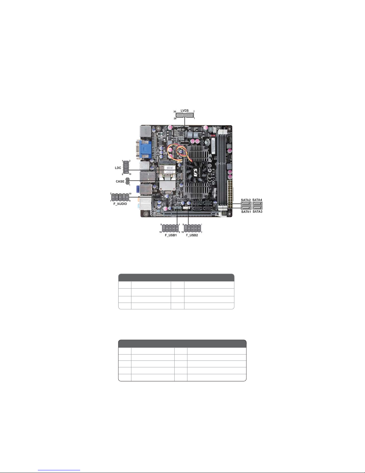
Connecting Optional Devices
Refer to the following for information on connecting the motherboard’s optional
devices:
SATA1~4: SerialATAIII connectors
These connectors are used to support the Serial ATA devices for the data transfer
rates (6.0 Gb/s), simpler disk drive cabling and easier PC assembly. It eliminates
limitations of the current Parallel ATA interface. But maintains register compatibil-
ity and software compatibility with Parallel ATA.
F_AUDIO:Front Panel Audio header for Azalia
This header allows the user to install auxiliary front-oriented microphone and line-
out ports for easier access.
1PORT 1L 2AUD_GND
3PORT 1R 4PRESENCE#
5PORT 2R 6SENSE_SEND
7AUD_GND 8KEY
Pin Signal Name Pin Signal Name
9PORT 2L 10 SENSE_SEND
1Ground 2 TX+
3TX- 4 Ground
5RX- 6 RX+
7Ground - -
Pin Signal NamePin Signal Name
14
Installing the Motherboard
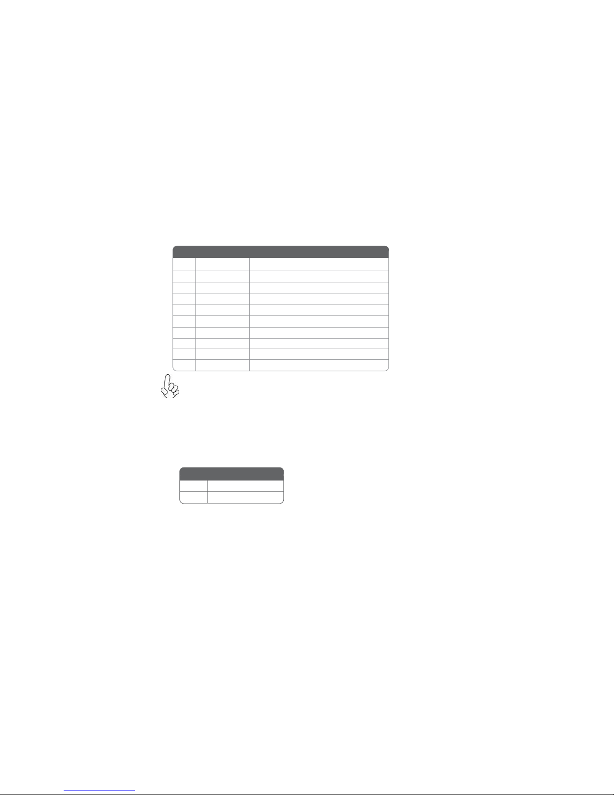
F_USB1~2:FrontPanelUSB2.0headers (F_USB1 supports EZ charger)
The motherboard has two USB 2.0 ports installed on the rear edge I/O port array.
Additionally, some computer cases have USB 2.0 ports at the front of the case. If you
have this kind of case, use auxiliary USB 2.0 connectors to connect the front-
mounted ports to the motherboard.
CASE: Chassis Intrusion Header
This detects if the chassis cover has been removed. This function needs a chassis
equipped with instrusion detection switch and needs to be enabled in BIOS.
Short Chassis cover is removed
Open Chassis cover is closed
Pin 1-2 Function
Unlike F_USB2 in this motherboard, F_USB1 supports EZ charger technology, pro-
vides about 1A current than general USB port in off mode for USB devices. It is useful
and excellent, especially for the iPhone, iPad and iPod touch devices that need a
large amount of current for faster recharging within less time.
Please make sure that the USB cable has the same pin assignment as
indicated above. A different pin assignment may cause damage or system
hang-up.
1USBPWR Front Panel USB Power
2USBPWR Front Panel USB Power
3USB_FP_P0- USB Port 0 Negative Signal
4USB_FP_P1- USB Port 1 Negative Signal
5USB_FP_P0+ USB Port 0 Positive Signal
6USB_FP_P1+ USB Port 1 Positive Signal
7GND Ground
8GND Ground
9Key No pin
10 USB_FP_OC0 GND
Pin Signal Name Function

15
Installing the Motherboard
LVDS: LVDS connector (Optional)
Pin Signal Name Pin Signal Name
1VDD 2VDD
5V_LED 6V_LED
7GND 8GND
9PWM_LED 10 EN_LED
11 USB_VCC 12 USB_D-
13 USB_D+ 14 USB_GND
15 V_EDID 16 GND
17 RXIN0- 18 RXIN0+
19 GND 20 RXIN1-
21 RXIN1+ 22 GND
23 RXIN2- 24 RXIN2+
3GND 4USB_GND
25 GND 26 RXCLK+
27 RXCLK- 28 GND
29 DATA-EDID 30 CLK-EDID

16
Installing the Motherboard
Installing a SATAHard Drive
This section describes how to install SATA connectors.
Refer to the illustration below for proper installation:
This motherboard does not support the “Hot-Plug” function.
1 Attach either cable end to the connector on the motherboard.
2 Attach the other cable end to the SATA hard drive.
3 Attach the SATA power cable to the SATA hard drive and connect the
other end to the power supply.
SATA cable (optional) SATA power cable (optional)
AboutSATAConnectors
Your motherboard features four SATA connectors supporting a total of four drives.
SATA refers to Serial ATA (Advanced Technology Attachment) is the standard inter-
face for the IDE hard drives which are currently used in most PCs. These connectors
are well designed and will only fit in one orientation. Locate the SATA connectors on
the motherboard and follow the illustration below to install the SATA hard drives.
Installing SerialATA Hard Drives
To install the Serial ATA (SATA) hard drives, use the SATA cable that supports the
Serial ATA protocol. This SATA cable comes with an SATA power cable. You can
connect either end of the SATA cable to the SATA hard drive or the connector on the
motherboard.
Table of contents
Other ECS Motherboard manuals


