4. Operating Instructions
* Disconnect the tubes from the PumpVentValve aswell
asfrom the ControllerVentValve.
* Pull out all plugs from the Electrical Supply Unit.
* Remove the Vacuum Controller from the Support Post
after loosening the clamp assembly.
* Remove the Valve Support Post from the Controller
Support Post after loosening the clamp assembly.
* Removethe Controller Support Postfrom the Baseplate:
-Loosen the Allen screw at the foot of the Vacuum Con-
troller Support Post.
-Slide it out of the BaseplateMounting Slot.
Assembly
* Mount the existing controller onto the new Controller
Support Post: Slide the Vacuum Controller (more ex-
actly: its clamping assembly) into theVacuum Controller
Support Post Mounting Slot andfix theVacuum Control-
ler by tightening the Allen screw.
* SlidetheVacuum Controller Support Post (more exactly:
its clamping assembly) into the BaseplateMounting Slot.
* Fix the Vacuum Controller Support Post by tightening
the Allen screw at the foot of the Support Post.
* Mount theValve Support Post onto the Controller Sup-
port Post.
* Slidethe holding device for theVacuumValves(including
VacuumValves) onto the Valve Support Post Mounting
Slot and fix the device with help of the clampingassem-
bly.
* Tubing of two headed pumps see figure 12.When con-
necting single head pumps,study the Information Sheet
that accompanies the accessories. Choose tube mate-
rial which is resistant to the media being used.
* Electrical connection: seesection3.5.1.
4.1 General Notes
Before using the vacuum pump or the D-LAB system please
observe the following points:
* Choose a safe location (flat surface) for the equipment.
* Ensure that the vacuum pump is securely fastened to
the Baseplate.The two locating pins underneath the pump
must be locked in position.
* Laboratory equipment or additional components con-
nected to a D-LAB -pump or a D-LAB -system must
be compatible with the physical capabilities of the pump.
* When using the high performance condenser the sys-
tem must be connected to a cold water supply or a re-
circulating cooler.
* When using two Vacuum Controllers: two controllers
should only be used with gases which can be mixed safely
together.
* Don't operate the pump/D-LAB-system in an atmos-
phere containing explosive gases.
Before getting started:
* Specific safety instructions for the media being handled
must be observed.
* Observe all safety regulations when handling: corrosive,
explosive, microbiological, radioactive, toxic and other
dangerous materials.
* Ensure the pump outlet is not closed or restricted and
adequate ventilation allowed.
If using a Condenser:
* Ensure that the vapour outlet on the top of the con-
denser isnever blocked (akink in the exhaust hose could
causepressure build up).
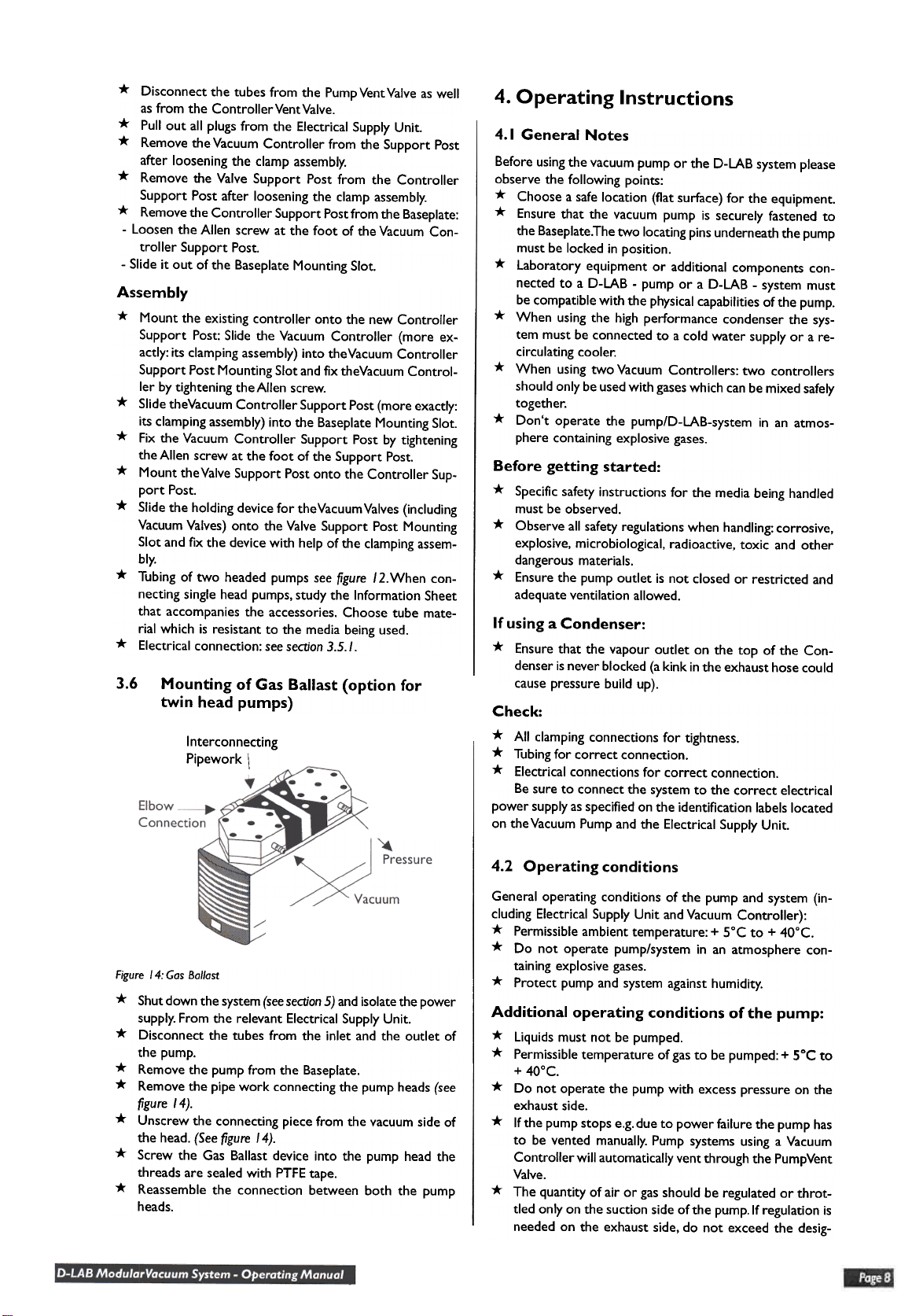
3.6 Mounting of Gas Ballast (option for
twin head pumps)
Interconnecting
Pipework \
Check:
* All clamping connections for tightness.
* Tubingfor correct connection.
* Electrical connections for correct connection.
Be sure to connect the system to the correct electrical
power supplyasspecified on the identification labelslocated
on theVacuum Pump and the Electrical Supply Unit.
4.2 Operating conditions
Figuret4:GasBallast
* Shutdown the system(seesection5) andisolatethe power
supply.From the relevant Electrical SupplyUnit.
* Disconnect the tubes from the inlet and the outlet of
the pump.
* Remove the pump from the Baseplate.
* Remove the pipe work connecting the pump heads(see
figure 14).
* Unscrew the connecting piece from the vacuum side of
the head. (Seefigure 14).
* Screw the Gas Ballast device into the pump head the
threads are sealedwith PTFEtape.
* Reassemble the connection between both the pump
heads.
General operating conditions of the pump and system {in-
cluding Electrical Supply Unit andVacuum Controller):
* Permissible ambient temperature: + 5°C to + 40°C.
* Do not operate pump/system in an atmosphere con-
taining explosive gases.
* Protect pump and system against humidity.
Additional operating conditions of the pump:
* Liquids must not be pumped.
* Permissibletemperature of gasto be pumped: + 5°C to
+ 40°C.
* Do not operate the pump with excess pressure on the
exhaust side.
* Ifthe pump stops e.g.due to power failure the pump has
to be vented manually.Pump systems using a Vacuum
Controller will automatically vent through the PumpVent
Valve.
* The quantity of air or gasshould be regulated or throt-
tled only on the suction side of the pump.If regulation is
needed on the exhaust side, do not exceed the desig-


