Efco BC 270 - DS 2700 Assembly instructions

en
fr
es
OPERATOR’S INSTRUCTION MANUAL
MANUEL D’UTILISATION ET D’ENTRETIEN
MANUAL DE INSTRUCCIONES
DS 2700 (1.66 cu.in) - DS 3000 (1.86 cu.in)


English 3
Français 33
Español 65


en
3
To correctly use the brush cutter and prevent
accidents, do not start work without having
rst carefully read this manual. You will nd
explanations concerning the operation of the
various parts plus instructions for necessary
checks and relative maintenance.
Note: Illustrations and specications
in this manual may vary according to
Country requirements and are subject to
change without notice by the
manufacturer.
THE OPERATOR’S MANUAL
Your operator’s manual is for your protection.
READ IT. Keep it in a safe place for reference.
Know what you are doing before you begin
assembly of the unit. Proper preparation and
upkeep go hand-in-hand with satisfactory
performance of the brush cutter and safety.
Contact your dealer or the distributor for your
area if you do not understand any of the
instructions in this manual.
In addition to the operating instructions, this
manual contain paragraphs that require your
special attention.
Such paragraphs are marked with the
symbols described below:
Warning: where there is a risk of an accident
or personal injury or serious damage to
property.
Caution: where there is a risk of damaging
the machine or its individual components.
WARNING - To ensure safe and
correct operation of the brush
cutter, this operator’s manual
should always be kept with or
near the machine. Do not lend or
rent your brush cutter without the
operator’s instruction manual.
WARNING: Allow only persons
who understand this manual to
operate your brush cutter.
INTRODUCTION

en
4
TABLE OF CONTENTS
PRODUCT IDENTIFICATION
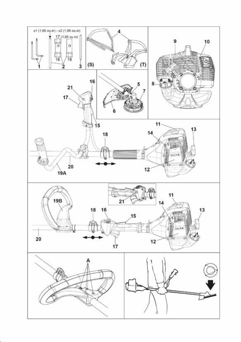
Brush Cutter Components ........................................... 5
SAFETY
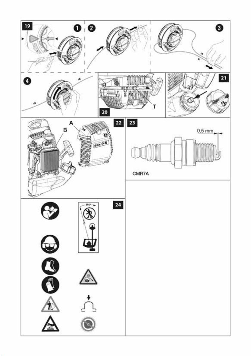
Understanding Safety Symbols ....................................... 5
State and Local Requirements ........................................ 6
SAFETY RULES
Basic Safety Precautions . . . . . . . . . . . . . . . . . . . . . . . . . . . . . . . . . . . . . . . . . . . . 7
Fuel Handling ..................................................... 8
Operation and Safety . . . . . . . . . . . . . . . . . . . . . . . . . . . . . . . . . . . . . . . . . . . . . . . 8
Precautions Against Kickout.......................................... 9
Maintain Control ................................................... 9
Safety Features ................................................... 10
Recommended Cutting Attachments ................................... 10
Safety equipment checking .......................................... 11
Precautions to Reduce Vibration Risk .................................. 11
Maintenance Precautions............................................ 11
ASSEMBLY
Assembling the Safety Guard......................................... 13
Assembling the cutting attachment..................................... 13
Assembling the handle ............................................. 14
Assembling the bike handle . . . . . . . . . . . . . . . . . . . . . . . . . . . . . . . . . . . . . . . . . . 14
Approved power tool attachment ...................................... 14
OPERATION
Fueling .......................................................... 15
Preparation for Cutting .............................................. 16
Starting the Engine................................................. 18
Breaking-in the Engine .............................................. 19
Stopping the Engine ................................................ 19
Working Techniques ................................................ 20
MAINTENANCE
Maintenance Chart ................................................. 24
Cutting Attachment Maintenance . . . . . . . . . . . . . . . . . . . . . . . . . . . . . . . . . . . . . . 25
Carburetor Adjustment . . . . . . . . . . . . . . . . . . . . . . . . . . . . . . . . . . . . . . . . . . . . . . 26
Fuel Filter ........................................................ 27
Air Filter ......................................................... 27
Starter Unit ....................................................... 27
Engine .......................................................... 27
Spark Plug ....................................................... 27
Mufer........................................................... 28
Bevel Gear . . . . . . . . . . . . . . . . . . . . . . . . . . . . . . . . . . . . . . . . . . . . . . . . . . . . . . . 28
Guard . . . . . . . . . . . . . . . . . . . . . . . . . . . . . . . . . . . . . . . . . . . . . . . . . . . . . . . . . . . 28
TROUBLESHOOTING
Using Troubleshooting Chart ......................................... 30
STORAGE
Storing Brush cutter ................................................ 31
TECHNICAL DATA
DS 2700 - DS 3000 ................................................ 31

en
5
PRODUCT IDENTIFICATION
MAIN COMPONENTS (Fig.1)
1÷3 - Tools supplied
4 - Harness
5 - Bevel gear
6 - Curved guard
7 - Nylon line head
8 - Fuel tank cap
9 - Purge Bulb
10 - Muer guard
11 - Spark plug
12 - Air lter
13 - Starter Handle
14 - Choke Lever
15 - Throttle trigger lockout
16 - STOP button
17 - Throttle lever
18 - Harness attachment
19 - Handle
20 - Shaft arm
21 - Button half-throttle
SAFETY
- This symbol indicates Warning,
and Caution.
- Your manual contains special
messages to bring attention
to potential safety concerns,
machine damage as well as
helpful operating and servicing
information. PLEASE READ
ALL THE INFORMATION
CAREFULLY TO AVOID INJURY
AND MACHINE DAMAGE.
- Wear eye, hearing and head
protection when operating this
equipment.
- Wear non-slip, heavy-duty
protective gloves when handling
the brush cutter and blades.
- Wear safety strong shoes or
boots having skid-proof sole and
anti-piercing insert.
- Be aware that objects can be
thrown.
- Keep bystanders away 50 ft (15
m).
- Warning! Kickback it’s danger.
- Purge bulb.
- WARNING – The surface can be
hot.
Understanding Safety Symbols

en
6
SAFETY
State and Local Requirements
The engine is NOT equipped with a
Spark Arrester System complying with
the requirements of SAE Recommended
Practice J335 and California Codes 4442
and 4443. All national forest land and
land managed by the states of California,
Maine, Washington, Idaho, Minnesota,
New Jersey and Oregon require internal
combustion engines to be equipped with
a spark arrester screen by law. Other
states and federal agencies are enacting
similar regulations.
Operating this engine in a state or locale
where such regulations apply, could result in
a violation of the law.
Note: When using a brush cutter for
logging purposes, refer to Code of Federal
Regulations, Parts 1910 and 1928.
WARNING: The ignition system
of your unit produces an
electromagnetic eld of a very low
intensity. This eld may interfere
with some pacemakers. To reduce
the risk of serious or fatal injury,
persons with pacemaker should
consult their physician and the
pacemaker manufacturer before
operating this tool.
WARNING: Mufer surfaces
are very hot during and after
operation of the brush cutter,
keep all body parts away from the
mufer. Serious burns may occur
if contact is made with the mufer.
WARNING: Exposure to vibrations
through prolonged use of gasoline
powered hand tools could cause
blood vessel or nerve damage
in the ngers, hands, and wrists
of people prone to circulation
disorders or abnormal swellings.
Prolonged use in cold weather
has been linked to blood vessel
damage in otherwise healthy
people. If symptoms occur such as
numbness, pain, loss of strength,
change in skin colour or texture,
or loss of feeling in the ngers,
hands, or wrists, discontinue the
use of this tool and seek medical
attention.
WARNING: The engine exhaust
from this product contains
chemicals known to the State of
California to cause cancer, birth
defects or other reproductive
harm.
Operate your brush cutter outdoors
only in a well ventilated area.
WARNING: Under no
circumstances may the design of
the machine be modied. Always
use genuine accessories. Non-
authorized modications and/or
accessories can result in serious
personal injury or the death of
the operator or others. Your
warranty may not cover damage
or liability caused by the use of
non-authorized accessories or
replacement parts.
WARNING: A brush cutter or
trimmer can be dangerous if used
incorrectly or carelessly, and can
cause serious or fatal injury to the
operator or others. It is extremely
important that you read and
understand the contents of this
operator’s manual.

en
7
SAFETY RULES
Basic Safety Precautions
• Read this manual carefully until you
completely understand and can follow all
safety rules, precautions, and operating
instructions before attempting to use the
unit.
• Restrict the use of your brush cutter to
adult users who understand and can follow
safety rules, precautions, and operating
instructions found in this manual. Minors
should never be allowed to use a brush
cutter.
• Do not handle or operate a brush cutter
when you are fatigued, ill, or upset, or if you
have taken alcohol, drugs, or medication.
You must be in good physical condition
and mentally alert. Brush cutter work is
strenuous. If you have any condition that
might be aggravated by strenuous work,
check with your doctor before operating a
brush cutter. Be more cautious before rest
periods and towards the end of your shift.
• Keep children, bystanders, and animals a
minimum of 50 feet (15 meters) away from
the work area. Do not allow other people
or animals to be near the brush cutter when
starting or operating the brush cutter.
• Major cases of brush cutter accidents
happen when the blade or thrown objects
hits the operator. While working with the
brush cutter, always use safety protective
approved clothing. The use of protective
clothing does not eliminate injury risks,
but reduces the injury effects in case of
accident. Consult your trusted supplier
to choose equipment in compliance
with legislation. The clothing must be
proper and not an obstacle. Wear adherent
protective clothing. Protective jackets and
dungarees leggings are ideal. Do not
wear clothes, scarves, ties or bracelets that
may get stuck into twigs. Tie up and protect
long hair (example with foulards, cap,
helmets, etc.). Safety boots having skid-
proof sole and anti-piercing insert. Wear
protective goggles or face screens. Use
protections against noises: for example,
noise reduction ear guards or earplugs.
The use of protections for the ear requires
much more attention and caution, because
the perception of audible warning signals
(screaming, alarms, etc.) is limited. Always
remove your hearing protection as soon as
the engine stops. Wear gloves that permit
the maximum absorption of vibrations.
• Only allow others to use this brush cutter
who have read this Operator’s Manual or
received adeguate instructions for the safe
and proper use of this brush cutter.
• Check the brush cutter each day to ensure
that each device, whether for safety or
otherwise, is functional.
• Never use a damaged, modied, or
improperly repaired or assembled brush
cutter. Do not remove, damage or
deactivate any of the safety devices. Only
use cutting tools indicated in the table
(page 10). Always replace cutting tools or
safety devices immediately if it becomes
damaged, broken or is otherwise removed.
• Carefully plan your operation in advance.
Do not start cutting until you have a clear
work area, secure footing, and a planned
retreat path.
• All brush cutter service, other than the
operations shown in the present manual,
have to be performed by competent
personnel.
• The brush cutter must only be used for
trimming grass, grass clearing and / or
forestry clearing. It is unadvisable to cut
other types of material.
• It is unadvisable to hitch tools or applications
to the P.t.o. that are not specied by the
manufacturer.

en
8
Fuel Handling
WARNING: Gasoline is an
extremely flammable fuel. Use
extreme caution when handling
gasoline or fuel mix. Do not
smoke or bring any re or ame
near the fuel or the brush cutter.
WARNING: Fuel and fuel fumes
can cause serious injury when
inhaled or allowed to come in
contact with the skin. For this
reason observe caution when
handling fuel and make sure there
is adequate ventilation.
WARNING: Beware of carbon
monoxide poisoning.
WARNING! – Mufers tted with
catalytic converters get very hot
during use and remain so for
some time after stopping. This
also applies at idle speed. Contact
can result in burns to the skin.
Remember the risk of re!
• To reduce the risk of fire and burn
injury, handle fuel with care. It is highly
ammable.
• Mix, store and transport fuel in a container
approved for gasoline.
• Mix fuel outdoors where there are no
sparks or ames.
• Select bare ground, stop engine, and allow
to cool before refuelling.
• Loosen fuel cap slowly to release pressure
and to keep fuel from escaping around the
cap.
SAFETY RULES
• Tighten fuel cap securely after refuelling.
Unit vibration can cause an improperly
tightened fuel cap to loosen or come off and
spill quantities of fuel.
• Wipe spilled fuel from the unit and allow
remaining fuel to evaporate. Move 10 feet
(3 m) away from refuelling site before
starting engine.
• Never attempt to burn off spilled fuel under
any circumstances.
• Do not smoke while handling fuel or while
operating the brush cutter.
• Store fuel in a cool, dry, well ventilated
place.
• Never place the brush cutter in a
combustible area such as dry leaves, straw,
paper, etc.
• Store the unit and fuel in an area where
fuel vapors cannot reach sparks or open
ames from water heaters, electric motors
or switches, furnaces, etc.
• Never take the cap off the tank when the
engine is running.
• Never use fuel for cleaning operations.
• Take care not to get fuel on your clothing.
If you have spilt fuel on yourself or your
clothes, change your clothes. Wash any
part of your body that has come in contact
with fuel. Use soap and water.
Operation and Safety
WARNING: Always hold the brush
cutter with both hands when the
engine is running. Use a rm grip
with thumbs and ngers encircling
the brush cutter handles (Fig. 2).
• Keep all parts of your body away from the
cutting attachment when the engine is
running.
• Always carry the brush cutter with the
engine stopped and the mufer away
from your body. When transporting your

en
9
SAFETY RULES
brush cutter, use the appropriate blade
guard (Fig. 3). When transporting in a
vehicle, keep blade covered with the
guard. Properly secure your brush cutter to
prevent turnover, fuel
spillage and damage.
• Do not operate a brush cutter with
one hand! Serious injury to the operator,
helpers, bystanders, or any combination of
these persons may result from one-handed
operation. A brush cutter is intended for
two-handed use.
• Before you start the engine, make sure the
cutting attachment is not contacting any
object.
• Shut off the engine before setting down
the brush cutter. Do not leave the engine
running unattended.
• Only use the brush cutter in well-ventilated
places, do not operate the brush cutter
in explosive or ammable atmospheres or
in closed environments. Beware of carbon
monoxide poisoning.
• Do not operate brush cutter from a ladder
or in a tree. Always cut from a rm-footed
and safe position.
WARNING: Take great care when
working on sloping ground.
• Do not cut near electric cables.
• Keep the handles dry, clean, and free of oil
or fuel mixture.
• Never cut with the brush cutter above
shoulder height.
• Never use the brush cutter without blade
guard or the head guard.
• Do not start the engine with the arm not
mounted.
Precautions Against Kickout
WARNING: Avoid kickout which
can result in serious injury.
Kickout is the sideward, or
sudden forward motion of the
machine occurring when the
blade contacts any object such
as a log or stone, or when the
wood closes in and pinches the
saw blade in the cut. Contacting
a foreign object can also result in
loss of brush cutter control.
Reduce the Risk of Kickout
WARNING: Recognize that
kickout can happen. With a basic
understanding of kickout, you can
reduce the element of surprise
which contributes to accidents.
• Never let the moving blade contact any
object.
• Keep the working area free from
obstructions such as other trees, branches,
rocks, fences, stumps, etc. Eliminate or
avoid any obstruction that your blade could
hit while you are cutting.
• Keep your blade sharp. Follow
manufacturer’s blade sharpening and
maintenance instructions.
• Begin and continue cutting at full speed.
If the blade is moving at a slower speed,
there is greater chance of kickout
occurring.
Maintain Control
• Keep a good, rm grip on the brush cutter
with both hands when the engine is running
and don’t let go (Fig. 2). A rm grip will help
you reduce kickout and maintain control of
the brush cutter.
Keep the ngers encircling the handle.
• Stand with your weight evenly balanced on
both feet.
• Do not overreach. You could be drawn or
thrown off balance and lose control of the
brush cutter.

en
10
SAFETY RULES
Safety Features
WARNING: As a brush cutter user,
do not solely rely on the product’s
safety features. You must follow all
safety precautions, instructions,
and maintenance in this manual
to help avoid serious injury.
WARNING: Even with proper
maintenance, the correct
operation of the safety features
under eld conditions can not be
certied.
• Position of handlebars, designed with
correct distance with each other. The
spread and position of the hands provided
by this design work together to give balance
and resistance in controlling the machine.
WARNING: The use of cutting devices not authorized by the manufacturer can
generate safety risks.
Recommended cutting attachments
*protection p.n. 4174283A (DS 3000) - p.n. 61372033 (DS 2700) not needed
Cutting attachments Guards
p.n. Descriptions p.n. Descriptions Models
1
2
3
4
5
6
7
8
9
63129001
63019020
4095673AR
4095638AR
4095563AR
4095565AR
4095666AR
4095635AR
4095066AR
“Load&Go” head Ø 5.1” with 2
nylon lines, with Ø .095” line
“Tap’n go” head Ø 5.1” with 2
nylon lines, with Ø .095” line
Steel blade with 3 teeth, Ø 10”,
thickness .07”
Steel blade with 3 teeth, Ø 10”,
thickness .055”
Steel blade with 4 teeth, Ø 10”,
thickness .055”
Steel blade with 8 teeth, Ø 10”,
thickness .055”
Steel blade with 22 teeth,
Ø 10”, thickness .055”
Steel blade with 60 teeth,
Ø 10”, thickness .055”
Steel blade with 80 teeth,
Ø 10”, thickness .055”
61370264
61042035BR
61370264
61042035BR
61370264
61042035BR
61370264
61042035BR
61370264
61042035BR
61370264
61042035BR
4174280
4174279
4174279
Plastic guard
Plastic guard
Plastic guard *
Plastic guard *
Plastic guard *
Plastic guard *
Metal guard for
60/80-tooth blade
Metal guard for
60/80-tooth blade
Metal guard for
22-tooth blade
DS 2700 S - T
DS 3000 S - T
DS 2700 S - T
DS 3000 S - T
DS 2700 S - T
DS 3000 S - T
DS 2700 S - T
DS 3000 S - T
DS 2700 S - T
DS 3000 S - T
DS 2700 S - T
DS 3000 S - T
DS 3000 T
DS 3000 T
DS 3000 T

en
11
Safety equipment checking
WARNING: Never use a machine
with faulty safety equipment. The
machine’s safety equipment must
be checked and maintained as
described in this section. If your
machine fails any of these checks
contact your service agent to get
it repaired.
Throttle lock
The throttle lock is designed to prevent
accidental operation of the throttle control.
This arrangement means that the throttle
control is automatically locked at the idle
setting.
Make sure the throttle control is locked at the
idle setting when the throttle lock is released.
Press the throttle lock and make sure it
returns to its original position when you
release it.
Check that the throttle control and throttle
lock move freely and that the return springs
work properly.
Stop switch
Use the stop switch to switch off the engine.
Start the engine and make sure the engine
stops when you move the stop switch to the
stop setting.
Cutting attachment guard
This guard is intended to prevent loose
objects from being thrown towards the
operator. The guard also protects the operator
from accidental contact with the cutting
attachment.
Check that the guard is undamaged and not
cracked. Replace the guard if it has been
exposed to impact or is cracked.
Always use the recommended guard for the
cutting attachment you are using. See chapter
on Technical data.
WARNING: Never use a cutting
attachment without an approved
guard. See the section on
Technical Data. Use of an
incorrect or faulty guard may lead
to serious personal injury.
Precautions to Reduce Vibration Risk
• The brush cutter is provided with anti-
vibration (AV) system; never alter or modify
it.
• Wear gloves and keep your hands warm.
• Keep the blade sharp and the brush cutter,
including the AV system, well maintained.
A dull blade will increase the vibrations
transmitted to your hands.
• When using a string cord attachment
check that the cord is correctly wound; an
unbalanced attachment will highly increase
the vibration level.
• Maintain a rm grip at all times, but do
not squeeze the handles with constant,
excessive pressures, take frequent breaks.
All the above mentioned precautions do
not guarantee that you will not sustain
whitenger disease or carpal tunnel
syndrome. Therefore, continual and regular
users should monitor closely the condition
of their hands and ngers. If any of the
above symptoms appear, seek medical
advice immediately.
Maintenance Precaution
WARNING: Never operate a brush
cutter that is damaged, improperly
adjusted, or is not completely and
securely assembled.
• Be sure that the cutting attachment stops
moving when the throttle control trigger
is released. If the cutting attachment
SAFETY RULES

en
12
SAFETY RULES
moves at idle speed, the carburetor may
need adjusting, see Operation-Carburetor
Adjusting Section. If the cutting attachment
still moves at idle speed after adjustment
has been made, contact a Servicing
Dealer for adjustment and discontinue use
until the repair is made.
WARNING: All brush cutter
service, other than items in the
Operator’s Manual maintenance
instructions, must be performed
by competent brush cutter service
personnel. (If improper tools are
used to remove the ywheel or
clutch, or if an improper tool is
used to hold the ywheel in order
to remove the clutch, structural
damage to the ywheel could
occur which could cause the
ywheel to burst and serious
injury could result.)
• Never modify your brush cutter in any way.
• Keep the handles dry, clean, and free of oil
or fuel mixture.
WARNING: Use only recommended
accessories and replacement parts.
• Never touch the cutting attachment or
attempt to service the brush cutter while
the engine is running.
• Never use fuel for cleaning operations.
• Keep the brush cutter in a dry place, off
the ground with the blade guard on and the
tanks empty.
• If your brush cutter is no longer usable,
dispose of it properly without damaging the
environment by
handing it in to your local Dealer who will
arrange for its correct disposal.
• Replace immediately any safety device
when damaged or broken.
WARNING: The mufer and other
parts of the engine (e.g. ns of
the cylinder, spark plug) become
hot during operation and remain
hot for a while after stopping the
engine.
To reduce risk of burns do not
touch the mufer and other parts
while they are hot.

en
13
WARNING: The mufer and other
parts of the engine (e.g. ns of
the cylinder, spark plug) become
hot during operation and remain
hot for a while after stopping the
engine. To reduce risk of burns
do not touch the mufer and other
parts while they are hot.
ASSEMBLING THE SAFETY GUARD (Fig.7)
Fit the blade guard (A) to the shaft arm with
screws in a position allowing the operator to
work safely (B).
NOTE: assemble the skirt (C) only when
using the nylon heads. Secure the skirt
(C) to the protection (A) by means of the
screw (D).
WARNING: Never use a
cutting attachment without an
approved guard. See the section
on Recommended cutting
attachments (Page 10). An
incorrect or faulty guard may lead
to serious personal injury.
WARNING: The deector provided
with your brush cutter may not
protect the operator from all
foreign objects (gravel, glass,
wire, etc) thrown by the rotating
cutting attachment. Thrown
objects may also ricochet and
strike the operator.
WARNING: Immediately replace a
broken or damaged guard; never
try to mount the guard in incorrect
position.
ASSEMBLING THE CUTTING ATTACHMENT
WARNING: When fitting the
cutting attachment it is extremely
important that the drive flange
engages correctly in the centre
hole of the cutting attachment. If
the cutting attachment is fitted
incorrectly it can result in serious
and/or fatal personal injury.
ASSEMBLY
WARNING: Only use cutting
attachments with the guards we
recommend! See the chapter on
Recommended cutting attachments
(Page 10). Refer to the instructions for
the cutting attachment to check the
correct way to load the cord and the
correct cord diameter. Keep the teeth
of the blade correctly sharpened!
Follow our recommendations. Also
refer to the instructions on the blade
packaging. Maintain the correct blade
setting! Follow our instructions.
WARNING: Always stop the engine
before doing any work on the
cutting attachment. The attachment
continues to rotate even after the
throttle has been released. Ensure
that the cutting attachment has
stopped completely and disconnect
the HT lead from the spark plug
before you start to work on it.
WARNING: Using an incorrect
cutting attachment or an incorrectly
sharpened blade increases the risk
of kickout.
WARNING: Always discard a blade
that is bent, twisted, cracked, broken
or damaged in any other way. Never
attempt to straighten a twisted blade
so that it can be reused. Only use
original blades of the specied type.
WARNING: To reduce the risk of
serious injury, never use wire or
metal-reinforced line or other material
in place of the nylon cutting lines.
Pieces of wire could break off and
be thrown at high speed toward the
operator or bystanders.
FITTING THE NYLON LINE HEAD (Fig. 8)
Put the upper (F) ange in place. Put the head
xing pin (H) in the appropriate hole (L) and tighten
the head (N) anti-clockwise by hand.

en
14
ASSEMBLY
FITTING THE DISK (Fig. 9)
Fix the blade (R) onto the upper ange (F)
making sure that the rotation direction is
correct.Fix the lower ange (E), the cup (D)
and tighten bolt (A) anti-clockwise.Put the pin
provided in the appropriate hole (L) to block the
blade and allow the bolt (A) to be tightened to
2.5 kgm (25 Nm).
WARNING: Collar (see arrows C,
Fig.9) must locate in blade’s mounting
hole.
WARNING: Arrows on the cutting
attachment guard show the correct
direction of rotation of the cutting
tool.
WARNING: Fit the blade protection
(M) p.n. 4196086 as shown (Fig.3)
before transporting or storing the
brush cutter.
CAUTION: Never use the brush cutter
without the cup (D, Fig.9) to avoid
damages to the thread.
WARNING: Never touch or adjust
the blade while the motor is running.
The blade is very sharp, always wear
protective gloves when performing
maintenance.
WARNING: After use the bevel
gear may be very hot, always wear
protective gloves when performing
maintenance.
ASSEMBLING THE HANDLE (Fig. 2)
Fit the handle onto the shaft arm and secure
it using screws (A). The handle position is
calculated depending on the requirements of the
operator.
ASSEMBLING THE BIKE HANDLE (Fig. 4)
- Place the bike handle (A, Fig.4) in the lower
hub (B1).
CAUTION: The bike handle (A) must be
xed onto the hub (B) inside the two notches
(C) indicated on the bike handle.
- Place the upper hub (B2) in position and tighten
the 4 screws (D), without nally tighten yet.
- Line up the handlebar at a right angle to the
drive tube.
- Tighten down the screws (D) rmly.
MOUNTING THE CONTROL HANDLES (Fig. 6)
- Loosen the screw (G, Fig.6). The nut (H)
remains in the control handle (L).
- Push the control handle (L) (throttle trigger M
must point toward the gearbox) onto the bike
handle (N) so that the holes (P) line up.
- Insert screw (G) and tighten down rmly.
WARNING: Make sure that all
components are connected properly
and all screws tightened.
PREPARING TO WORK
HARNESS (4S-4T, Fig. 1)
Correct adjustment of the harness permits the
brush cutter to be properly balanced and at an
appropriate height from the ground (Fig. 10).
- Put on the single harness.
- Hook the brush cutter to the harness using the
hook (A, Fig. 11-12).
- Position the hook (B, Fig. 11-12) to obtain the
best brush cutter balance.
- Position the buckle (C, Fig. 13) to obtain the
correct brush cutter height.
WARNING! – When using wood-
cutting blades (22-60-80 teeth) a
double harness.
APPROVED POWER TOOL ATTACHMENTS
The following Emak attachments may be mounted
to the basic power tool:
EH 25 Hedge trimmer (adjustable) (1)
EH 50 Hedge trimmer (adjustable) (1)
EP 100 Pole pruner (1)
EP 120 Pole pruner (1)
(1) Not approved for use with bike handle units
(DS 2700 T - DS 3000 T).
Other manuals for BC 270 - DS 2700
1
This manual suits for next models
1
Table of contents
Languages:
Other Efco Trimmer manuals

Efco
Efco MultiMate User manual

Efco
Efco BC 270 - DS 2700 Manual

Efco
Efco STARK 38 Manual

Efco
Efco dS 2600 4S Assembly instructions

Efco
Efco DS 2400 Assembly instructions

Efco
Efco STARK 2500 TR Manual

Efco
Efco ERGO 8465 Manual

Efco
Efco 8371 Assembly instructions

Efco
Efco dS 2600 4S Assembly instructions

Efco
Efco DS 220 Manual