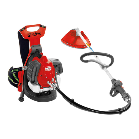
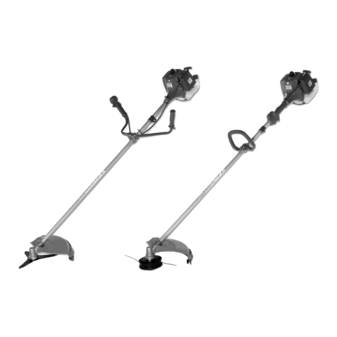
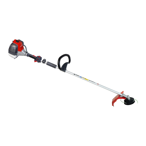
Efco ERGO 8465 Manual

8465 ERGO (45.7 cm3)- 8535 ERGO (52.5 cm3)
I
F
GB
D
E
NL
MANUALE USO E MANUTENZIONE
MANUEL D'UTILISATION ET D'ENTRETIEN
OPERATOR'S INSTRUCTION BOOK
BEDIENUNGSANLEITUNG
MANUAL DE INSTRUCCIONES
GEBRUIKSAANWIJZING

106 dB(A)
114 dB(A)
107 dB(A)
115 dB(A)
LpA av
EN 11806 - EN 22868 LwA
2000/14/EC - EN ISO 3744 - EN 22868
PRESSIONE ACUSTICA
PRESSURE LEVEL
PRESSION ACOUSTIQUE
SCHALLDRUCK
PRESION ACUSTICA
GELUIDSDRUCK
LIVELLO DI VIBRAZIONE
VIBRATION LEVEL
NIVEAU DE VIBRATION
VIBRATIONSPEGEL
NIVEL DE VIBRACION
DE TRILLINGSINTENSITEIT
MODELLO
MODEL
MODELE
MODELLE
MODELO
I - Valori medi ponderati: 1/2 minimo, 1/2 pieno carico (testina) o 1/2 velocità max a vuoto
(disco).
GB - Weighted average values: 1/2 minimum rpm, 1/2 at full load (head) or 1/2 racing (blade).
F - Valeurs moyennes poundérés: 1/2 au ralenti, 1/2 pleine charge (tête) ou 1/2 vitesse en pointe
dans le vide (disque).
D - Mittelwerte: 1/2 Leerlauf, 1/2 voll beladen (faden) oder 1/2 max. Geschwindigkeit unbeladen
(schneid).
E - Valores medios ponderados: 1/2 mínimo, 1/2 plena carga (cabezal) y 1/2 velocidad máxima
en vacío (disco).
NL - Gewogen gemiddelde waarden: 1/2 minimum, 1/2 volle lading (draad) of 1/2 max. snelheid
leeg (maaiblad).
ATTENZIONE !!!
RISCHIO DI DANNO UDITIVO
NELLE NORMALI CONDIZIONI DI UTILIZZO, QUESTA MACCHINA PUO'
COMPORTARE, PER L'OPERATORE ADDETTO, UN LIVELLO DI ESPOSIZIONE
PERSONALE GIORNALIERO A RUMORE PARI O SUPERIORE A
85 dB (A)
ATENCIÓN !!!
RIESGO DE DAÑO AUDITIVO
EN NORMALES CONDICIONES DE UTILIZACIÓN, ESTA MAQUINA PUEDE
TOLERAR PARA EL OPERADOR ENCARGADO, UN NIVEL DE EXPOSICÍON
DIARIO A RUIDO EQUIVALENTE O SUPERIOR A
85 dB (A)
ATTENTION !!!
DANGER D’ATTEINTE A L’OUIE
L’OPERATEUR UTILISANT NORMALEMENT CETTE MACHINE
PEUTS S’EXPOSER QUOTIDIENNEMENT
A UN BRUIT EGAL OU DEPASSANT
85 dB (A)
LET OP !!!
HOORSCHADEGEFLUIT
IN ZIJN NORMAAL GEBRUIKSTOESTAND KAN DEZE MACHINE VOOR DE
BESTEMDE OPERATOR EEN DAGELIJKS PERSOONLIJK
LAWAAIBLOOTSTELLING MET ZICH MEEBRENGEN, DIE
OF MEER BEDRAAGT
85 dB (A)
WARNING !!!
RISK OF DAMAGING HEARING
IN NORMAL CONDITIONS OF USE, THIS MACHINE
MAY INVOLVE A DAILY LEVEL OF PERSONAL EXPOSURE TO NOISE
FOR THE OPERATOR EQUAL TO OR GREATER THAN
85 dB (A)
ACHTUNG !!!
HÖRSCHADEN - RISIKO
UNTER NORMALEN ANWENDUNGSBEDIGUNGEN
KANN DIESES GERÄT DIE BEDIENUNGSPERSON
EINEM TÄGLICHEN GERÄUSCHPEGEL VON
ODER MEHR AUSSETZEN
85 dB (A)
I
D
E
NL
INTRODUZIONE
Per un corretto impiego del decespugliatore e per evitare incidenti, non iniziate il
lavorosenza averlettoquesto manualeconlamassimaattenzione.Troveretesuquesto
manuale le spiegazioni di funzionamento dei vari componenti e le istruzioni per i
necessari controlli e per la manutenzione.
N.B. Le descrizioni e le illustrazioni contenute nel presente manuale si intendono
nonrigorosamenteimpegnative.LaDittasiriservaildirittodiapportareeventuali
modiche senza impegnarsi ad aggiornare di volta in volta questo manuale.
ENLEITUNG
Um richtig mit der Motorsense umgehen zu können und Unfälle zu vermeiden, lesen Sie
diese Bröschure vor Aufnahme der Arbeit gründlich durch. Im Suchverzeichnis nden Sie
die Angabe, auf welchen Seiten die Hinweise zur Arbeitsweise der unterschiedlichen Teile
und Erklärungen zu den anfallenden Wartungs- und Kontrollarbeiten zu nden sind.
N.B.:DieindieserBröschureenthaltenenBeschreibungenundAbbildungenverstehen
sichunverbindlich.DerHerstellerbehältsichdasRechtvor,dieEinzel-undZubehörteile
dieses Modells aus technischen oder absatz-bedingten Gründen zu ändern , ohne die
Angaben dieser Bröschure jedesmal zu berichtigen.
INTRODUCCION
Para una correcta utilizaciòn de la desbrozadora y para evitar incidentes, no empiece
a trabajar sin haber leido atentamente este manual. Ud. encontrarà las explicaciones
de funcionamiento de los diferentes componentes y las instrucciones para el control
y mantenimiento de la desbrozadora.
P.D. Las descripciones contenidas en el presente manual no se consideran
rigurosamenteobligatorias.Laempresasereservaelderechodeaportareventuales
modicaciones sin obligarse a poner al dìa este manual.
Lees eerstdezegebuiksaanwijzinggrondigdooralvorensmetdebosmaaiertegaanwerken.
Dit teneinde de bosmaaier op juiste wijze te gebruiken en ongelukken te voorkomen.
De inhoudsopgave laat zien waar u uitleg over de verschillende instructies omtrent de
afzondelijke delen en noodzakelijke controles en onderhoudsvoorschrien kunt vinden.
PS Illustratles en specicaties in deze gebruiksaanwijzing kunnen varlëren van land
tot and en kunnen worden gewijzigd, zonder bericht van de fabrikant.
INLEIDING
2
GB INTRODUCTION
Tocorrectlyusethebrushcutterandpreventaccidents,donotstartworkwithouthaving
rst carefully read this manual. You will nd explanations concerning the operation of
the various parts plus instructions for necessary checks and relative maintenance.
Note:Illustrationsand specicationsin this manualmayvaryaccordingtoCountry
requirements and are subject to change without notice by the manufacturer.
FINTRODUCTION
Pour un emploi correct de la débroussailleuse et pour éviter les accidents, ne pas
commencer le travail sans avoir d'abord lu attentivement le manuel. Vous trouverez
les descriptions du fonctionnement des divers composants et les instructions pour
les contrôles nécessaires et pour l'entretien.
N.B. Les descriptions et les illustrations contenues dans ce manuel n'engagent
pas rigoureusement le constructeur. La société se réserve le droit d'apporter
d'éventuelles modications sans devoir mettre à jour à chaque fois le manuel.
EN 11806 - EN 22867 - EN 12096
2.5 *
2.8 *
2.5 *
2.8 *
3.1 *
3.8 *
3.1 *
3.8 *
sx dx
LIVELLO POTENZA ACUSTICA GARANTITO
GUARANTEED SOUND POWER LEVEL
NIVEAU PUISSANCE ACOUSTIQUE ASSURÉ
GARANTIERTER AKUSTISCHER SCHALLEISTUNGSPEGEL
NIVEL POTENCIA ACÚSTICA GARANTIZADO
GARANDEERD ACOUSTISCH VERMOGENSNIVEAU
91 dB(A) *
100 dB(A) *
93 dB(A) *
101 dB(A) *
45.7 cm3
52.5 cm3
m/s 2
*

I
F
GB
D
E
NL
INDICE
INTRODUZIONE________________________ 2
NORME DI SICUREZZA _________________ 4
COMPONENTI DEL DECESPUGLIATORE___ 10
SIMBOLI E AVVERTENZE DI SICUREZZA___ 11
ASSEMBLAGGIO________________________ 12 -14
NORME DI LAVORO_____________________ 14
DISPOSITIVI DI TAGLIO CONSIGLIATI ____ 16
AVVIAMENTO _________________________ 18 -20
ARRESTO MOTORE ____________________ 22
OPERAZIONI PRELIMINARI _____________ 24
MANUTENZIONE______________________ 26 -28
RIMESSAGGIO ________________________ 30
TESTINA A FILI DI NYLON ______________ 32
DATI TECNICI_________________________ 2 -33
CERTIFICATO DI GARANZIA____________ 34
INDEX
INTRODUCTION _______________________ 2
NORMES DE SECURITE __________________ 5
COMPOSANT DE LA DEBROUSSAILLEUSE
___ 10
EXPLICATION DES SYMBOLES ET REGLES DE SECURITE______
11
ASSEMBLAGE __________________________ 12 -14
NORMES DE TRAVAIL ___________________ 14
DISPOSITIFS DE COUPE PRÉCONISÉS _____ 16
MISE EN ROUTE ________________________ 18 -20
ARRET DU MOTEUR ___________________ 22
PREPARATION ________________________ 24
ENTRETIEN___________________________ 26 -28
REMISSAGE ___________________________ 30
TETE A FILS DE NYLON ________________ 32
DONNEES TECHNIQUES _______________ 2 -33
CERTIFICAT DE GARANTIE _____________ 34
INDEX
INTRODUCTION _______________________ 2
SAFETY PRECAUTIONS__________________ 4
BRUSH CUTTER COMPONENTS __________ 10
EXPLANATION OF SYMBOLS AND SAFETY WARNINGS_______
11
ASSEMBLY _____________________________ 12 -14
WORK PRECAUTIONS___________________ 14
RECOMMENDED CUTTING DEVICES _____ 16
STARTING _____________________________ 18 -20
STOPPING THE ENGINE ________________ 22
PREPARING TO WORK
__________________________
24
MAINTENANCE _______________________ 26 -28
STORAGE_____________________________ 30
NYLON LINE HEAD ____________________ 32
TECHNICAL DATA_____________________ 2 -33
WARRANTY CERTIFICATE ______________ 34
INHALT
ENLEITUNG ___________________________ 2
SICHERHEITSVORKEHRUNG_____________ 6
BAUTEILE DER MOTORSENSE ____________ 10
ERLAUTERUNG DER SYMBOLE-UND SICHERHEITSHINWEISE
___
11
MONTAGE _____________________________ 13 -15
ARBEITSVORKEHRUNG _________________ 15
EMPFOHLENE SCHNEIDVORRICHTUNGEN
___ 17
STARTVORGANG _______________________ 19 -21
MOTOR ABSTELLEN ___________________ 23
VORBEREITUNGEN FÜR DIE ARBEIT
_______
25
INSTANDHALTUNG____________________ 27 -29
LANGERUNG _________________________ 31
2-FADEN NYLONKOPF _________________ 32
TECHNISCHE ANGABEN _______________ 2 -33
GARANTIEZERTIFIKAT_________________ 35
INDICE
INTRODUCCION _______________________ 2
NORMAS DE SEGURIDAD________________ 6
COMPONENTES DE LA DESBROZADORA __ 10
EXPLICACION SIMBOLOS Y ADVERTENCIAS DE SEGURIDAD
___
11
MONTAJE______________________________ 13 -15
NORMAS DE TRABAJO __________________ 15
DISPOSITIVOS DE CORTE ACONSEJADOS
_____ 17
PUESTA EN MARCHA ___________________ 19 -21
PARADA DEL MOTOR __________________ 23
PREPARATIVOS PARA USAR_____________ 25
MANTENIMIENTO_____________________ 27 -29
ALMACENAJE _________________________ 31
CABEZAL CON HILOS DE NYLON________ 32
DATOS TECNICOS _____________________ 2 -33
CERTIFICADO DE GARANTIA ___________ 35
INHOUD
INLEIDING ____________________________ 2
VEILIGHEIDSVOORSCHRIFTEN __________ 7
BOSMAAIER COMPONENTEN____________ 10
UITLEG VAN DE VEILIGHEIDSSYMBOLEN
__
11
MONTAGE _____________________________ 13 -15
ARBEIDSVOORSCHRIFTEN ______________ 15
AANBEVOLEN SNIJWERKTUIGEN ________ 17
STARTEN ______________________________ 19 -21
HET STOPPEN VAN DE MOTOR__________ 23
VOORBEREIDINGEN VOOR HET WERKEN
__ 25
ONDERHOUD _________________________ 27 -29
OPSLAG ______________________________ 31
NYLON DRAADKOP____________________ 32
TECHNISCHE GEGEVENS_______________ 2 -33
GARANTIE BEWIJS_____________________ 35
3

Italiano
NORME DI SICUREZZA
English
SAFETY PRECAUTIONS
1234
4
WARNING: e brush cutter, if properly used, is a
quick, confortable and ecient tool. So that your
work is always pleasant and safe, please respect the
following safety precautions scrupulously.
1 - Neverusethebrushcutterwhenyouaretiredorfatigued
or if you have taken alcohol, drugs or medication
(Fig. 1).
2 - Wear appropriate clothing and safety articles such as:
boots, heavy-duty trousers, gloves, protective eyewear,
ear protection and protective helmet (look pag. 8-9).
Use clothing which is close-tting but comfortable.
3 - Do not allow children to use the brush cutter.
4 - Do not allow other people to remain within 15 metres
during brush cutter use (Fig. 2).
5 - Before using the brush cutter, make sure that the blade
xing bolt is well-tightened.
6 - e brush cutter must be equipped with the cutting
accessories recommended by the manufacturer (look
pag. 16-17).
7 - Never use the brush cutter without the blade guard or
the head.
8 - Before starting the engine, make sure that the throttle
lever works freely.
9 - Before starting the engine, make sure that the blade
is free to move and is not in contact with any foreign
objects.
10 - Every now and then while working, stop the engine and
check the blade. Replace it at the rst sign of cracks or
breaks (Fig. 3).
11 - With the engine idling, the blade should not turn. If it
ATTENZIONE - Il decespugliatore, se ben usato, è
unostrumentodilavororapido,comodoedecace.
Perchèilvostrolavorosiasemprepiacevoleesicuro,
rispettare scrupolosamente le norme di sicurezza
qui riportate.
1 - Non usare il decespugliatore in condizioni di
aaticamento sico o sotto l'eetto di alcool, droghe o
farmaci (Fig.1).
2 - Indossare abiti adatti e articoli di sicurezza quali
stivali, pantaloni robusti, guanti, occhiali protettivi,
cua e casco antinfortunistico (v. pag. 8-9).
Usare vestiario aderente ma comodo.
3 - Non permettere ai ragazzi di usare un decespugliatore.
4 - Non permettere ad altre persone di restare nel raggio
di 15 metri durante l'uso del decespugliatore (Fig. 2).
5 - Primadiusareundecespugliatorevericarecheilbullone
ssaggio disco sia ben stretto.
6 - Ildecespugliatoredeveessereequipaggiatocongliattrezzi
da taglio consigliati dal costruttore (v. pag. 16-17).
7 - Non usare il decespugliatore senza la protezione del
disco o della testina.
8 - Prima di avviare il motore controllare che la leva
acceleratore funzioni liberamente.
9 - Primadiavviareilmotoreaccertarsicheildiscosialibero
di girare e non sia a contatto con corpi estranei.
10 - Durante il lavoro controllare spesso il disco fermando
il motore. Sostituire il disco appena appaiono crepe o
rotture (Fig. 3).
11 - Con motore al minimo il disco non deve girare. In caso
contrario regolare la vite del minimo.
12 - Trasportare il decespugliatore a motore fermo e con il
copridisco montato (Fig. 4).
13 - Lavorare assicurandosi di essere in posizione stabile e
sicura (Fig. 5).
14 - Avviare il decespugliatore solo in luoghi ben ventilati.
15 - Con motore in moto non fare alcuna manutenzione e
non toccare il disco.
16 - Riempire il serbatoio lontano da fonti di calore e a
motore fermo (Fig. 6). Non fumare durante il riforni-
mento (Fig. 6).
17 - Non togliere il tappo del serbatoio con motore in
moto.
18 - Fare attenzione a non rovesciare miscela per terra o sul
motore.
19 - Seduranteilrifornimentoilcarburantefuoriesce,spostare
il decespugliatore prima di fare l'avviamento (Fig. 7).
2 0 - N o n u s a r e c a r b u r a n t e ( m i s c e l a ) p e r o p e r a z i o n i
di pulizia.
21 - Non controllare la scintilla della candela vicino al foro
del cilindro.
22 - Non lavorare con una marmitta danneggiata.
23 - Mantenere sempre pulite e asciutte le impugnature da
olio o carburante (Fig. 8).
24 - Conservare il decespugliatore in luogo asciutto, lontano
da fonti di calore e sollevato dal suolo.
25 - Non avviare il motore senza il braccio montato.
26 - Non tagliare troppo vicini al terreno per evitare sassi ed
altri oggetti.
27 - Controllare giornalmente il decespugliatore per
assicurarsi che ogni dispositivo, di sicurezza e non, sia
funzionante.
28 - Non eettuare operazioni o riparazioni che non siano
d i n o r m a l e m a n u t e n z i o n e . R i v o l g e r s i a d o f f i c i n e
autorizzate.

English Français
SAFETY PRECAUTIONS NORMES DE SECURITE
5 6 87
5
ATTENTION: Si vous utilisez correctement la
débroussailleusevousaurezuninstrumentdetravail
rapide,pratiqueetecace.Pourquevotretravailsoit
toujours agréable et sûr respectez scrupuleusement
les règles de sécurité reportées ci-dessous.
1 - N'utilisezpasladébroussailleusesivousêtesphysiquement
fatigué ou sous l'inuence de l'alcool, de drogues ou de
médicaments (Fig. 1).
2 - Portez des vêtements adéquats et sûrs comme par exemple
des bottes, un pantalon résistant, des gants, des lunettes
de protection, un casque antichoc (voir pag. 8-9). Utilisez
des vêtements adhérents mais commodes.
3 - Ne laissez pas les enfants utiliser la débroussailleuse.
4 - Veillez à ce que personne ne se trouve dans un rayon de
15 mètres quand la débroussailleuse est en marche (Fig.
2).
5 - Avant d'utiliser une débroussailleuse vériez si le boulon
de xage du disque est bien serré.
6 - La débroussailleuse doit être équipée des outils de coupe
conseillés par le fabricant (voir pag. 16-17).
7 - N'utilisez pas la débroussailleuse sans la protection du
disque.
8 - Avant de faire démarrer le moteur vériez si le levier de
l'accélérateur fonctionne librement.
9 - Avant de mettre le moteur en marche vériez si le disque
tourne bien librement et s'il n'est pas en contact avec des
corps étrangers.
10 - Pendant le travail contrôlez souvent le disque en arrêtant
le moteur. Changez de disque dès que vous remarquez des
ssures ou des cassures (Fig. 3).
11 - Ledisquenedoitpastournerquandlemoteurestauralenti.
S'il tourne réglez la vis du ralenti.
12 - Transportez la débroussailleuse quand le moteur est arrêté
does, regulate the idle adjustment screw.
12 - Carry the brush cutter with the engine o and with the
protective blade cover on (Fig. 4).
13 - Only work when you are in a stable and secure position
(Fig. 5).
14 - Start the brush cutter only in well-ventilated areas.
15 - Nevertouchthebladeorattemptanymaintenancework
while the engine is running.
16 - Fill the fuel tank with the engine o and away from heat
sources (Fig. 6). Do not smoke while lling the tank
(Fig. 6).
17 - Do not remove the fuel tank cap when the engine is
running.
18 - Be careful not to spill fuel on the ground or on the
engine.
19 - If fuel spills out during lling, move the brush cutter
away before starting the engine (Fig. 7).
20 - Do not use fuel mixture for cleaning operations.
21 - Do not check the spark plug spark near the cylinder
port.
22 - Never work with a damaged muer.
23 - Always keep the handles clean of oil and fuel (Fig. 8).
24 - Store the brush cutter in a dry place, away from heat
sources, and o the ground.
25 - Do not start the engine with the arm not mounted.
26 - In order to avoid hitting stones or other objects, do not
cut too close to the ground.
27 - Check the brush cutter daily to be sure that components
and safety devices are full functioning properly.
28 - Donotattempttocarryoutoperationsorrepairsthatare
not part of the normal maintenance. See the authorised
dealer.
et le couvre-disque monté (Fig. 4).
13 - Travaillezaprèsvousêtreassuréd'avoirunepositionstable
et sûre (Fig. 5).
14 - Faites démarrer la débroussailleuse uniquement dans des
endroits bien aérés.
15 - Quand le moteur tourne n'eectuez aucun entretien et ne
touchez pas au disque.
16 - Remplissez le réservoir loin des sources de chaleur et
quand le moteur et arrêté (Fig. 6). Ne fumez pas pendant
le ravitaillement (Fig. 6).
17 - N'enlevez pas le bouchon du réservoir si le moteur est en
marche.
18 - Faites attention à ne pas renverser le mélange par terre ou
sur le moteur.
19 - Sipendantle ravitaillementle carburantdéborde,déplacez
la débroussailleuse avant de la mettre en marche (Fig. 7).
20 - N'utilisez pas de carburant (mélange) pour les opérations
de nettoyage.
21 - Ne contrôlez pas l'étincelle de la bougie près du trou du
cylindre.
22 - Ne travaillez pas avec un pot d'échappement abîmé.
23 - Veillez à ce que les poignées soient toujours propres et
sèches, sans huile ni carburant (Fig. 8).
24 - Conservez la débroussailleuse dans un endroit sec, loin
des sources de chaleur, soulevée du sol.
25 - Ne faites pas démarrer le moteur sans que le bras soit
monté.
26 - Ne coupez pas trop près du terrain, vous éviterez ainsi les
cailloux et autre objets.
27 - Contrôleztouslesjoursladébroussailleuseetassurez-vous
que tous les dispositifs, de sécurité et autres, fonctionnent
bien.
28 - N'eectuez pas d'opérations ou de réparations qui ne
soient pas d'entretien normal. Adressez-vous plutôt à des
ateliers autorisés.

6
Italiano FrançaisEnglish
Deutsch
SICHERHEITSVORKEHRUNG
Español
NORMAS DE SEGURIDAD
1 2 43
ACHTUNG: Bei richtiger Anwendung ist die Motorsense
ein schnelles, bequemes und wirkungsvolles Arbeitsgerät
Damit Sie immer sicher und komfortabel arbeiten
können, beachten Sie bitte unbedingt die folgenden
Sicherheitsvorschrien.
1 - MotorsensenuringesundemundausgeruhtenZustandgebrauchen
nichtunterdemEinußvonAlkohol,DrogenoderMedicamenten
(Abb. 1).
2 - Stets geeignete Schutzkleidung sowie rutschfestes Schuhwerk,
Handschuhe, Lärmschutz, Schutzbrille und Helm tragen. Die
Kleidung soll anliegend aber bequem sein (Siehe Seite 8-9).
3 - Kinder in sicherer Entfernung halten.
4 - Beim Starten und beim Gebrauch der Motorsense dürfen sich
im Umkreis von mind. 15 m. des Arbeitsbereichs keine Personen
oder Tiere aualten (Abb. 2).
5 - VorjedemGebrauchdieFixierungsschraubedesSchneidwerkzeugs
auf festen Sitz überprüfen.
6 - Nur Schneidwerkzenge und Ersatzteile verwenden, die vom
Hersteller ausdrücklich empfohlen werden (Siehe Seite 16-17).
7 - Die Motorsense nur mit vorgesehener Schneidschutzvorrichtung
gebrauchen.SchultergurtemüssenvorArbeitsbeginnentsprechend
der Körpergrösse eingestellt werden.
8 - Vor dem Startvorgang Gashebel auf saubere Funktion
überprüfen.
Beim Loslassen muß der Gashebel selbsttätig in Nullstellung
zurückgehen.
9 - Vor dem Startvorgang darauf achten, daß das Schneidwerkzeug
freidrehenkannundmitkeinenHindernissenoderGegenständen
in Berührung kommt.
10 - VorundinregelmäßigkurzenAbständenwährenddesBetriebsist
dasSchneidwerkzeug-bei abgestelltemMotor-zuüberprüfen.Bei
Brüchen oder Rissbildungen ist das Schneidblatt bei abgestelltem
Motor (Montageanleitung beachten) auszuwechseln (Abb. 3).
11 - Im Leerlauf darf das Schneidwerkzeug nicht mitdrehen Sollte dies
derFall sein,muss dieLeerlauf-Stellschraube T eingestelltwerden
ATENCION: La máquina desbrozadora, si se usa
bien es un instrumento de trabajo rápido, cómodo
y ecaz. Para que su trabajo sea siempre placentero
y seguro, respete escrupulosamente las normas de
seguridad indicadas a continuación.
1 - No use nunca la desbrozadora cuando esté físicamente
cansado o se encuentre bajo ed efecto de alcohol, drogas
o medicación (Fig. 1).
2 - Use ropa apta y articulos de seguridad como botas,
pantalones resistentes,guantes,gafasycasco deprotección
(vea pág. 8-9). No use ropa demasiado suelta, más bien
adherente, pero cómoda.
3 - No permita que los niños usen la desbrozadora.
4 - No permita que otras personas permanezcan en el radio de
acción de 15 metros mientras está usando la desbrozadora
(Fig. 2).
5 - Antes de emplear la desbrozadora controle que el perno
de jación del disco esté bien apretado.
6 - La desbrozadora tiene que estar equipada con las
herramientas de corte recomendadas por el constructor
(vea pág. 16-17).
7 - No use nunca la desbrozadora sin la protección del disco
o del cabezal.
8 - Antes de poner en marcha el motor controle que la palanca
del acelerador funcione libremente.
9 - Antes de poner en marcha el motor controle que el disco
gire libremente y que no esté en contacto con cuerpos
extraños.
10 - Durante el trabajo controle a menudo el disco y para ello
pare el motor. Cambie el disco en cuanto aparezcan grietas
o roturas (Fig. 3).
(siehe Abschnitt "Vergaser")
12 - Die Motorsense nur mit abgestelltem Motor und mit montierter
Schneidschutzvorrichtung transportieren (Abb. 4).
13 - Beim Arbeiten ist auf einen sicheren Stand zu achten (Abb. 5).
14 - DieMotorsensedarfnichtingeschlossenenRäumen(ohneLüung)
gestartet oder betrieben werden.
15 - Wartungs- und Reinigungsarbeiten dürfen nur bei abgestelltem
Motor vorgenommen werden (ausgenommen Vergaser- und
Leerlaufeinstellung), Zündkerzenstecker vorher abziehen.
16 - Nachfüllen von Krasto nur bei abgestelltem Motor und fern
von oenem Feuer, dabei nicht rauchen (Abb. 6).
17 - Den Tankdeckel nicht bei laufendem oder nach warmem Motor
abnehmen.
18 - Darauf achten, daß kein Krasto auf den Boden oder auf den
Motor vergossen wird.
19 - Bei übergeschwapptem Krasto ist die Motorsense an einen
anderen Ort zu starten (Abb. 7).
20 - Reinigungsarbeiten nicht mit dem Krasto (Benzingemisch)
ausführen.
21 - Den Zündkerzenfunken nicht in unmittelbarer Nähe der
Zylinder-önung überprüfen.
22 - Die Motorsense nicht mit defektem Schalldämpfer betreiben.
23 - Die Grie immer sauber und frei von Öl bzw. Krasto halten
(Abb. 8).
24 - DieMotorsensenurantrockenenStellenlagern,desweiterennicht
an Boden auiegend und fern von oenem Feuer.
25 - Den Motor nicht starten, bevor Motor und Scha fertig montiert
sind.
26 - Nicht zu nah am Boden schneiden, um die Berührung von
Schneidwerkzeug mit Steinen oder Hindernissen zu vermeiden.
27 - Vor jedem Einsatzalle Vorrichtungen (auch die ander Motorsense
vorgesehenen Sicherheitsvorrichtungen) auf korrekte Funktion
überprüfen.
28 - Reparaturen oder Eingrie ausserhalb der normalen Wartung
müssenvomHändlerodervonderVertragswerkstattdurchgeführt
werden.

7
EspañolDeutsch Nederlands
Nederlands
VEILIGHEIDSVOORSCHRIFTEN
Español
NORMAS DE SEGURIDAD
56 8
1 - Gebruik de bosmaaier nooit als u vermoeid bent of wanneer
u alcohol, drugs of medicijnen hee gebruikt (Fig. 1).
2 - Draag altijd gepaste stevige kleding en veiligheidsuitrusting
(schoenen,eenlangebroek,handschoenen,oor-,oogbeschermig
eneenhelm)(ziepag.8-9).Dekledingmoetaangenaamzitten,
maar mag niet te los worden gedragen.
3 - Laat nooit een kind met de bosmaaier werken.
4 - De gebruiker moet erop letten, dat er zich in een straal van 15
meter van de in werking zijnde bosmaaier niemand anders
bevindt (Fig. 2).
5 - Voordat u de bosmaaier gebruikt dient u te controleren of de
schroef, die het maaiblad bevestigt, stevig vast zit.
6 - Gebruik nooit een ander snijwerktuig of -onderdeel, dat niet
expliciet is aanbevolen voor deze machine (zie pag. 16-17).
7 - De bosmaaier mag niet zonder maaibladbeveiliging worden
gebruikt.
8 - Voordat u de machine start, dient u te controleren of de
gashendel vrij functioneert.
9 - Voordat u de machine start, moet u ervoor zorgen dat het
maaiblad vrij kan draaien.
10 - Tijdens het werk moet u regelmatig het maaiblad controleren
(als de motor uit staat). Gebruik de bosmaaier nooit als het
maaibladkapotisofbreukenvertoont:udientdanhetmaaiblad
onmiddellijk te vervangen (Fig. 3).
11 - Het maaiblad mag niet draaien wanneer de motor stationair
draait.Alsdittochhetgevalis,dandientudestationairschroef
op de carburateur aan te passen (zie "het aanpassen van de
motor").
12 - Als u de bosmaaier vervoert, dan moet de motor zijn
LET OP: De bosmaaier, indien goed gebruikt, vormt een
snel, gemakkelijk en doeltreend werktuig. Opdat uw
werk altijd pretting en veiling is, de hier weergegeven
veiligheidenormen nauwkeurig in acht nemen.
uitgeschakeldenhetbladzijnbedektmetdemaaibladbeveiliging
(Fig. 4).
13 - Neemtijdenshetwerkenmetdebosmaaierenstabielehouding
aan (Fig. 5).
14 - Start en gebruik de machine nooit als deze in een gesloten
ruimte staat. Het inademen van uitlaatgassen kan namelijk
nadelige gevolgen voor de gezongheid hebben.
15 - Raak nimmer het maaiblad als de motor loopt en pleeg ook
geen onderhoud met draaieinde motor.
16 - Vul alleen brandstof bij als de machine uit staat en als er geen
open vuur in de buurt is (Fig. 6). Rook nooit tijdens het vullen
(Fig. 6).
17 - Verwijder nooit de dop van de brandstoank als de machine
nog loopt of warm is.
18 - Zorg ervoor dat u geen benzine over de machine of op de
grond morst.
19 - Als er brandstof gemorst wordt tijdens het vullen, dient u de
machine te verplaatsen om deze te starten (Fig. 7).
20 - Gebruik geen brandstof voor schoonmaakwerkzaamheden.
21 - Controleer nooit de bougie als u deze in de buurt van het
cilindergat houdt. Hierdoor vermijdt u dat brandstofdamp
die uit de cilinder komt spontaan ontbrandt.
22 - Gebruik de bosmaaier nooit als de uitlaat kapot is.
23 - Houd de handgrepen vrij van olie of brandstof (Fig. 8).
24 - Bewaardebosmaaieropeen,drogeplaats,vrijvanhittebronnen
en vrij van de grond.
25 - U mag de motor nooit starten zonder transmissiesteel.
26 - Maai niet te dicht bij de grond teneinde het raken van stenen
of andere objecten te vermijden.
27 - Controleer de bosmaaier dagelijks om er zeker van te zijn dat
alles juist functioneert en dat alle veiligheidsvoorzieningen
juist werken.
28 - Probeer geen reparaties te verrichten die buiten het normale
onderhoud vallen. Laat dit soort werkzaamheden over aan
uw dealer.
11 - Con el motor en ralenti el disco no tiene que girar. Si así
fuere regúlelo con el tornillo del mínimo.
12 - Transporte la desbrozadora con el motor parado y con el
cubre disco en su lugar (Fig. 4).
13 - Trabajesiempremanteniéndoseenposiciónestableysegura
(Fig. 5).
14 - Ponga en marcha la desbrozadora sólo en lugares bien
ventilados.
15 - No realice ninguna operación de mantenimiento con el
motor en marcha, ni tampoco toque el disco.
16 - Llene el depósito lejos de fuentes de calor y con el motor
parado (Fig. 6). No fume durante esta operación (Fig. 6).
17 - No quite el tapón del depósito con el motor en marcha.
18 - Tenga cuidado de no verter la mezcla de combustible en el
suelo o sobre el motor.
19 - Si al llenar el depósito saliera combustible, cambie de lugar
la desbrozadora antes de hacerla arrancar (Fig. 7).
20 - No use combustible (mezcla) para la limpieza.
21 - No controle la chispa de la bujia cerca de su alojamiento.
22 - No trabaje con el silenciador estropeado.
23 - Mantenga siempre secas y limpias las empuñaduras, sin
aceite ni combustible (Fig. 8).
24 - Conserve la desbrozadora en sitios secos, lejos de fuentes
de calor y posiblemente del suelo.
25 - No ponga en marcha el motor sin haber antes montado el
brazo.
26 - No corte demasiado cerca del terreno con el n de evitar
piedras u otros objetos.
27 - Controle diariamente la desbrozadora para asegurarse
que todos los dispositivos, de seguridad y no, funcionen
perfectamente.
28 - No efectúe Ud. mismo las operaciones que no sean de
mantenimiento normal. Diríjase a talleres autorizados.
7

Italiano
ABBIGLIAMENTO PROTETTIVO DI SICUREZZA
Français
1 2 3
English
SAFETY PROTECTIVE CLOTHING
Quando si lavora con il decespugliatore usare sempre
un abbigliamento protettivo di sicurezza omologato.
L’uso dell’abbigliamento protettivo non elimina i rischi
di lesione, ma riduce gli eetti del danno in caso di
incidente. Fatevi consigliare dal vostro rivenditore di
ducia per la scelta dell’abbigliamento adeguato.
L’abbigliamento deve essere adatto e non d’impaccio.
Indossare un abito aderente protettivo. La giacca
(Fig.1) e la salopette (Fig.2) di protezione Efco sono
l’ideale. Non portare abiti, sciarpe, cravatte o monili
chepotrebberoimpigliarsinellasterpaglia.Raccoglierei
capellilunghie proteggerli (per esempiocon un foulard,
un berretto, un casco, ecc.)
Indossare scarpe di sicurezza munite di suole
antisdrucciolo e puntali d’acciaio (Fig.3).
Indossare gli occhiali o la visiera protettivi
(Fig.4-5)!
Applicareprotezionidairumori;peresempiolecue
(Fig.6)oitappi.L’usodelleprotezioniperl’uditorichiede
maggior attenzione e prudenza, perché la percezione
di segnali acustici di pericolo (grida, allarmi, ecc.) è
limitata.
Calzare guanti (Fig.7) che permettano il massimo
assorbimento delle vibrazione.
Efco ore una gamma completa di equipaggiamento
per la sicurezza.
While working with the brushcutter, always use safety
protective approved clothing. e use of protective
clothing does not eliminate injury risks, but reduces the
injury eects in case of accident. Consult your trusted
supplier to choose an adequate equipment.
e clothing must be proper and not an obstacle. Wear
adherent protective clothing. Efco protective jackets
(Fig.1) and dungarees (Fig.2) are ideal. Do not wear
clothes, scarfs, ties or bracelets that can stuck into twigs.
Tie up and protect long hair (example with foulards,
caps, helmets, etc.).
Safety shoes having skid-proof sole and anti-piercing
insert (Fig.3).
Wear protective goggles or face screens (Fig.4-5)!
Use protections against noises; for example noise
reduction ear guards (Fig.6) or earplugs. e use of
protections for the ear requests much more attention
and caution, because the perception of danger audio
signals (screamings, alarms, etc.) is limited.
Wear gloves (Fig.7) that permit the maximum
absorption of vibrations.
Efco oers a complete range of safety equipments.
8
VÊTEMENTS DE PROTECTION
Toujours porter des vêtements de protection homologués
pour utiliser une débroussailleuse. Le port de vêtements de
protection n'élimine pas les risques de blessure mais il peut
en réduire les eets en cas d'accident. Demandez conseil à
votre revendeur habituel pour choisir le vêtement qui répond
le mieux à vos exigences.
Assurez-vousquelevêtementchoisinegênepaslesmouvements.
Portez un vêtement de protection près du corps. La veste
(Fig.1) etlasalopette(Fig.2) de protectionEfcosontl’idéal.
Ne portez pas de vêtements, écharpes, cravates ou bijoux qui
risqueraientdes'accrocherdanslesbuissons.Nouezlescheveux
longs et protégez-les (par exemple avec un foulard, un béret,
un casque, etc...).
Portezdes chaussuresde protectionavecsemelles antiglisse
et pointes en acier (Fig. 3).
Portez des lunettes ou une visière de protection (Fig. 4-5)!
Utilisez des dispositifs protégeant contre les émissions
sonores;casque(Fig.6)ouboulesdanslesoreilles.Rappelez-
vous d'être extrémement prudents lorsque vous utilisez ce
genre de protection car la perception des signaux acoustiques
de danger (cris, alarmes, etc...) est réduite.
Portez des gants (Fig. 7) qui absorbent le plus possible les
vibrations.
Efco offre une gamme complète d'équipements de
sécurité.

Español
Deutsch
45 7
6
Nederlands
9
SICHERHEITS-/SCHUTZKLEIDUNG
Bei der Arbeit mit dem Freischneider muss der Bediener daher
immerzugelassene Sicherheits-/Schutzkleidung tragen.Durch
die Benutzung der Schutzkleidung wird die Verletzungsgefahr
zwar nicht beseitigt, aber die Auswirkungen des Schadens im
Falle eines Unfalls reduziert. Ihr Fachhändler berät Sie gern bei
der Wahl der richtigen Schutzkleidung.
Die Kleidung muss geeignet sein und darf die Arbeit nicht
behindern. Tragen Sie anliegende Schutzkleidung. Die Jacke
(Abb.1) und die Schutzlatzhose (Abb.2) von Efco sind ideal.
TragenSiekeineKleider,Schals,KrawattenoderSchmuckstücke,
die sich im Gestrüpp verfangen könnten. Binden Sie langes
Haar zusammen und schützen Sie es (zum Beispiel mit einem
Schal, einer Mütze, einem Helm usw.)
Tragen Sie Sicherheitsschuhe mit rutschfesten Sohlen und
Stahlkappen (Abb.3).
B e n u t z e n S i e d i e S c h u t z b r i l l e o d e r d a s S c h u t z v i s i e r
(Abb. 4-5)!
Benutzen Sie einen Gehörschutz; zum Beispiel den
GehörschutzmitBügel(Abb.6)oderdieGehörschutzstöpsel.
Die Verwendung eines Gehörschutzes erfordert erhöhte
Aufmerksamkeit und Vorsicht, denn die Wahrnehmung
akustischer Warnsignale (Rufe, Alarme usw.) wird dadurch
eingeschränkt.
Tragen Sie Handschuhe (Abb.7), mit denen die Vibrationen
maximal gedämp werden.
Efco bietet ein komplettes Sortiment von
Sicherheitsausrüstungen.
INDUMENTOS DE SEGURIDAD
Para trabajar con la desbrozadora, colocarse siempre
indumentos de seguridad homologados. El uso de
elementosdeseguridadnoeliminalosriesgosdelesiones
pero reduce los daños en caso de accidente. Consultar
con el vendedor de la máquina sobre los indumentos
adecuados.
La ropa debe ser cumplir su función de protección y
ser cómoda. Utilizar ropa adherente y protectora. La
chaqueta (Fig. 1) y el peto (Fig. 2) de protección Efco
sonideales.Nollevarropa,bufandas,corbatasoadornos
que puedan ser atrapados por la maleza. Recogerse el
cabello largo y cubrirse, por ejemplo con un pañuelo,
una gorra o un casco.
Utilizarzapatosdeseguridadconsuelaantideslizante
y punteras de acero (Fig. 3).
¡Utilizar siempre las gafas o la visera de protección!
(Fig. 4-5)
Emplearelementosdeproteccióncontraelruido,como
auriculares(Fig.6)otapones.Elusodelasprotecciones
para el oído exige mayor atención y prudencia porque
se reduce la percepción de las señales sonoras de peligro
(gritos, alarmas, etc.).
Ponerse guantes (Fig. 7) que absorban el máximo
posible las vibraciones.
Efco ofrece un equipamiento de seguridad
completo.
BESCHERMENDE VEILIGHEIDSKLEDING
Draag daarom bij het werken met de bosmaaier altijd
goedgekeurde beschermende veiligheidskleding. Het
gebruik van beschermende kleding vermindert niet de
risico's voor letsel, maar beperkt wel de gevolgen van
ongevallen. Vraag uw dealer om advies bij het kiezen
van de juiste kleding.
Dekledingmoetgoed zitten,en magde bewegingenniet
hinderen. Draag niet te wijde, beschermende kleding.
Hetbeschermendejack(Fig.1)endebroek(Fig.2)van
Efco zijn hiervoor ideaal. Draag geen kleding, dassen,
stropdassenofsieradendieindetakkenverstriktkunnen
raken.Langhaarmagnietlosgedragenworden,en moet
worden beschermd (bijvoorbeeld met een hoofddoek,
een muts, een helm, enz.).
Draag veiligheidsschoenenmet antislipzoolenstalen
punten (Fig. 3).
Draag een veiligheidsbril of een vizier (Fig. 4-5)!
Gebruik gehoorbeschermingen; bijvoorbeeld
oorkappen (Fig. 6) of oordoppen. Het gebruik van
gehoorbeschermingen vereist grotere aandacht en
voorzichtigheid,wantgeluidssignalendiewaarschuwen
voorgevaar(schreeuwen,alarmen,enz.)wordenminder
goed gehoord.
Draaghandschoenen(Fig.7)diedetrillingenoptimaal
absorberen.
Efco biedt een complete veiligheidsuitrusting.

10
I
1 - Impugnatura sgancio
rapido
2 - Interruttore di massa
3 - Protezione marmitta
4 - Cinghiaggio
5 - Filtro aria
6 - T a p p o s e r b a t o i o
carburante
7 - Serbatoio carburante
8 - Leva acceleratore
F
1 - Poignée à décrochage
rapide
2 - Interrupteur d'arrêt du
moteur
3 - Protection du pot
d'échappement
4 - Courroies
5 - Filtre à air
6 - Bouchon du réservoir de
carburant
COMPONENTI DEL DECESPUGLIATORE COMPOSANT DE LA DEBROUSSAILLEUSE
GB
1 - Handle quick realise
2 - On/o switch
3 - Muer guard
4 - Harness
5 - Air lter
6 - Fuel tank cap
7 - Fuel tank
8 - rottle lever
BRUSH CUTTER COMPONENTS DBAUTEILE DER MOTORSENSE
E
1 - Empuñadura de
desenganche rápido
2 - Interruptor de parada del
motor
3 - Protección del silenciador
4 - Correaje
5 - Filtro de aire
6 - Tapón depósito
combustible
7 - Depósito combustible
COMPONENTES DE LA DESBROZADORA
NL
1 - Handgreep met
snelontkoppeling
2 - Aaan/uitschakelaar
3 - Uitlaatklep
4 - Draagriem
5 - Luchtlter
6 - Brandstoankdop
7 - Brandstoank
8 - Gashendel
BOSMAAIER COMPONENTEN
1 - Gri der
Schnellausklinkung
2 - Ein- / Aus - Schalter
3 - Hitzeschutzgitter
4 - Schultergurte
5 - Lulter
6 - Krastoankdechel
7 - Krastoank
8 - Gashebel
9 - Impugnatura/Barriera di
sicurezza
10 - Tubo di trasmissione
11 - Protezione avvolgente di
sicurezza
12 - Disco/Testina a fili di
nylon
13 - Protezione acceleratore
14 - Trasmissione essibile
15 - Maniglia per trasporto
9 - Handle/Safety boom
10 - Sha arm
11 - Curved guard
12 - Blade/Nylon line head
13 - rottle guard
14 - Flexible drive
15 - Transport handle
7 - Réservoir de carburant
8 - Levier de l'accélérateur
9 - Poignée/Barrière de sécurité
10 - Tuyau de transmission
11 - Protection de sécurité
12 - Disque/Tête a ls de nylon
13 - Protection accélérateur
14 - Transmission exible
15 - Poignée de transport
9 - Handgri/Schutzstange
10 - Scha
11 -
Schneidschutzvorrichtung
12 - Schneid blatt/2-faden
Nylonkopf
13 - Gashebelschutz
14 - Flexibler Scha
15 - Tragegri
8 - Palanca del acelerador
9 - Empuñadura/Barra de
seguridad
10 - Tubo de transmisión
11 - Protección
12 - Disco/Cabezal con hilos de
nylon
13 - Protecciòn acelerador
14 - Transmisiòn exible
15 - Asa para el transporte
9 - Handgreep/
Veiligheidsbarrière
10 - Steel
11 - Veiligheidsbeschermkap
12 - Maaiblad/Nylon draadkop
13 - Koppelingsbeveiliging
14 - Snoeroverbrenging
15 - Handvat voor transport

I
GB
F
SPIEGAZIONE SIMBOLI E AVVERTENZE DI SICUREZZA
EXPLANATION OF SYMBOLS AND SAFETY WARNINGS
EXPLICATION DES SYMBOLES ET REGLES DE SECURITE
ERLAUTERUNG DER SYMBOLE-UND SICHERHEITSHINWEISE
EXPLICACION SIMBOLOS Y ADVERTENCIAS DE SEGURIDAD
UITLEG VAN DE VEILIGHEIDSSYMBOLEN
D
E
NL
- Portare calzature di protezione e guanti usando dischi metallici o di
plastica.
- Wear strong boots and gloves when cutting with metal or plastic blades.
- Porter chaussures de protection et gants quand on utilise disques métalliques
ou de plastique.
- Sicherheitsschuhe und -handschuhe mit Metall- oder Plastikscheiben
tragen.
- Utilizar calzado de seguridad y guantes cuando se utilizan discos metálicos
o de plástico.
- Draag beschermende schoenen en handschoenen wanneer u metalen of
kunststof schijven gebruikt.
-Leggere il libretto uso e manutenzione prima di utilizzare questa
macchina.
-Read operator's instruction book before operating this machine.
-Lire le manuel avant d'utiliser cette machine.
-Betriebsanleitung vor der Inbetriebsnahme lesen.
-Antes de utilisar esta maquina, leer el manual de instrucciones.
-Lees de gebruikshandleiding alvorens u met de machine gaat werken.
-Prestare attenzione al lancio di oggetti.
-Be aware that objects can be thrown.
-Prêter d’attention au lancement d’objets.
-Vorsicht, auf aufspritzende Steine usw. achten.
-¡Atención! Posible expulsión de objetos.
-Let op wegspringende voorwerpen.
-Tenere persone lontane 15 m.
-Keep bystanders away 15 m.
-Personne doit approcher à moins de 15 m.
-Keine andere Person soll sich im Umkreis von 15 m aualten.
-La gente a más de 15 m.
-Zorg ervoor dat er zich geen mensen binnen een straal van 15 m in
uw werkgebied bevinden.
-Indossare casco, occhiali e cue di protezione.
-Wear head, eye and ear protection.
-Vêtir casque, visière et protège-oreilles.
-Immer Helm, Schutzbrille und Geräuschschutz tragen.
-Llevar casco, gafas y auriculares de proteccion.
-Draag ogg, -oor-en hoofdbescherming.
11

12
Italiano FrançaisEnglish
ASSEMBLAGGIO ASSEMBLAGEASSEMBLY
MONTAGGIO PROTEZIONE SICUREZZA (Fig. 1A-B)
Fissare la protezione (A) al tubo di trasmissione tramite
le viti (B), in una posizione che permetta di lavorare in
sicurezza.
NOTA: utilizzare la protezione (C, Fig. 1A) solamente
con la testina a li di nylon. La protezione (C) deve essere
ssata con la vite (G) alla protezione (A).
Per i dischi da legno (22-60-80 denti) utilizzare sempre
l’apposita protezione di metallo (Fig. 1B).
MONTAGGIO DISCO (Fig. 2)
Svitare in senso orario il bullone (A); togliere la coppa (D)
e la angia inferiore (E).Montare il disco (R) sulla angia
superiore (F) assicurandosi del giusto senso di rotazione.
Montare la angia inferiore (E), la coppa (D) ed avvitare il
bullone (A) in senso antiorario.
Inserire il perno in dotazione (L) , nell'apposito foro per
bloccare il disco e permettere il serraggio del bullone
(A, Fig. 2) a 2.5 kgm (25 Nm).
ATTENZIONE! - In caso di trasporto o rimessaggio
del decespugliatore, montare la protezione del disco (M)
cod. 4196086 come indicato nelle Fig. 4-5.
MONTAGGIO TESTINA A FILI DI NYLON (Fig. 3)
Inserire la angia superiore (F). Inserire il perno fermo
testina nell'apposito foro (L) ed avvitare in senso antiorario
la testina (N) con la sola forza delle mani.
MONTAGE PROTECTION-SECURITE (Fig. 1A-B)
Fixer la protection (A) au tuyau de transmission à l'aide
des vis (B) en position telle à vous permettre de travailler
en toute sécurité.
NOTE:utiliserlaprotection(C,Fig.1A)seulementavecla
tête l nylon. Le protecteur (C) doit être xé sur le carter
de protection (A) au moyen de la vis (G).
Pour les disques à bois (22-60-80 dents) utiliser toujours la
protéction spéciale en métal (Fig. 1B).
MONTAGE DU DISQUE (Fig. 2)
Dévissez le boulon dans le sens des aiguilles d'une montre
(A); otez le carter (D) et la bride inférieure (E). Montez le
disque (R) sur la bride supérieure (F), en vériant le bon
sens de rotation. Montez la bride inférieure (E), le carter (D)
et vissez le boulon (A) dans le sens contraire des aiguilles
d'une montre.
Enlez le goujonen dotation(L) dansle trouapproprié pour
pouvoir bloquer le disque et serrer le boulon (A, Fig. 2) à
2.5 kgm (25 Nm).
ATTENTION! - En cas de transport ou de remisage de
ladébroussailleuse,monter lecarterdeprotectiondudisque
(M) p.n. 4196086 comme le montre les Fig. 4-5.
MONTAGE DE LA TETE AUX FILS DE NYLON (Fig. 3)
Enlezlabridesupérieure(F).Enlezlegoujonquivabloquer
la tête dans son orice (L) et vissez à la main, dans le sens
contraire des aiguilles d'une montre, la tête (N).
FITTING THE SAFETY GUARD (Fig. 1A-B)
Fit the blade guard (A) to the sha arm with screws in a
position allowing the operator to work safely (B).
NOTE: use the guard (C, Fig. 1A) only with nylon head.
Secure the guard (C) to the protection (A) by means of
the screw (G).
When using discs for wood (22-60-80 teeth), always set up
metal guard (see Fig. 1B).
FITTING THE DISK (Fig. 2)
Loosen the bolt (A) clockwise; remove cup (D) and lower
ange (E).
Fix the blade (R) onto the upper ange (F) making sure that
the rotation direction is correct.
Fix the lower ange (E), the cup (D) and tighten bolt (A)
anti-clockwise.
Put the pin provided (L) in the appropriate hole to block
the blade and allow the bolt (A, Fig. 2) to be tightened to
2.5 kgm (25 Nm).
WARNING! - Fit the disk protection (M) p.n. 4196086
as shown (Fig. 4-5) before transporting or storing the
brushcutter.
FITTING THE NYLON LINE HEAD (Fig. 3)
Put the upper (F) ange in place. Put the head xing
pin in the appropriate hole (L) and tighten the head (N)
anti-clockwise by hand.
3
21A 1B L

13
EspañolDeutsch Nederlands
MONTAJE MONTAGE
´MONTAJE DE LA PROTECCION DE SEGURIDAD
(Fig. 1A-B)
Fije la protección (A) al tubo de transmisión, por medio de
los tornillos (B) en una posición tal que permita trabajar
con seguridad.
NOTA: utilize el protector (C, Fig. 1 A) solamente con la
cabeza con hilo de nylon. La protección (C) debe jarse
con el tornillo (G) a la protección (A).
Cuando se emplean discos para madera (22-60-80 dientes),
siempre se debe utilizar la protección metálica especial
(Fig. 1B).
MONTAJE DEL DISCO (Fig. 2)
Destornille en sentido horario el perno (A); quite la copeta
(D) y la brida inferior (E). Monte el disco (R) sobre la brida
superior(F)ycontrolequeelsentidoderotaciónseacorrecto.
Monte la brida inferior (E), la copeta (D) y apriete el perno
(A) en sentido antihorario.
Indroduzcaelpernoendotación(L),eneloriciopredispuesto
para bloquear el disco y ajuste el tornillo (A, Fig. 2) a
2.5 kgm (25 Nm).
ATENCIÓN! - Para transportar o guardar la
desbrozadora,montelaproteccióndeldisco(M)p.n.4196086
como ilustran las Fig. 4-5.
MONTAJE DEL CABEZAL DE HILOS DE NYLON
(Fig. 3)
Introduzca la arandela superior (F). Ponga el perno que
bloquea el cabezal en el oricio correspondiente (L) y
atornille el cabezal (N) en sentido antihorario ajustándolo
con la sola fuerza de las manos.
MONTAGE VAN DE VEILIGHEIDSKAP (Fig. 1A-B)
Monteer de kunststof of stalen beschermkap (A) met de
bouten op zodanige wijze aan de steel dat deze een goede
bescherming biedt (B).
OPMERKING: Gebruik de extra beschermrand (C,
Fig. 1 A) alleen in combinatie met de nylon draadkop.
De beschermkap (C) moet met de schroef (G) op de
beschermkap (A) bevestigd worden.
Voor hout-zaagschijven (22-60-80 tanden) moet altijd de
speciale metalen bescherming worden gebruikt (Fig. 1B).
MONTAGE VAN HET MAAIBLAD (Fig. 2)
Draai de bout (linkse draad) (A) met de klok mee los en
verwijderdeksel(D)enonderring(E).Monteerhetmaaimes
(R)opdeborgring(F)waarbijueroplet,datdedraairichting
goed is en dat deze goed gepositioneerd is t.o.v. de houder.
Monteer de onderring (E), deksel (D) en schroeout (A)
tegen de wijzers van de klok in vast.
Steek de meegeleverde blokkeerpen (L) in het daarvoor
bestemdegatomhetmaaibladteblokkeren.Nnukanmenbout
(A, Fig. 2) op moment vastdraaien (2.5 kgm - 25 Nm).
LET OP! - Monteer bij transport of opslag de
beschermkap (M) p.n. 4196086 van de maaischijf op de
bosmaaier zoals op de Fig. 4-5 is weergegeven.
MONTAGE VAN DE NYLON DRAADKOP (Fig. 3)
Monteer de bovenring (F) op hun plaats op de transmissie.
Plaats de blokkeerpen in het gat (L) en schroef de draadkop
(N) handvast tegen de wijzers van de klok in.
MONTAGE DER MOTORSENSE
MONTAGE DER SCHNEIDSCHUTZVORRICHTUNG
(Abb. 1A-B)
Die kunststo- oder Stahlschutzvorrichtung (A) mittels
Schrauben (B) am Scha befestigen.
ANMERKUNG: Schutzeinsatz (C, Abb. 1A) nur mit
Nylonfedenkopf verwenden. Die Schutzverkleidung (C)
muss mit der Schraube (G) an der Schutzverkleidung (A)
befestigt werden.
Holzschneidblätter (22-60-80 Zähne) dürfen ausschlißlich
mit dem entsprechenden Metallschutz (Abb. 1B) eingesetzt
werden.
MONTAGE DES SCHNEIDBLATTS (Abb. 2)
Die Schraube (A) im Uhrzeigersinn lösen, Gleitteller (D)
und unteren Flansch (E) abnehmen. Das Schneidblatt
(R) am oberen Flansch (F) montieren dabei auf richtige
Drehrichtung sowie korrekten Sitz auf der Nabe achten.
UnterenFlansch(E)undGleitteller(D)montieren,Schraube
(A) entgegen Uhrzeigersinn eindrehen.
Um die Schraube (A) (2.5 kgm/25 Nm) festzuziehen
(Abb. 2), den bei liegenden Sti (L) in die vorgesehene
Bohrung einsetzen.
ACHTUNG! - Für den Transport und die Lagerung
desMotorsensenmussdieSchneideblatt-Schutzverkleidung
(M) p.n. 4196086 wie auf den Abb. 4-5 dargestellt montiert
werden.
MONTAGE DES NYLONFADENKOPFS (Abb. 3)
Den oberen Flansch (F) im vorgesehenen Nabensitz
einsetzen.DenArretierungsstiindievorgeseheneBohrung
(L) einsetzen und den Nylonfadenkopf (N) nur von Hand
entgegen Uhrzeigersinn festschrauben.
45

14
Italiano FrançaisEnglish
MOUNTING TRANSMISSION (Fig. 8-9)
Pull pin (A) and insert the end of exible pipe (B) into clutch
housing (C). Make sure the end of the exible coupling t. Insert
pin (A) into the end of the exible hole (A1, Fig. 8). Insert exible
(B)intotube (E) making surethatexibleshaend (B) is correctly
inserted into the rigid sha of transmission (Fig. 9). Fasten it with
screw (F) and screws (D).
Insert the rigid drive sha tube (E, Fig.10) into the handle (G) and
fasten it by screwing the ring nut. To disassemble it, it is necessary
to push the button (L, Fig.11) and rotate the ring nut (H) in the
opposite direction. Fasten cable tube to the exible pipe with the
two clips (N, Fig.13-14).
FITTING THE HANDLE (Figs. 12)
Fit the handle onto the sha arm and secure it using screws (A),
washers, and nuts. e handle position is calculated depending
on the requirements of the operator.
WARNING! - e handle must be xed between the two
notches (M, Fig.12) indicated on the drive sha tube.
WARNING:Makesurethatallcomponentsareconnected
properly and all screws tightened.
WORK PRECAUTIONS
WARNING! - Always follow the safety precautions. e
brush cutter must only be used to trim grass material. Do not
use the brush cutter as a lever to li, move or break objects,
nor lock it on xed supports. It is forbidden to apply tools or
applicationsthatarenottheonesindicatedbythemanufacturer
onto the brush cutter’s power take-o.
ASSEMBLAGGIO - NORME DI LAVORO ASSEMBLAGE - NORMES DE TRAVAILASSEMBLY - WORK PRECAUTIONS
MONTAGGIO TRASMISSIONE (Fig. 8-9)
Tirare il perno (A) ed inlare l'estremità del essibile (B) nella cua
frizione (C) assicurandosi che codolo e giunto siano ben incastrati.
Inlare il perno (A) nel foro (A1) del codolo terminale del essibile
(Fig.8). Inserireilessibile(B)neltubo(E)accertandosicheilterminale
dell'albero essibile (B) sia inserito correttamente nell'albero rigido
della trasmissione (Fig. 9). Fissarlo con la vite (F) e le viti (D).
Inserire il tubo di trasmissione rigido (E, Fig.10) nell’impugnatura
(G) e ssarlo avvitando la ghiera (H). Per lo smontaggio è necessario
premere il pulsante (L, Fig.11) e ruotare la ghiera (H) nella direzione
opposta.
Fissare con le due apposite clip (N, Fig.13-14) il tubo cavi al
essibile.
MONTAGGIO IMPUGNATURA (Fig. 12)
Montare l'impugnatura sul tubo di trasmissione e ssarla tramite viti
(A), rondelle e dadi. La posizione dell'impugnatura è registrabile in
funzione all'esigenza dell'operatore.
ATTENZIONE!– L’impugnatura deveesseressataall’interno
delle due tacche (M, Fig.12) indicate sul tubo di trasmissione.
ATTENZIONE: Assicurarsi che tutti i componenti del
decespugliatore siano ben collegati e le viti serrate.
NORME DI LAVORO
ATTENZIONE! - Seguire sempre le norme di sicurezza. Il
decespugliatore deve essere utilizzato solamente per tagliare erba
o piccoli arbusti. È proibito tagliare altri tipi di materiale. Non
utilizzare il decespugliatore come leva per sollevare, spostare o
spezzareoggetti,nébloccarlosusostegni ssi. È proibitoapplicare
alla presa di forza del decespugliatore utensili o applicazioni che
non siano quelli indicati dal costruttore.
MONTAGE DU TRANSMISSION (Fig. 8-9)
Tirer le tourillon (A) et enler l'extrémité du exible (B) dans le
carter d'embrayage (C) en s'assurant que l'embout du exible et la
bague d'accouplement soient encastrés. Enler le tourillon (A) dans
le trou de l'embout du exible (A1, Fig. 8). Insérer le exible (B) dans
la transmission (E); s'assurer que l'extrémité du exible (B) soit bien
monté dans la transmission (Fig. 9). Le xer à l’aide de la vis (F) et
la vis (D).
Installer le tuyau rigide de transmission (E, Fig. 10) dans la poignée
(G) et le xer en vissant la bague (H). Pour le démontage, appuyer
sur le bouton (L, Fig. 11) et tourner la bague (H) dans la direction
opposée.
Fixer le tuyau porte-câbles sur le exible à l’aide des deux clips
(N, Fig. 13-14).
MONTAGE DE LA POIGNEE (Fig. 12)
Montez la poignée sur le tuyau de transmission et xez-la avec les
vis (A), les rondelles et les écrous. La position de la poignée se règle
selon les exigences de l'opérateur.
ATTENTION! – Fixer la poignée à l’intérieur des deux crans
(M, Fig. 12) indiqués sur le tuyau de transmission.
ATTENTION: Veillez à ce que tous les composants soient
bien relié et les vis serrées.
NORMES DE TRAVAIL
ATTENTION! - Respectez toujours les normes de sécurité.
Le débroussailleuse ne doit être utilisé que pour tailler des herbe
oude petitsarbustes.Il est interditde tailler autre chose. N’utilisez
pas le comme levier pour lever, déplacer ou fendre des objets et ne
le bloquez pas sur des supports xes. Il est interdit d’appliquer à
la prise de force du débroussailleuse des outils ou des applications
autres que ceux qui sont indiqués par le constructeur.
8
9
10
11

15
EspañolDeutsch Nederlands
MONTAJE - NORMAS DE TRABAJO MONTAGE - ARBEIDSVOORSCHRIFTEN
MONTAJE DEL MOTOR (Fig. 8-9)
Tirar el perno (A), introducir el extremo del exible (B) en el carter
embrague (C) y asegurarse que el espigón y la junta estén encastrados.
Introducir el perno en el ojo del epigón terminal del exible (A1, Fig.
8). Introducir el exible (B) en el tubo (E) asegurándose que el espigón
y la junta de transmissión (B) estén bien encastrados (Fig. 9). Fíjelo con
el tornillo (F) y tornillo (D).
Inserte el tubo de transmisión rígido (E, Fig. 10) en la empuñadura (G) y
fíjelo con la tuerca (H). Para desmontarlo, presione el botón (L, Fig. 11)
y gire la tuerca (H) en el sentido opuesto.
Fije el tubo de los cables al exible con los dos clips (N, Fig. 13 y 14).
MONTAJE DE LA EMPUÑADURA (Fig. 12)
Monte la empuñadura en el eje de transmisión y jela mediante los
tornillos (A), las arandelas y las tuercas.
La posición de la empuñadura es regulable en función de las exigencias
del operador.
ATENCIÓN – La empuñadura debe jarse entre las dos marcas
(M, Fig. 12) realizadas en el tubo de transmisión.
ATENCIÓN:Asegúresequetodosloscomponentesseencuentren
bien conectados y los tornillos apretados.
NORMAS DE TRABAJO
ATENCION! - Respetar siempre las normas de seguridad.
La desbrozadora debe ser utilizada solamente para cortar césped o
pequeñosarbustos.Estáprohibidasuutilizaciónparacortarcualquier
otro tipo de material. No utilizar la desbrozadora como palanca
para levantar, desplazar o para romper objetos, ni bloquearlo sobre
sostenes jos. Está prohibida la aplicacíon a la toma de fuerza de la
desbrozadora de utensilios o accesorios que no sean los indicatos por
el fabricante.
MONTAGE VAN DE MOTOR (Fig. 8-9)
Aan pin (A) trekken en het uiteinde van het snoer (B) in de
koppelingscarter (C) steken en zich ervan overtuigen, dat het snoereind
en het verbindingsstuk goed in elkaar zitten. Pin (A) in het gat van het
eindstukvanhetsnoersteken(A1,Fig.8).Hetsnoer(B)inbuis(E)steken
en zich ervan overtuigen, dat het eindstuck van de beweeglijke as (B) op
de juiste manier in de vaste overdrachtsas zit (Fig. 9). Bevestig hem met
de schroef (F) en schroef (D).
Steek de steel (E, Fig. 10) in de handgreep (G) en bevestig hem door
de bevestigingsring (H) aan te draaien. Druk voor de demontage op
de knop
(L, Fig. 11) en draai de bevestigingsring (H) in de tegenovergestelde
richting.
Bevestig de kabelbuis met de twee clips (N, Fig. 13-14) aan de slang.
MONTAGE VAN DE HANDGREEP (Fig. 12)
Plaats de handgreep op de steel en vergrendel deze door schroeven (A),
ringenenmoerengelijkmatigenkruiselingsvasttedraaien.Dehandgreep
positie is berekend op normaal gebruiksgemak van de gebruiker.
LET OP! – De handgreep moet binnen de twee streepjes op de
steel (M, Fig. 12) worden bevestigd.
LETOP:Controleerofallecomponentengoedgemonteerd zijn
en dat alle schroeven goed vastgedraaid zijn.
ARBEIDSVOORSCHRIFTEN
LET OP! - Altijd de veiligheidsvoorsschrien volgen. De
bosmaaiermoet siechts gebruikt wordenvoor het knippen vangras en
kleine heesters. Het is verboden ieder ander materiaal te knippen. De
bosmaaiernietgebruikenomvoorwerpenoptelichten,teverplaatsen,
te versplinteren. Niet blokkeren op een vaste steun. Het is verboden
om aan het hoofdcontact van de bosmaaier andere hulpstukken te
verbinden als die door de fabrikant aangegeven worden.
MOTOR- UND SCHAFTMONTAGE (Abb. 8-9)
Den Zapfert (A) ziehen und das andere Ende des Schlauchs (B) in die
Kupplungshaube (C) einsetzen. Sich dabei vergewissern, dass End und
Verbindungsstüch gut eingerastet sind. Zapfen (A) in die Bohrung des
Endstückes des Schalauches ein Führen (A1, Abb. 8). Schlauch (B) in das
Rohr (E) einführen und dabej sicherstellen, daß die biegsame Welle (B)
fest in der festen Antriebswelle eingerastet ist (Abb. 9). Mit der Schraube
(F) und Schraube (D) befestigen.
Das Übertragungsrohr (E, Abb. 10) in den Gri (G) stecken und durch
Zudrehen der Überwurfmutter (H) befestigen. Zum Auseinanderbauen
die Taste (L, Abb. 11) drücken und die Überwurfmutter (H) in die
entgegengesetzte Richtung drehen.
Das Kabelrohr mit den zwei Clips (N, Abb. 13-14) an der biegsamen
Antriebswelle befestigen.
GRIFFMONTAGE (Abb. 12)
Den Griff auf den Schaft montieren und mittels Schrauben A,
Unterlegscheiben und Muttern gleichmässig und kreuzweise
festschrauben. Die Griposition ist entsprechend den Ansprüchen des
Bedieners verstellbar.
ACHTUNG! – Der Gri muss zwischen den zwei Markierungen
(M, Abb. 12) am Übertragungsrohr befestigt werden.
ACHTUNG: Beachten, daß alle Bauteile sauber angeschlossen
und die Schrauben festgezogen sind.
ARBEITSVORKEHRUNG
ACHTUNG! - Befolgen Sie immer die Sicherheitsvorkerungen.
Der Motorsense darf nur für den Schnitt von gras oder kleinen
Sträucherneingesetztwerden.Esistabsolutverboten,andereArtenvon
Materialienzuschneiden.BenutzenSiedenMotorsensenichtalsHebel
zum Anheben, Versetzen oder zum Zerkleinern von Gegenständen;
befestigen Sie ihn auch nicht an starren Halterungen. Es ist verboten,
amAntriebdesMotorsenseGeräteoderZusätzeanzubringen,dienicht
vom Hersteller für diesen Zweck ausdrücklich angegeben sind.
MONTAGE DER MOTORSENSE -ARBEITSVORKEHRUNG
12 13 14

16
Italiano FrançaisEnglish
DISPOSITIVI DI TAGLIO CONSIGLIATI DISPOSITIFS DE COUPE PRÉCONISÉSRECOMMENDED CUTTING DEVICES
1. Lama di nylon 4 denti – Ø 10”/255 mm
2. Lama di nylon 3 denti – Ø 10”/255 mm
5. Disco “Pro Trim Professional” 3 lame –
Ø 315 mm
7. Testina “Batti e vai” Ø 130 mm – 2 li nylon
Ø 3 mm
9. Testina“Multiline”Ø3.15”/80mm–8liquadrati
lato 3.5 mm
10. Testina “Multiline” Ø 5.2”/137 mm – 8 fili
quadrati lato 3 mm
11. Lama per erba Ø 12”/305 mm, spessore
2.5 mm
12. Disco 3 denti Ø 10”/255 mm, spessore 1.4 mm
13. Disco 3 lame sse Ø 10”/255 mm, spessore
1.4 mm
14. Disco 3 denti Ø 10”/255 mm, spessore 1.8 mm
15. Disco 3 denti Ø 12”/305 mm, spessore 2.4 mm
17. Disco 4 denti Ø 10”/255 mm, spessore 1.4 mm
19. Disco 8 denti Ø 10”/255 mm, spessore 1.4 mm
22. Disco 60 denti Ø 10”/255 mm, spessore
1.8 mm
24. Disco 80 denti Ø 10”/255 mm, spessore 1.4 mm
ATTENZIONE - L’utilizzo di dispositivi di
taglio non approvati dal costruttore può condurre a
situazioni di pericolo.
1. Lame nylon 4 dents – Ø 10”/255 mm
2. Lame nylon 3 dents – Ø 10”/255 mm
5. Disque “Pro Trim Professional” 3 lames –
Ø 315 mm
7. Tête “Tap and go” Ø 130 mm – 2 ls nylon
Ø 3 mm
9. Tête “Multiline” Ø 3.15”/80 mm – 8 ls carrés côté
3.5 mm
10. Tête “Multiline” Ø 5.2”/137 mm – 8 ls carrés côté
3 mm
11. Lames pour l’herbe Ø 12”/305 mm, épaisseur
2.5 mm
12. Disque 3 dents Ø 10”/255 mm, épaisseur 1.4 mm
13. Disque 3 lame xes Ø 10”/255 mm, épaisseur
1.4 mm
14. Disque 3 dents Ø 10”/255 mm, épaisseur 1.8 mm
15. Disque 3 dents Ø 12”/305 mm, épaisseur 2.4 mm
17. Disque 4 dents Ø 10”/255 mm, épaisseur 1.4 mm
19. Disque 8 dents Ø 10”/255 mm, épaisseur 1.4 mm
22. Disque 60 dents Ø 10”/255 mm, épaisseur
1.8 mm
24. Disque 80 dents Ø 10”/255 mm, épaisseur
1.4 mm
ATTENTION - L’utilisation d’accessoires
de coupe non approuvé par le constructeur peut
entraîner des situations à risque.
1. 4-tooth nylon blade – Ø 10”/255 mm
2. 3-tooth nylon blade – Ø 10”/255 mm
5. “Pro Trim Professional” disc 3-blade – Ø 315
mm
7. “Tap and go” head Ø 130 mm – 2 nylon lines
Ø 3 mm
9. “Multiline” head Ø 3.15”/80 mm – 8 square lines
3.5 mm sides
10. “Multiline” head Ø 5.2”/137 mm – 8 square lines
3 mm sides
11. Grass blade Ø 12”/305 mm, 2.5 mm thickness
12. 3-tooth disk Ø 10”/255 mm, 1.4 mm thickness
13. 3-xed teeth blade Ø 10”/255 mm, 1.4 mm
thickness
14. 3-tooth disk Ø 10”/255 mm, 1.8 mm thickness
15. 3-tooth disk Ø 12”/305 mm, 2.4 mm thickness
17. 4-tooth disk Ø 10”/255 mm, 1.4 mm thickness
19. 8-tooth disk Ø 10”/255 mm, 1.4 mm thickness
22. 60-tooth disk Ø 10”/255 mm, 1.8 mm
thickness
24. 80-tooth disk Ø 10”/255 mm, 1.4 mm thickness
WARNING – e use of cutting devices not
authorised by the manufacturer can generate safety
risks.
9.
p.n. 4180058

17
EspañolDeutsch Nederlands
DISPOSITIVOS DE CORTE ACONSEJADOS AANBEVOLEN SNIJWERKTUIGEN
1. Hoja de nailon 4 dientes – Ø 10”/255 mm
2. Hoja de nailon 3 dientes – Ø 10”/2550 mm
5. Disco “Pro Trim Professional” 3 hojas –
Ø 315 mm
7. Cabezal “Tap and go” Ø 130 mm – 2 hilos de nailon
Ø 3 mm
9. Cabezal “Multiline” Ø 3,15”/80 mm – 8 hilos
cuadrados 3.5 mm de lado
10. Cabezal “Multiline” Ø 5,2”/137 mm – 8 hilos
cuadrados 3 mm de lado
11. Hoja para Hierba Ø 12”/305 mm, grosor 2.5 mm
12. Disco 3 dientes Ø 10”/255 mm, grosor 1.4 mm
13. Disco 3 hojas jas Ø 10”/255 mm, grosor 1.4
mm
14. Disco 3 dientes Ø 10”/255 mm, grosor 1.8 mm
15. Disco 3 dientes Ø 12”/305 mm, grosor 2.4 mm
17. Disco 4 dientes Ø 10”/255 mm, grosor 1.4 mm
19. Disco 8 dientes Ø 10”/255 mm, grosor 1.4 mm
22. Disco 60 dientes Ø 10”/255 mm, grosor 1.8 mm
24. Disco 80 dientes Ø 10”/255 mm, grosor 1.4 mm
ATENCIÓN – El uso de dispositivos de corte
no aprobados por el fabricante puede provocar
situaciones de peligro.
1. Nylon maaiblad 4 tanden – Ø 10”/255 mm
2. Nylon maaiblad 3 tanden – Ø 10”/255 mm
5. Schijf “Pro Trim Professional” 3 maaibladen –
Ø 315 mm
7. Kop “Tap and go” Ø 130 mm – 2 nylon draden
Ø 3 mm
9. Kop“Multiline”Ø3.15”/80mm–8vierkantedraden
zijkant 3.5 mm
10. Kop“Multiline”Ø5.2”/137mm–8vierkantedraden
zijkant 3 mm
11. Gras maaiblad Ø 12”/305 mm, dikte 2,5 mm
12. Schijf 3 tanden Ø 10”/255 mm, dikte 1.4 mm
13. Schijf 3 vast maaiblad Ø 10”/255 mm, dikte
1.4 mm
14. Schijf 3 tanden Ø 10”/255 mm, dikte 1.8 mm
15. Schijf 3 tanden Ø 12”/305 mm, dikte 2.4 mm
17. Schijf 4 tanden Ø 10”/255 mm, dikte 1.4 mm
19. Schijf 8 tanden Ø 10”/255 mm, dikte 1.4 mm
22. Schijf 60 tanden Ø 10”/255 mm, dikte 1.8 mm
24. Schijf 80 tanden Ø 10”/255 mm, dikte 1.4 mm
LETOP-Hetgebruikvansnijwerktuigendieniet
goedgekeurd zijn door de fabrikant kan gevaarlijke
situaties tot gevolg hebben.
EMPFOHLENE SCHNEIDVORRICHTUNGEN
1. Nylonschneideblatt mit 4 Zähnen – Ø 10”/255 mm
2. Nylonschneideblatt mit 3 Zähnen – Ø 10”/255 mm
5. Schneideblatt “Pro Trim Professional” mit 3 Klingen –
Ø 315 mm
7. Schneidkopf “Tap and go” Ø 130 mm – 2 Nylonfäden
Ø 3 mm
9. Schneidkopf“Multiline”Ø3.15”/80mm–8quadratische
Nylonfäden, Seitenlänge 3.5 mm
10. Schneidkopf“Multiline”Ø5.2”/137mm–8quadratische
Nylonfäden, Seitenlänge 3 mm
11. Klingen für Gras Ø 12”/305 mm, Dicke 2.5 mm
12. Schneideblatt mit 3 Zähnen Ø 10”/255 mm, Dicke
1.4 mm
13. Schneideblattmit3festenKlingenØ10”/255mm,Dicke
1.4 mm
14. Schneideblatt mit 3 Zähnen Ø 10”/255 mm, Dicke
1.8 mm
15. Schneideblatt mit 3 Zähnen Ø 12”/305 mm, Dicke
2.4 mm
17. Schneideblatt mit 4 Zähnen Ø 10”/255 mm, Dicke
1.4 mm
19. Schneideblatt mit 8 Zähnen Ø 10”/255 mm, Dicke
1.4 mm
22. Schneideblatt mit 60 Zähnen Ø 10”/255 mm, Dicke
1.8 mm
24. Schneideblatt mit 80 Zähnen Ø 10”/255 mm, Dicke
1.4 mm
AC H T U N G - D i e Ve r w e n d u n g v o n
Schneidvorrichtungen,dienichtvomHerstellerzugelassen
sind, kann Gefahrensituationen zur Folge haben.

18
Italiano FrançaisEnglish
OLIO - HUILE - OIL
ÖL - ACEITE - OLIE
2%-50 : 1 4%-25 : 1
1
5
10
15
20
25
BENZINA - ESSENCE
GASOLINE - BENZIN
GASOLINA - BENZINE
AVVIAMENTO MISE EN ROUTESTARTING
MISCELA CARBURANTE (Fig. 16-17)
Usare carburante (miscela olio/benzina) al 4% (25:1).
Con olio PROSINT 2 eEUROSINT 2 EFCO usare miscela
al 2% (50:1).
ATTENZIONE:Imotori2tempisonodotatidipotenza
specica elevata, consigliamo quindi l’uso di benzine senza
piombo di marca conosciuta, con un numero di ottani non
inferiore ai 90. LEGGI LOCALI REGOLANO IL TIPO DI
BENZINA DA UTILIZZARE (CON O SENZA PIOMBO).
é OBBLIGATORIO RISPETTARLE!
- Tenerelabenzina,l’olioelamiscelaincontenitoriomologati
(Fig.18).
- Nella preparazione della miscela usare solo olio specico
per motori 2 tempi (Fig.19).
- Agitare la tanica della miscela prima di procedere al
rifornimento (Fig. 20).
- Eseguireilrifornimentocarburantesempreamotorespento
e lontano da amme (Fig. 21).
- Prima di svitare il tappo del serbatoio posizionare il
decespugliatoresudi unasupercie pianaesolidainmodo
che non possa rovesciarsi. Aprire con cautela il tappo per
scaricare lentamente l’eccesso di pressione e per evitare
che il carburante schizzi fuori.
- Prepararesololamiscelanecessariaall’uso;nonlasciarlanel
serbatoio o tanica per molto tempo. Si consiglia l’utilizzo
di additivo ADDITIX 2000 della Emak cod. 001000972
(Fig. 22), per conservare la miscela per un periodo di un
anno.
ATTENZIONE – Inalare i gas di scarico è nocivo per
la salute.
MELANGE CARBURANT (Fig. 16-17)
Utilisez du carburant (mélange huile/essence) à 4% (25:1).
Avec l'huile PROSINT 2 et EUROSINT 2 EFCO utilisez mèlange
à 2% (50:1).
ATTENTION:- Les moteursdeux-tempsont unepuissance
spéciqueélevée.Nouspréconisons,dès lors,d’utiliserdel’essence
sans plomb de marque connue, avec un taux d’octane non
inférieur à 90. LES LOIS LOCALES RÉGLEMENTENT LE
TYPE D'ESSENCE À UTILISER (AVEC OU SANS PLOMB).
LES RESPECTER IMPÉRATIVEMENT!
- L’essence, l’huile et le mélange devront être conservées dans des
récipients homologués (Fig.18).
- N’utiliser pour le mélange que de l’huile spéciquement
appropriée pour les moteurs deux-temps (Fig.19).
- Agiter le bidon contenant le mélange avant de le verser dans le
réservoir (Fig.20).
- N’eectuer le réapprovisionnement en carburant qu’avec
le moteur éteint et à distance sûre de tout foyer ou amme
(Fig.21).
- Avant de dévisser le bouchon du réservoir, placer le
debroussailleuse sur une surface plane et stable pour qu’il ne
puisse pas se renverser. Ouvrir avec précaution le bouchon an
de laisser échapper lentement l’excès de pression et d’éviter les
giclées de carburant.
- Ne pas préparer plus de mélange que la quantité requise pour
l’utilisation; ne pas laisser le mélange dans le réservoir ou dans
le bidon pendant trop de temps. Il est recommandé d’utiliser
un additif tel que l’ ADDITIX 2000 de la marque Emak code
001000972 (Fig.22), lorsqu’on veut garder le mélange pendant
une période d’un an.
ATTENTION – L’inhalation des gaz d’échappement est
nuisible à la santé.
FUEL MIXTURE (Fig. 16-17)
Use a 4% (25:1) oil/gasoline mixture.
With PROSINT 2 and EUROSINT 2 EFCO oil use a 2%
(50:1) mixture.
WARNING: – e 2-stroke engines have high power
ratings,wethereforerecommendthe use oflead-freepetrol
of known brand, with an octane rating no lower than 90.
THE TYPE OF GASOLINE TO BE USED (LEADED OR
UNLEADED) IS REGULATED BY LOCAL LAWS. IT
MUST BE FOLLOWED!
- Store petrol, oil and the mixture in approved containers
(Fig.18).
- To prepare the mixture, use only specic oil for 2-stroke
engines (Fig.19).
- Stir the mixture well before refuelling (Fig.20).
- Always refuel with the engine switched o and away from
naked ames (Fig.21).
- Before unscrewing the fuel tank cap, position the brush
cutter on a solid, at surface so that it cannot fall over.
Open the cap carefully to allow any excess pressure to
escape slowly without the fuel spraying out.
- Prepare only the quantity of mixture required for
immediateuse; do notleavefuel in thetank or a container
for a long time. We recommend the use of the additive
Emak ADDITIX 2000 code 001000972 (Fig. 22) if the
mixture is to be stored for up to a year.
WARNING – Inhalation of exhaust gases can be
harmful to your health.
17 18 19
l
0,04 (40)
0,20 (200)
0,40 (400)
0,60 (600)
0,80 (800)
1,00 (1000)
0,02 (20)
0,10 (100)
0,20 (200)
0,30 (300)
0,40 (400)
0,50 (500)
l (cm3) l (cm3)
17
16

19
EspañolDeutsch Nederlands
PUESTA EN MARCHA STARTEN
MEZCLA COMBUSTIBLE (Fig. 16-17)
Emplee combustible (mezcla de gasolina/aceite) al 4%
(25:1).
Con aceite PROSINT 2 yEUROSINT 2 EFCO usar mezcla
al 2% (50:1).
ATENCIÓN: - Los motores de dos tiempos tienen
una potencia especíca elevada, por lo cual se aconseja el
uso de gasolina sin plomo de marca conocida, con un
número de octanos no inferior a 90. LAS LEYES LOCALES
REGLAMENTAN EL TIPO DE GASOLINA QUE DEBE
UTILIZARSE (CON O SIN PLOMO). ES OBLIGATORIO
RESPETARLAS.
- Conserve la gasolina, el aceite y la mezcla en recipientes
homologados (Fig.18).
- En la preparación de la mezcla, utilice sólo aceite especíco
para motores de dos tiempos (Fig.19).
- Agite el bidón de la mezcla antes de verterla (Fig.20).
- Cargue siempre el combustible con el motor apagado y lejos
de cualquier llama (Fig.21).
- Antes de desenroscar el tapón del depósito, apoye la
desbrozadoraenunasuperciellanayrmedemodo queno
se tumbe. Abra con cuidado el tapón para aliviar lentamente
el exceso de presión y evitar que el combustible salpique.
- Prepare sólo la mezcla necesaria para el uso; no la deje en el
depósito o en el bidón durante mucho tiempo. Se aconseja
utilizar aditivo ADDITIX 2000 de Emak, cód. 001000972
(Fig.22), para conservar la mezcla durante un año.
ATENCIÓN – Inhalar los gases de escape es nocivo para
la salud.
BENZINEMENGSEL (Fig. 16-17)
Voor normaal gebruik een 4% (25:1) mengsel gebruiken.
Met de PROSINT 2 en EUROSINT 2 EFCO olie een 2% mengsel
50:1 gebruiken.
LET OP: – De tweetaktmotoren hebben een hoog speciek
vermogen, wij adviseren derhalve het gebruik van loodvrije
benzine van een bekend merk, met een octaangehalte van
minstens 90. HET TYPE BENZINE DAT GEBRUIKT MOET
WORDEN(LOODHOUDENDOFLOODVRIJ)ISBIJDEWET
GEREGELD. NEEM DEZE VOORSCHRIFTEN IN ACHT!
- Bewaar de benzine, de olie en het mengsel in goedgekeurde
containers (Fig. 18).
- Gebruik bij de bereiding van het mengsel uitsluitend olie die
speciek bedoeld is voor tweetaktmotoren (Fig. 19).
- Schud de jerrycan met het mengsel alvorens de tank te vullen
(Fig. 20).
- Vul de brandstoank altijd met uitgeschakelde motor en uit de
buurt van vlammen (Fig. 21).
- Leg de bosmaaier op een vlakke, stevige ondergrond alvorens
de dop van de tank los te schroeven, zodat het apparaat niet
kan omvallen. Maak de dop voorzichtig open om de hoge druk
langzaam af te voeren en om te vermijden dat de brandstof naar
buiten spat.
- Bereidalleende hoeveelheid mengselvoor dienodigisvoor het
gebruik; laat het niet lange tijd in de tank of de jerrycan zitten.
HetwordtgeadviseerddetoevoegingADDITIX2000vanEmak
art. nr. 001000972 (Fig. 22) te gebruiken, om het mengsel een
jaar lang te kunnen bewaren.
LET OP – Het inademen van het uitlaatgas is schadelijk
voor de gezondheid.
STARTVORGANG
KRAFTSTOFFGEMISH (Abb. 16-17)
Benzin-/Ölgemisch 4% (25:1)
Öl PROSINT 2 und EUROSINT 2 EFCO verwenden Sie 2%
(50:1).
ACHTUNG: – 2-Takt-Motoren haben eine hohe spezische
Leistung,sodassSiebleifreiesBenzinbekannterMarkenmiteiner
Oktanzahl von mindestens 90 verwenden sollten. ÖRTLICHE
VORSCHRIFTEN REGELN DIE ZU VERWENDENDE
BENZINART (VERBLEIT ODER BLEIFREI) DIESE
VORSCHRIFTEN SIND STRIKT EINZUHALTEN!
- Bewahren Sie das Benzin, Öl und Gemisch in genormten
Behältern auf (Abb.18).
- Verwenden Sie zur Auereitung des Gemischs ausschließlich
Öl für 2-Takt-Motoren (Abb. 19).
- Schütteln Sie den Gemischkanister vor dem Auftanken
(Abb.20).
- Tanken Sie stets bei abgestelltem Motor und von Flammen
entfernt (Abb.21).
- Damit beim Aufdrehen des Tankverschlusses kein
Krastogemisch verschüttet wird, stellen Sie den Motorsense
aufeineebeneundstandfesteFlächeab.ÖnenSiedenVerschluss
äußerst vorsichtig, um den Tankdruck langsam entweichen zu
lassen und ausspritzenden Krasto zu vermeiden.
- Mischen Sie jeweils nur die erforderliche Krastomenge an.
Das fertige Krastogemisch darf nur kurze Zeit im Tank bzw.
Kanister bleiben. Mit Beigabe des Zusatzstos ADDITIX 2000
von Emak Bestellnummer 001000972 (Abb.22) können Sie das
Gemisch für den Zeitraum eines Jahres auewahren.
ACHTUNG – Das Einatmen der Abgase ist
gesundheitsschädlich.
21 2220

20
Italiano FrançaisEnglish
AVVIAMENTO STARTING
AVVIAMENTO MOTORE
Caricare il carburatore premendo il bulbo varie volte (A, Fig.
24).
Portare l'interruttore (C, Fig. 25) in posizione "START".
Portarelalevastarter(D,Fig.27)inposizione"CLOSE".Appoggiare
il decespugliatore sul terreno in posizione stabile. Vericare che il
disco sia libero di girare. Tenendo fermo il decespugliatore, tirare
lentamente la funicella d'avviamento no ad incontrare resistenza
(Fig. 28). Tirare energicamente alcune volte no ad ottenere
l’avviamento. Aspettare circa 5÷10 secondi e quindi tirare la leva
acceleratore (B, Fig. 25), per riportare automaticamente la leva
starter (D, Fig. 26), nella posizione originale “OPEN”.
Con la corda più lunga, la macchina può essere comodamente
avviata anche quando è posizionata sulle spalle dell’operatore.
ATTENZIONE: Quando il motore è già caldo, non
usare lo starter per l'avviamento.
RODAGGIO MOTORE
Il motore raggiunge la sua massima potenza dopo 5÷8 ore di
lavoro.
Durante questo periodo di rodaggio non fare funzionare il
motore a vuoto al massimo numero di giri per evitare eccessive
sollecitazioni.
ATTENZIONE! - Durante il rodaggio non variare la
carburazione per ottenere un presunto incremento di potenza;
il motore potrebbe esserne danneggiato.
PER LE PERSONE MANCINE
é disponibile, in opzione, la marmitta cod. 62030006 da sostituire
a quella esistente. Essendo il foro di scarico spostato, è necessario
aprire un nuovo foro nella protezione marmitta, per non rischiare
di bruciarla (Fig.29-30).
STARTING THE ENGINE
Fill the carburetor by pushing primer bulb a couple of times
(A, Fig. 24).
Put the ON/OFF switch (C, Fig. 25) in the "START" position.
Put the choke lever (D, Fig. 27) in the CLOSE position. Place the
brush cutter on the ground in a stable position. Check that the
blade is free. Holding the brush cutter down, pull the starting
rope slowly until you meet resistance (Fig. 28). en pull it hard
several times until the unit starts. When the engine starts, wait
for about 5÷10 seconds and then pull the throttle lever (B, Fig.
25), the choke lever (D, Fig. 26) will return automatically to the
original “OPEN” position.
With the extended rope, the machine can be comfortably started
even when on the back of the operator.
WARNING: Once the engine is warmed up do not use the
choke to start up again.
BREAKING-IN THE ENGINE
e engine reaches the maximum power aer 5÷8 hours of
activity.
Duringthisperiodofbreaking-indonotusetheengineatwideopen
throttle without load, to avoid excessive functioning stress.
WARNING! - During the breaking-in period do not vary
the carburetion to obtain a presumed power increment; the
engine can be damaged.
FOR LEFT HANDED OPERATORS
An optional muer p.n. 62030006 is made available, to substitute
the standard one. e gas outlet being in a dierent position, you
have to open a new hole in the muer cover to avoid the cover
melting (Fig.29-30).
24 25 26 27
MISE EN ROUTE
DEMARRAGE DU MOTEUR
Remplir le carburateur en agissant maintes fois sur le pompe
(A, Fig. 24).
Mettez l'interrupteur (C, Fig. 25) sur "START". Mettez le levier
starter (D, Fig. 27) sur CLOSE. Posez la débroussailleuse sur le
terrain en position stable et vériez si le disque tourne librement.
En tenant la débroussailleuse tirez lentement la cordelette de
démarrage jusqu'à ce que vous sentiez une certaine résistance
(Fig. 28). Tirez énergiquement plusieurs fois jusque vouz
obtenez la mise en toute. Atteindez environs 5÷10 secondes
et puis tirez le levier de l’accélérateur (B, Fig. 25), pour remetter
automatiquement le levier du starter (D, Fig. 26) dans sa position
d’origine “OPEN”.
L’opérateur pourra démarrer la machine à l’aide de la corde la plus
longue lorsqu’elle est installée sur son épaule.
ATTENTION: Quand le moteur est chaud n'utilisez pas
le starter pour le faire démarrer.
RODAGE MOTEUR
Le moteur atteint sa puissance maximale au bout de 5 à 8 heures
de travail.
Au cours de cette période de rodage, ne faites pas tourner le
moteur à vide au régime maxi pour lui éviter excessif eorts de
fonctionnement.
ATTENTION! - Durant le rodage, ne modiez pas la
carburation en vue d'augmenter la puissance; vous risquez
seulement d'endommager le moteur.
POUR LES GAUCHERS
le pot réf. 62030006 est disponible en option pour remplacer le
modèle posé sur la machine. Du fait que l’orice d’échappement
est déplacé, il faudra ouvrir un nouvel orice dans la protection
du pot pour ne pas risquer de le brûler (Fig. 29-30).
Other manuals for ERGO 8465
1
This manual suits for next models
1
Table of contents
Other Efco Trimmer manuals

Efco
Efco DS 220 Manual

Efco
Efco BCH 400 Manual

Efco
Efco DS 2800 Manual

Efco
Efco 8300 NEW Manual

Efco
Efco BC 270 - DS 2700 Assembly instructions

Efco
Efco TG 2750 XP Assembly instructions

Efco
Efco STARK 2500 TR Manual

Efco
Efco dS 2600 4S Assembly instructions

Efco
Efco STARK 37 Manual

Efco
Efco MultiMate User manual