TH
- 10 -
(18) ( 4)
• (18)
• (18)
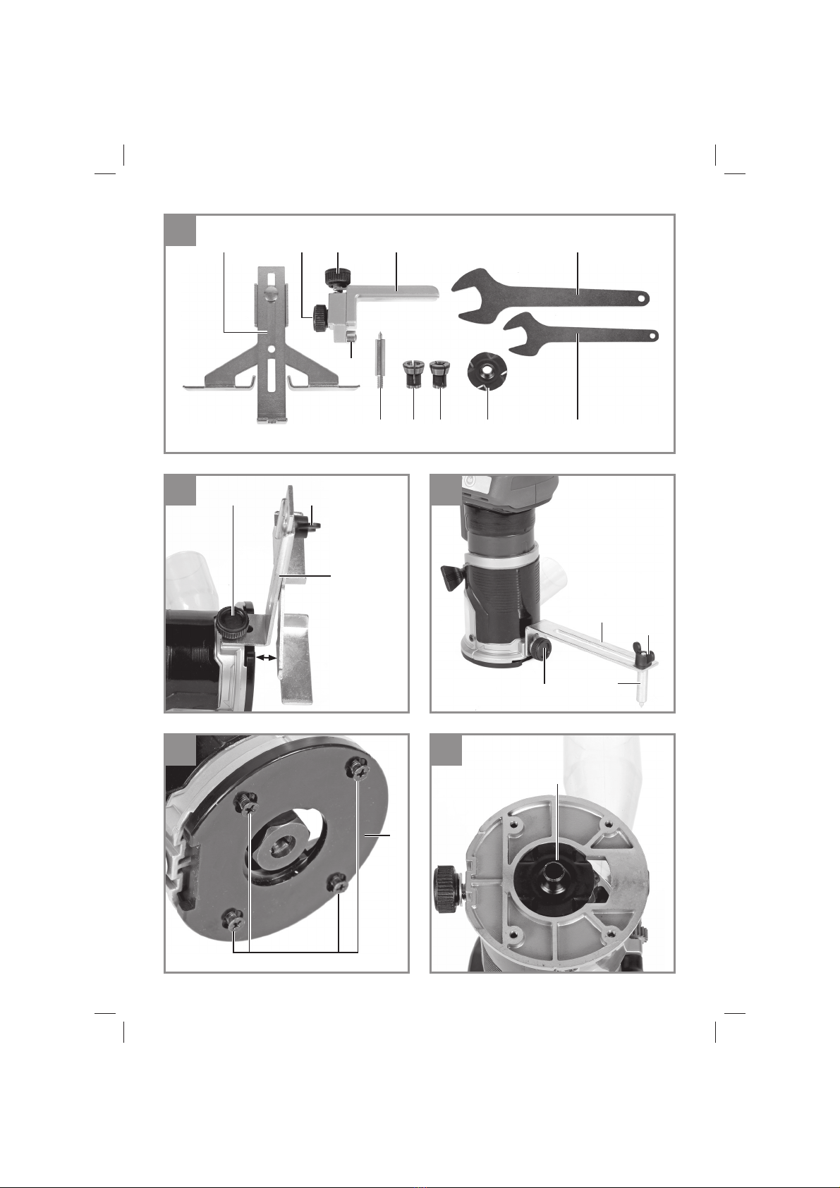
5.4 ( 5-8/ 14)
• 4 (d)
(e) ( 5)
• (14) 6
• (e) (d)
• (14) (g)
(f)
• (h)
“”
“” (i)
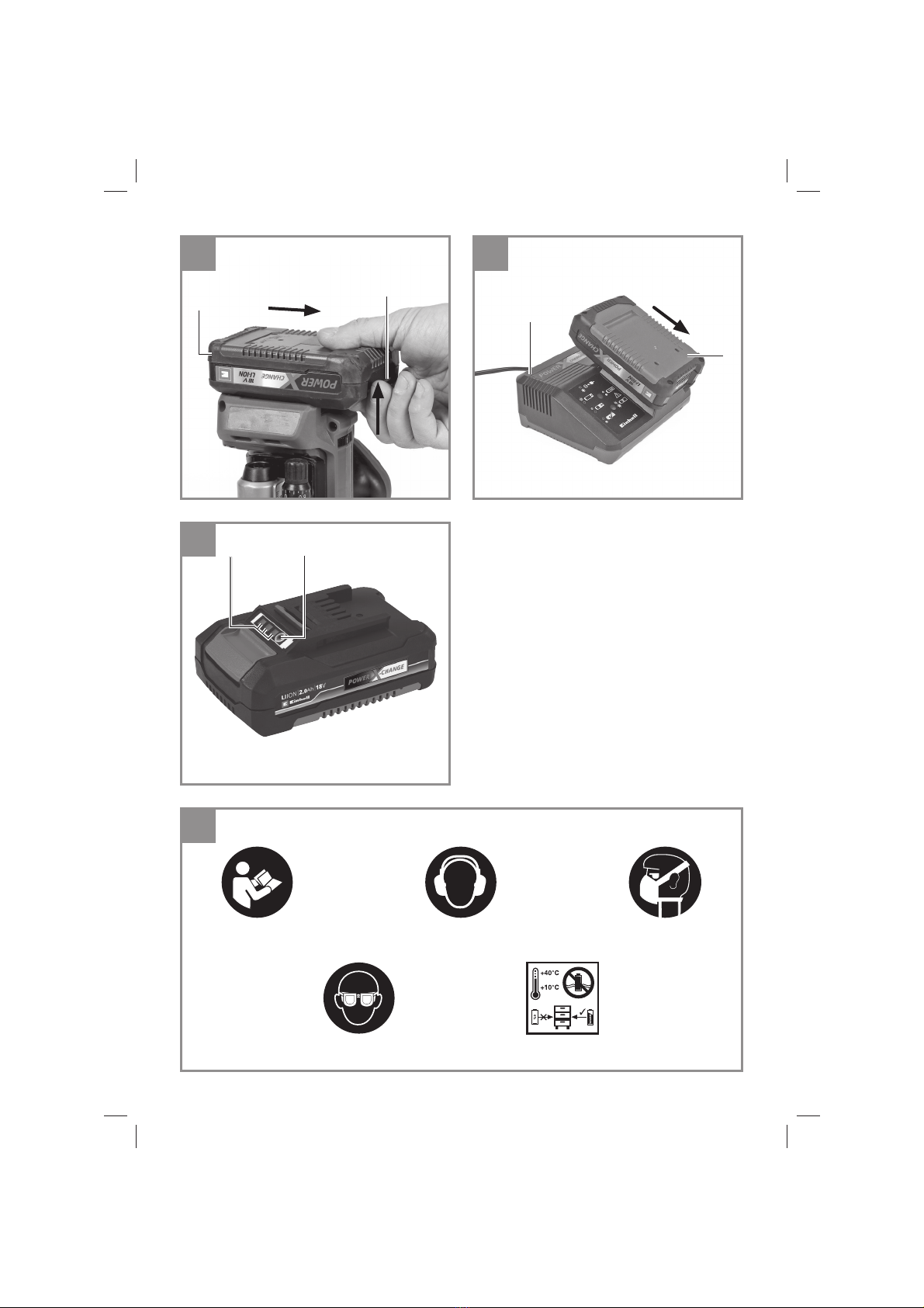
5.5 / ( 9)
!
• (1)
(20) (8)
(1)
• (9) (22)
• (8)
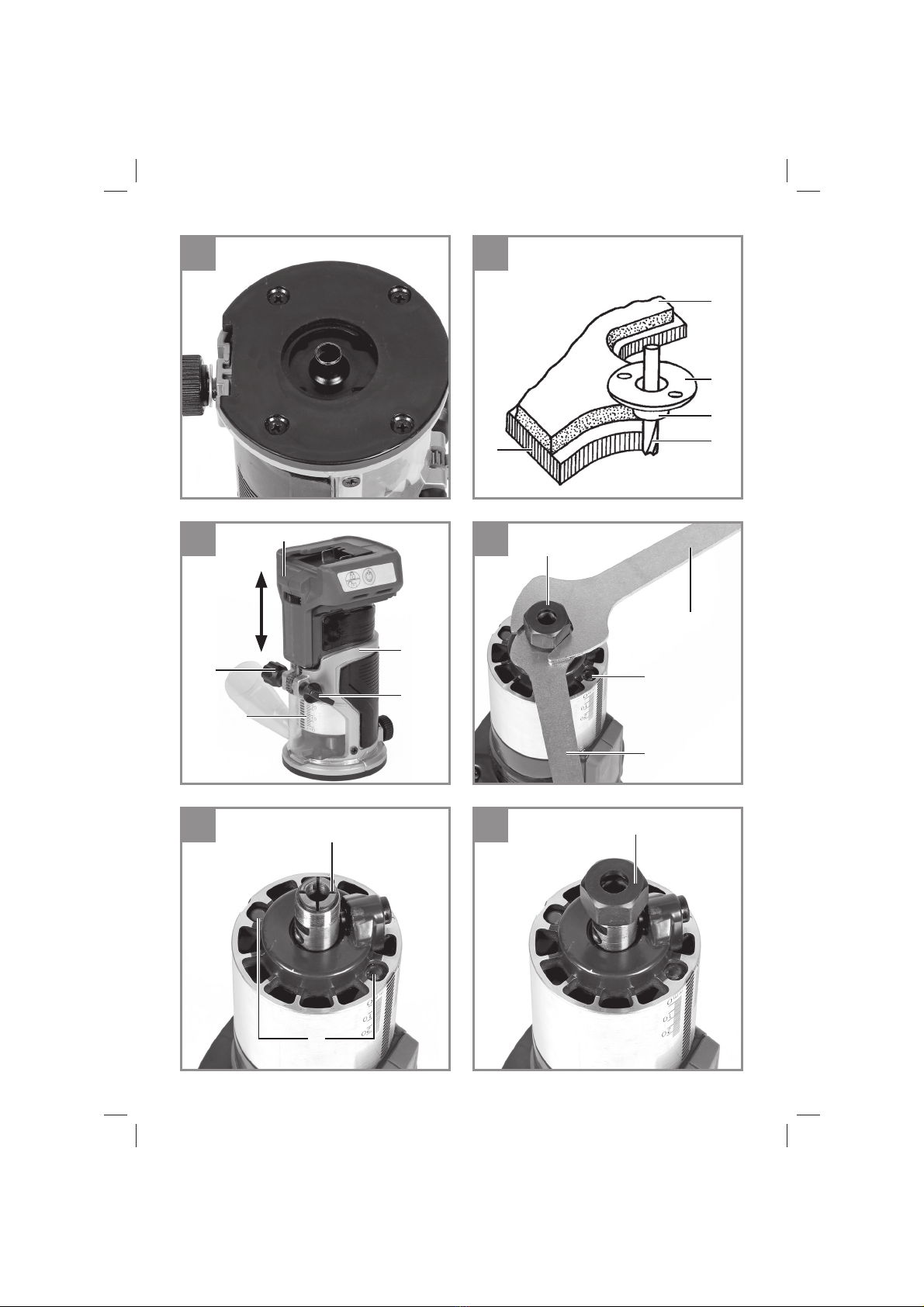
5.6 / ( 10-14)
!
!
!
!
•
(1)
5.5
• 6 . 8 .
• :
- HSS -
- TCT -
•
• :
•
• (6) (13)
• (15/16)
•
• (15/16) (i)
• (15/16) ( 11)
• (6) ( 12)
• ( 13)
• (5) (6)
( 13)
• ! (13)
!
• (6) (13)
• (15/16) 20 .
•
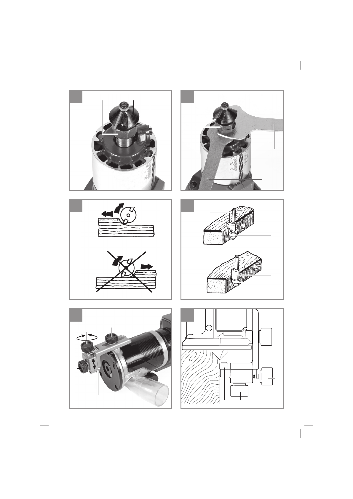
5.7 / ( 17 / 17)
• (10)
(17) 17
• (10)
• (c)
(b)
6.
•
6 . 8 .
•
•
Anl_TP_ET_18_Li_BL_SPK7_THA.indb 10Anl_TP_ET_18_Li_BL_SPK7_THA.indb 10 27.07.2023 07:48:3527.07.2023 07:48:35