eka EKF 1111 E UD User manual

USE AND INSTRUCTION MANUAL
USE AND INSTRUCTION MANUALUSE AND INSTRUCTION MANUAL
USE AND INSTRUCTION MANUAL
MOD
MODMOD
MODD
DD
D.
. .
. E
EE
EKF
KF KF
KF 1
11
11
11
11
11
11
11
1
E
EE
E
UD
UDUD
UD
–
––
–
E
EE
EKF 10
KF 10KF 10
KF 1064
6464
64
E UD
E UDE UD
E UD
–
––
–
EKF
EKF EKF
EKF 1016 E UD
1016 E UD1016 E UD
1016 E UD
rev.
rev. rev.
rev. 0
00
0
TECNOEKA
TECNOEKATECNOEKA
TECNOEKA
S.r.l.
S.r.l.S.r.l.
S.r.l.
Via
Via Via
Via Marco olo
Marco oloMarco olo
Marco olo, n.1
, n.1, n.1
, n.11
1 1
1 -
--
-
35010
3501035010
35010
Borgoricc
BorgoriccBorgoricc
Borgoricco ( adova) Italy
o ( adova) Italyo ( adova) Italy
o ( adova) Italy
Tel. +39.049.9300344
Tel. +39.049.9300344 Tel. +39.049.9300344
Tel. +39.049.9300344 –
––
–
+39.049.5791479 Fax +39.049.5794387
+39.049.5791479 Fax +39.049.5794387+39.049.5791479 Fax +39.049.5794387
+39.049.5791479 Fax +39.049.5794387
www.tecnoeka.com
www.tecnoeka.comwww.tecnoeka.com
www.tecnoeka.com
E
EE
E-
--
-mail:
mail: mail:
mail: info@tecnoeka.com
info@tecnoeka.cominfo@tecnoeka.com
info@tecnoeka.com

TECNOEKA Srl ______________________________________________________________ use and instruction manual
page 2 _________________________________________________________________________________________
CE
DECLARATION OF CONFORMITY
Annexed document II A, of
Annexed document II A, ofAnnexed document II A, of
Annexed document II A, of
directive 2006/42/EC
directive 2006/42/ECdirective 2006/42/EC
directive 2006/42/EC
Manufacturer’s name TECNOEKA Srl
TECNOEKA SrlTECNOEKA Srl
TECNOEKA Srl
Manufacturer’s address Via
Via Via
Via Marco olo
Marco oloMarco olo
Marco olo, 1
, 1, 1
, 11
11
1
-
--
-
3501
35013501
35010
00
0
Borgoricco
BorgoriccoBorgoricco
Borgoricco
( D)
( D)( D)
( D)
Manager’s name of technical file Minotto Lorenzo
Minotto LorenzoMinotto Lorenzo
Minotto Lorenzo
Manager’s address of technical file Via
Via Via
Via Marco olo
Marco oloMarco olo
Marco olo, 1
, 1, 1
, 11
11
1
-
--
-
3501
35013501
35010
00
0
Borgoricco
BorgoriccoBorgoricco
Borgoricco
( D)
( D)( D)
( D)
Type of product Electronic oven
Electronic ovenElectronic oven
Electronic oven
urpose of the product Cooking food
Cooking foodCooking food
Cooking food
Model E
EE
EKF
KF KF
KF 1111
11111111
1111
E UD
E UDE UD
E UD
–
––
–
E
EE
EKF
KF KF
KF 1064 E UD
1064 E UD1064 E UD
1064 E UD
–
––
–
EKF
EKF EKF
EKF 1016 E UD
1016 E UD1016 E UD
1016 E UD
TECNOEKA Srl declares that the mentioned above products meet the following safety
regulations:
Low voltage directive 2006/95/CE
Electromagnetic compatibility Directive 2004/108/CE.
TECNOEKA Srl declares that the mentioned above products meet the following harmonised
standards:
CEI EN 60335-1 ; CEI EN 60335-2-42
CEI EN 55014-1; CEI EN 55014-2; CEI EN 61000-3-2; CEI EN 61000-3-3; CEI EN 61000-4-2
CEI EN 61000-4-4; CEI EN 61000-4-5; CEI EN 61000-4-6; CEI EN 61000-4-11; CEI EN 62233
TECNOEKA Srl declares that the mentioned above products meet the following directives:
Machine Directive 2006/42/CE;
Directive on the general safety of products 2001/95/CE;
Directive on the restriction in the use of dangerous substances in electrical and electronic
appliances 2011/65/CE;
Directive on waste from electrical and electronic appliances 2002/96/CE (RAEE).
TECNOEKA Srl declares that the mentioned above products meet the
CE 1907/2006 (REACH) Regulation
Borgoricco, 07/01/2015. ________________________________
________________________________________________________________
________________________________
Signature of a Representative of the Board of directors
(CRISTINA LORA)
X:\Sgq\ RODOTTI\1 - FORNI\FORNO ELETTRICO\LEka\MANUALI D'USO - Forno Elettrico 40 60 90 -
LEka\Lingua Inglese\NUOVA GAMMA EF\Instruction manual EKF 1111 E UD - EKF 1064 E UD - EKF
1016 E UD - GB - rev. 1.doc

Electronic Ovens rev. 0 __________________________________ EKF 1111 E UD – EKF 1064 E UD – EKF 1016 E UD
_________________________________________________________________________________________ page 3
Ind
IndInd
Inde
ee
ex
xx
x
1
11
1
General information
General informationGeneral information
General information
1.1 Technical specifications
1.2 Technical rating plate
2
22
2
Instructions for the installer
Instructions for the installerInstructions for the installer
Instructions for the installer
2.1 Storage
2.2 Transporting the oven
2.3 Unpacking the oven
2.4 Removing the protective film
2.5 Disposing of the packaging
2.6 ositioning
2.7 Electric connection
2.8 Connection of power cable
2.9 Connection to water mains
2.10 Water outlet
2.11 Thermal breaker safety devices
2.12 Electronic circuit protection
2.13 Disposing of the oven
3
33
3
User instructions
User instructionsUser instructions
User instructions
3.1 General information
3.1.1 Residual risks
3.2 Operating instructions
3.2.1 Control panel
3.2.2 rogramming cooking time
3.2.3 rogramming cooking temperature
3.2.4 rogramming cooking climate
3.2.5 Selecting cooking stage
3.2.6 Selecting cooking temperature
3.2.7 Selecting cooking program number
3.2.8 Motors at ½ speed function
3.2.9 Stop motors function
3.2.10 re-heating function
3.2.11 Storing programs
3.2.12 Start/stop push button
3.2.13 On/off push button
3.2.14 Light push button
3.2.15 Cool cooking chamber push button
3.2.16 Self clean push button
3.2.17 Clock + 1 push button
3.2.18 Enter or change current time

TECNOEKA Srl ______________________________________________________________ use and instruction manual
page 4 _________________________________________________________________________________________
3.2.19 Start clock push button
3.2.20 rogrammed ignition
3.3 Magnetic door sensor
3.4 First ignition
3.5 Cooking techniques
3.5.1 Steam cooking
3.5.2 Convection cooking
3.5.3 Convection + steam cooking
3.6 Other cooking techniques
3.6.1 Core temperature cooking technique
3.6.2 Cooking with “∆T” (Delta-T) function
3.7 Operating methods
3.7.1 Manual cooking
3.7.2 rogrammed cooking
3.8 Black-out
3.9 Communications with C
4
44
4
Cleaning
CleaningCleaning
Cleaning
4.1 General information
4.2 Cleaning the cooking chamber
4.3 Cleaning the fans
4.4 Cleaning the door seal
4.5 Cleaning the door
4.6 Cleaning the external casing
4.7 eriods without use
5
55
5
Maintenance
MaintenanceMaintenance
Maintenance
5.1 General information
5.2 Changing the lighting lamp in the cooking chamber
5.3 Changing the door seal
5.4 ossible faults
5.5 Wiring layout
6
66
6
Technical service
Technical serviceTechnical service
Technical service
7
77
7
Informations to the consumers
Informations to the consumersInformations to the consumers
Informations to the consumers
8
88
8
The Warranty
The WarrantyThe Warranty
The Warranty

Electronic Ovens rev. 0 __________________________________ EKF 1111 E UD – EKF 1064 E UD – EKF 1016 E UD
_________________________________________________________________________________________ page 5
1
11
1.
..
.
General information
General informationGeneral information
General information
This information has been prepared for your safety and that of others and we strongly advise
reading it carefully before installing and using the oven.
This instruction handbook must be kept together with the oven for future use. If the handbook
is mislaid please ask for a copy directly from the manufacturer.
1. If, on receipt of the goods, the packaging
packagingpackaging
packaging is damaged, write the following on the
delivery note: “I REVERSE THE RIGHT TO CONTROL THE GOODS”
“I REVERSE THE RIGHT TO CONTROL THE GOODS”“I REVERSE THE RIGHT TO CONTROL THE GOODS”
“I REVERSE THE RIGHT TO CONTROL THE GOODS”, specify the damage
and get the driver to sign in acceptance; send a claim in writing to the seller within 4
calendar days from the date of receipt. No claim shall be accepted after such period.
2. The oven has been exclusively designed for cooking and heating foodstuffs, any other
use is improper.
3. This oven has been designed for professional use and must only be used by qualified
trained persons. The oven must never be left unattended when it is operating.
4. In the case of faults or poor operations, turn the oven off, close the water supply valve,
unplug from the power mains and contact the authorized Service Centre.
5. All the installation and start-up operations must only be carried out by a technically
qualified installer, conforming to the manufacturer’s instructions in the full respect of
national standards in force.
6. For the periodic maintenance and repair work, contact your nearest Service Centre and
ensure only original spare parts are used. Failure to observe this instruction automatically
involves losing all rights to the guarantee.
N.B.:
N.B.:N.B.:
N.B.:
Improper and incorrect use and fail
Improper and incorrect use and failImproper and incorrect use and fail
Improper and incorrect use and failure to observe the installation instructions releases the
ure to observe the installation instructions releases the ure to observe the installation instructions releases the
ure to observe the installation instructions releases the
manufacturer from any type of liability.
manufacturer from any type of liability. manufacturer from any type of liability.
manufacturer from any type of liability. In this sense, the instructions given in the paragraph
“ OSITIONING” must be strictly followed.
1.1
1.1 1.1
1.1 Technical specifications
Technical specificationsTechnical specifications
Technical specifications
Overall measurements:
Overall measurements:Overall measurements:
Overall measurements:
Height (with feet) cm 1
11
125
2525
25
Width cm 97
9797
97
Depth cm 85
8585
85
Weight
WeightWeight
Weight:
::
:
Kg 155
155155
155
Electric capacity:
Electric capacity:Electric capacity:
Electric capacity:
3 convection heating elements kW
15
1515
15
Max. electric capacity:
Max. electric capacity:Max. electric capacity:
Max. electric capacity:
kW
16
1616
16
Class:
Class:Class:
Class:
I
Degree of protection against humidity
Degree of protection against humidityDegree of protection against humidity
Degree of protection against humidity
I X3
Water pressure:
Water pressure:Water pressure:
Water pressure:
k a 1
11
10
00
00
0 0
0 –
––
–
2
22
20
00
00
00
0
ower supply voltage
ower supply voltageower supply voltage
ower supply voltage:
::
:
(50
(50(50
(50/60
/60/60
/60
Hz)
Hz)Hz)
Hz)
380/
380/380/
380/400V
400V400V
400V∼
∼∼
∼
3N
3N3N
3N
ower cable diameter
ower cable diameterower cable diameter
ower cable diameter:
::
:
5 x 2,5 mm
5 x 2,5 mm5 x 2,5 mm
5 x 2,5 mm
2
22
2
ower cable type
ower cable typeower cable type
ower cable type:
::
:
H07RN
H07RNH07RN
H07RN-
--
-F
FF
F
E
EE
Electric cable
lectric cablelectric cable
lectric cable
connection
connectionconnection
connection
Type Y
Type YType Y
Type Y
The noise level of the appliance w
The noise level of the appliance wThe noise level of the appliance w
The noise level of the appliance when operating is less than 70 dB
hen operating is less than 70 dBhen operating is less than 70 dB
hen operating is less than 70 dB
(A)
(A)(A)
(A).
..
.

TECNOEKA Srl ______________________________________________________________ use and instruction manual
page 6 _________________________________________________________________________________________
1.2
1.2 1.2
1.2 Technical rating plate
Technical rating plateTechnical rating plate
Technical rating plate
Tecnoeka S.r.l., Via
Marco olo
, 1
1
35010 Borgoricco ( adova) ITALY
Model
:
E
EE
E
KF
KF KF
KF
1
11
1
11
1111
11
1
11
1
E
EE
E
UD
UDUD
UD
Voltage
:
380
-
400
V
3N
50
/60
Hz
Oven capac
ity
:
kW
15
Max
.
capacity
:
kW
16
Water pressure
:
k a
1
5
0
520310727
Made in Italy
The Technical rating plate is
The Technical rating plate isThe Technical rating plate is
The Technical rating plate is
fitted on the rear panel of the oven.
fitted on the rear panel of the oven.fitted on the rear panel of the oven.
fitted on the rear panel of the oven.
2
22
2.
..
.
Instructions for the installer
Instructions for the installerInstructions for the installer
Instructions for the installer
The following instructions are addressed to the qualified installer to enable him to perform the
correct installation, electric and water connection operations in conformity with current safety
legislation in force in the place where the appliance is installed.
The manufacturer will not respond for damage to people, animals and property due to
installation errors. Likewise the manufacturer is not responsible for breakage caused to the
appliance by incorrect installation.
2.1
2.1 2.1
2.1 Storage
StorageStorage
Storage
If the appliance has been stored in a warehouse at a temperature below 0°C (min. allowed is –
10°C), it should be brought to a temperature of at least +10°C before it is turned on.
2.2
2.2 2.2
2.2 Transporting the oven
Transporting the ovenTransporting the oven
Transporting the oven
During transport, the appliance must be left in its original wooden cage to protect it against
damage.
2.3
2.3 2.3
2.3 Unpacking the oven
Unpacking the ovenUnpacking the oven
Unpacking the oven
Remove all the packaging before installation, which is formed of a wooden cage that holds the
appliance and cardboard casing to protect it. Check that the appliance has not been damaged
during transport and if any damage is discovered immediately inform your retailer and/or the
haulier.
2.4
2.4 2.4
2.4 Removing the protective film
Removing the protective filmRemoving the protective film
Removing the protective film
Before using the appliance, carefully remove the special protective film over the stainless steel
parts, without leaving any glue residue on the surfaces. If necessary, remove the residue at once
with a suitable non-inflammable solvent (e.g. acetone).
2.5
2.5 2.5
2.5 Disposing of the packaging
Disposing of the packagingDisposing of the packaging
Disposing of the packaging
The packaging must be disposed of in accordance with current legislation in force in the place
where the appliance is installed. The various types of materials (wood – paper – cardboard –
nylon – metal staples) used for the packaging must be separated and delivered to the specific
waste disposal centres. In all circumstances the environmental protection regulations must be
strictly adhered to.
SERIAL NO.
CERTIFICATION

Electronic Ovens rev. 0 __________________________________ EKF 1111 E UD – EKF 1064 E UD – EKF 1016 E UD
_________________________________________________________________________________________ page 7
2.6 osi
2.6 osi2.6 osi
2.6 ositioning
tioningtioning
tioning
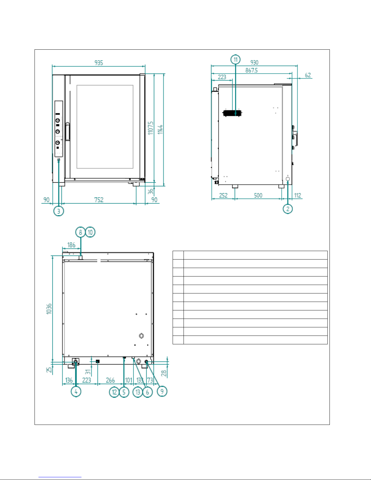
Check the place where the appliance will be installed to ensure that the passages (doors and
corridors) are wide enough (the appliance measurements are given in Fig. 1). The appliance
must be positioned in a perfectly horizontal manner on a table (preferably under a suction
hood) or other similar surface, never on the floor
never on the floor never on the floor
never on the floor (The height of the table/support must minim.
85cm from the
floor). If the oven is positioned by hand, as it weighs 155kg, it must be lifted by
at least four people. The appliance must be held on both sides at the bottom, (the points where
it can be held are clearly marked) near to the 4 feet (it is easier to lift if all 4 people synchronise
their movements).
For easier access and to allow the air to circulate freely around the appliance, leave at least 50
cm between the left side and the wall (or other appliances), and at least 10 cm between the
back and the wall and the right side and the wall (see Fig. 1). The natural ventilation that is
needed to ensure efficient working for the oven is through the openings on the walls of the
outer covering (left side and back). Consequently, it is strictly forbidden to obstruct these
aeration openings, even partially and even for short periods. Failure to observe this specific
Failure to observe this specific Failure to observe this specific
Failure to observe this specific
prohibition, shall release the manufacturer from all liability for the appliance and shall
prohibition, shall release the manufacturer from all liability for the appliance and shall prohibition, shall release the manufacturer from all liability for the appliance and shall
prohibition, shall release the manufacturer from all liability for the appliance and shall
immediately cancel any guarantee rights for the said appliance,
immediately cancel any guarantee rights for the said appliance,immediately cancel any guarantee rights for the said appliance,
immediately cancel any guarantee rights for the said appliance,
because its constructive
conformity has been voluntarily compromised.
If the appliance is installed near walls, tops, shelves or other similar items, they must not be
inflammable or sensitive to heat, otherwise they must be protected by a suitable fireproof
covering.
In all cases, all fire prevention standards must be strictly adhered to.
This appliance cannot be built in nor positioned in series with others.
2.7
2.7 2.7
2.7 Electric connection
Electric connectionElectric connection
Electric connection
The connection to the main supply must be in conformity with current legislation in force.
Before making the electrical connections, make sure that:
-the voltage and frequency values of the power supply system match the values on the
"technical data" plate affixed on the rear of appliance;
-the pressure relief valve and the system must be able to support the appliance load (see
the data on the technical rating plate;
-the power supply system must be equipped with an efficient earth connection according
the power supply system must be equipped with an efficient earth connection according the power supply system must be equipped with an efficient earth connection according
the power supply system must be equipped with an efficient earth connection according
to current regulations;
to current regulations;to current regulations;
to current regulations;
-with direct-to-mains connection, a multi-pole switch must be installed between the
appliance and the mains with a minimum opening of the overvoltage category III (4000
V) between the contacts, of a sufficient size for the load and conforming to current
regulations (e.g. an automatic magnetothermal switch);
-the multi-pole switch that is used for the connection must be easily accessible once the
appliance is installed;
-the yellow/green earth wire must not be disconnected by the switch;
the yellow/green earth wire must not be disconnected by the switch;the yellow/green earth wire must not be disconnected by the switch;
the yellow/green earth wire must not be disconnected by the switch;
-the supply voltage must not differ from the rated voltage level by ±10% when the
appliance is operating;
-make sure that after inserting the power supply cord into the terminal block it does not
come into contact with any of the cooking range's hot parts.
-if the supply cable is damaged then it must be replaced by the manufacturer or b
if the supply cable is damaged then it must be replaced by the manufacturer or bif the supply cable is damaged then it must be replaced by the manufacturer or b
if the supply cable is damaged then it must be replaced by the manufacturer or by your
y your y your
y your
technical support or by a qualified person to avoid any risk.
technical support or by a qualified person to avoid any risk.technical support or by a qualified person to avoid any risk.
technical support or by a qualified person to avoid any risk.

TECNOEKA Srl ______________________________________________________________ use and instruction manual
page 8 _________________________________________________________________________________________
Installation / connection layout
2 SERIAL SOCKET
3 SOCKET TO CONNECT THE SENSOR TO THE CORE
4 WATER OUTLET (DN 30 I E)
5 WASHING WATER INLET
6 WATER INLET (THREADED ¾” SOLENOID)
8 STEAM OUTLET
9 CABLE CLAM ( OWER LEAD)
10
WARNING! HOT SURFACE
11
DO NOT BLOCK VENTS
12
ACCESS OF WATER MAX. 200k a
13
ACCESS OF SOFTENED WATER MAX. 200k a
Fig. 1 (
Fig. 1 (Fig. 1 (
Fig. 1 (Dimensions
DimensionsDimensions
Dimensions
in mm.)
in mm.)in mm.)
in mm.)

Electronic Ovens rev. 0 __________________________________ EKF 1111 E UD – EKF 1064 E UD – EKF 1016 E UD
_________________________________________________________________________________________ page 9
2.8
2.8 2.8
2.8 Connection of power cabl
Connection of power cablConnection of power cabl
Connection of power cable
ee
e
To reach the power terminal board remove the left side of the appliance. Loosen the cable-
clamp on the back (at the bottom) of the appliance (see Fig. 1) and pass the cable through up
to near to the terminal board. Locate the leads against the terminal board so that the earth lead
is the last to detach from its terminal in the event of reverse pulling.
Connect the 3 phase
phase phase
phase leads to the terminals marked “1”
“1”“1”
“1”
“2”
“2”“2”
“2” and “
““
“3
33
3”
””
”, the neutral
neutral neutral
neutral lead to the
terminal marked “
““
“4
44
4”
””
” or “5”
“5”“5”
“5” and the earth
earth earth
earth lead to the terminal marked as shown in the
following layout:
380
380380
380-
--
-400V~3
400V~3400V~3
400V~3N
NN
N
1 2 3 4 5
(this electrical connection layout is also available near the power supply terminal board). Tighten
the cable clamp on the back (at the bottom) of the appliance and replace the left side. The
cable must correspond to those given in the “Technical specifications” table (paragraph 1.1).
The appliance must be connected to an equipotential system
equipotential system equipotential system
equipotential system after checking its efficiency
according to current regulations.
This connection must be made between different appliances using the special terminal marked
with . The equipotential lead must have a minimum diameter of 2,5mm
2
. The equipotential
terminal is on the rear of the appliance.
2.9
2.9 2.9
2.9 Connection to wa
Connection to waConnection to wa
Connection to water mains
ter mainster mains
ter mains
The oven must be supplied with softened drinking water with a hardness value of 0.5 to 5°F (It
is obligatory to use water softener to reduce the formation of scaling inside the cooking
chamber). The water pressure must be in the range of 100 to 200 k a (1.0 – 2.0 bar). If the
water pressure exceeds 2.0 bar, install a pressure reducer device upstream. If the pressure is
below 1.0 bar, use a pressure pump to increase the level.
The connection to the water supply is done using the ¾” threaded solenoid valve on the back
(at the bottom) of the appliance (see fig. 1), fitting a mechanical filter with a cut-off cock
(before connecting the filter, allow a certain amount of water to flow out in order to remove
any waste from the pipe).
2.10 Water outlet
2.10 Water outlet2.10 Water outlet
2.10 Water outlet
A drain pipe (see Fig. 1) comes out from the rear of the appliance, to drain the oven cavity. This
pipe must be connected up to a pipe made to resist steam temperatures (90°C-100°C) with an
internal diameter of 30 mm (DN 30). To prevent choking, it is best to use a rigid pipe and make
sure there are no "elbow" bends anywhere along the drain line.
Furthermore, the drain line must slope down (minimum slope 5%) along its full length (the
length in question is from the appliance's drain pipe to the drain point and must not exceed 2
metres). The drain line must run into an open floor drain (Fig.2). In addition, there must be a
free air gap of at least 25 mm (distance between the drain line coming from the appliance and
the funnel on the drain standpipe). Whatever the case, in order to comply with current hygiene
standards, the line connected to the appliance's drain pipe must not come into direct contact
with the drain point. It is advisable to include a suitable trap in the line connecting the
appliance's drain outlet to the grey water waste system, thus stopping the steam coming back
out of the drain.

TECNOEKA Srl ______________________________________________________________ use and instruction manual
page 10 _________________________________________________________________________________________
FIG. 2
FIG. 2FIG. 2
FIG. 2
FIG. 3
FIG. 3FIG. 3
FIG. 3
2.11
2.11 2.11
2.11 Thermal breaker safety devices
Thermal breaker safety devicesThermal breaker safety devices
Thermal breaker safety devices
The appliance is supplied with a manually resetting thermal breaker to protect against excessive,
dangerous temperatures which could be accidentally generated inside. If it is tripped, the device
cuts off the power supply to the appliance.
To access this device, remove the left side-panel of
the appliance.
2.12
2.12 2.12
2.12 Electronic circuit protection
Electronic circuit protectionElectronic circuit protection
Electronic circuit protection
The electronic circuit inside the electric components compartment is protected by fuses.
2.13
2.13 2.13
2.13 Disposing of the oven
Disposing of the ovenDisposing of the oven
Disposing of the oven
The appliance is made using recyclable raw materials and contains no toxic or harmful
substances for people or the environment. The appliance, and its packaging, must be disposed
of in conformity with the current regulations in force in the place of installation. The various
materials used for its construction must be separated and delivered to the specialised waste
disposal centres. In all cases the environment protection regulations must be strictly adhered to.

Electronic Ovens rev. 0 __________________________________ EKF 1111 E UD – EKF 1064 E UD – EKF 1016 E UD
_________________________________________________________________________________________ page 11
3
33
3.
..
.
User instructions
User instructionsUser instructions
User instructions
3.1 General i
3.1 General i3.1 General i
3.1 General informat
nformatnformat
nformation
ionion
ion
-When using the oven for the first time, we advise you to run it load-free at maximum
temperature for about one hour. In this way, any unpleasant smells, due to thermal
insulation, and grease residue from assembly are eliminated.
-This appliance must be exclusively used for the purposes for which it was expressly
designed, i.e. cooking foods in the oven, any other use is improper.
-The oven can be used for all oven cooking of pastry, bakery and gastronomy products,
fresh and frozen, for re-conditioning refrigerated and deep frozen foods, for steam
cooking meat, fish and vegetables.
-When placing food in the cooking chamber, allow a space of at least 40 mm between
pans to avoid over-obstructing the airflow.
-Do not use pans with edges higher than necessary: the edges act like barriers preventing
circulation of hot air.
-re-heat the oven before each time it is used to guarantee the best performance.
-For the cooking to be as even as possible, place the food evenly in each pan, considering
the size of the pieces, layers or the thickness.
-Do not salt the food when it is in the cooking chamber.
-To check the cooking cycle is proceeding correctly use the internal light in the chamber
do not open the door if it is not necessary, to avoid wasting energy and prolonging
cooking times.
3.1.1
3.1.1 3.1.1
3.1.1 Residual risks
Residual risksResidual risks
Residual risks
-After a cooking operation, open the door cautiously, to avoid a violent outflow of heat
which could cause burns.
-While the oven is in operation, pay attention to the hot zones (marked on the appliance)
of its external surfaces.
-lace the machine on a bench or similar support, at a height of at least 60 cm from the
floor.
-The bench or support must be able to support the weight of the machine and house it
correctly.
-To prevent incorrect connection of the appliance, the relevant electrical and water
connections are marked by identification plates.
-The appliance contains electrical parts and must never be washed with a jet of water or
steam.
-The appliance is electrically connected: before attempting any cleaning operation, cut
power to the appliance.

TECNOEKA Srl ______________________________________________________________ use and instruction manual
page 12 _________________________________________________________________________________________
3.2
3.2 3.2
3.2
Operating instructions
Operating instructionsOperating instructions
Operating instructions
3.2.1
3.2.1 3.2.1
3.2.1
Control panel
Control panelControl panel
Control panel
1. Time display
2. “+1” push button and hour/minute display
(on the time display)
3. Current time display push button (on the
time display)
4. Green signal light for an active stage
5. hase selection push button
6. Time setting knob (“1”)
7. Temperature display
8. Set temperature in cooking chamber
9. Actual temperature in cooking chamber
10.Set temperature for core probe
11.Actual temperature at core probe
12.Set “∆T” temperature
13.Temperature selection push button (on
temperature display)
14.Temperature setting knob (”2”)
15.Climate display led bar
(blue led = steam / red led = dry)
16.Motors at 1/2 speed push button
17.Stop motors push button
18. re-heating function push button
19.Climate setting knob (“3”)
20.Start/stop push button for cooking cycle
21.Display programs
22.Storing programs push button
23.View programs push button (1÷99)
24. On/off push button
25.Cooking chamber light push button
26.Wash boiler push button
(NOT ACTIVATED)
27.Cooking chamber cooling push button
Relay socket for the “Heart probe” (probe
“pin”) (for prepared ovens)
8
4
1
2
3
5
9
10
12
13
11
15
16
17
1
8
2
0
2
2
24
25
6
7
14
19
21
23
26
27

Electronic Ovens rev. 0 __________________________________ EKF 1111 E UD – EKF 1064 E UD – EKF 1016 E UD
_________________________________________________________________________________________ page 13
3.2.2
3.2.2 3.2.2
3.2.2 rogramming cooking time
rogramming cooking timerogramming cooking time
rogramming cooking time
To set the cooking time (from 1 minute to 4 hours) use the knob no. “1”. The set values can be
seen on the time display.
time display.time display.
time display.
3.2.3
3.2.3 3.2.3
3.2.3 rogramming cooking temperature
rogramming cooking temperaturerogramming cooking temperature
rogramming cooking temperature
To set the cooking temperature (between 50°C and 270 °C in the cooking chamber and
between 0°C and 100°C for the “∆T” and the core probe) use the knob no. “2”. The set values
can be seen on the temperature display.
temperature display.temperature display.
temperature display.
3.2.4
3.2.4 3.2.4
3.2.4 rogramming cooking climate
rogramming cooking climaterogramming cooking climate
rogramming cooking climate
To set the cooking climate (dry or steam) use knob no. “3”. The set value in percentage is
shown on the led bar
led bar led bar
led bar formed of: 10
1010
10
blue leds
blue leds blue leds
blue leds (from 10 to 100%) for the steam
steam steam
steam selection (turn
the knob in an anti-clockwise direction). The white led shows when the climate function is not
activated.
3.2.5
3.2.5 3.2.5
3.2.5 Selecting cooking stage
Selecting cooking stageSelecting cooking stage
Selecting cooking stage
To select the cooking stage (from 1 to 4) press the push button . When the green led lights
up it shows the stage has been selected. The required cooking parameters (time/temperature/
The required cooking parameters (time/temperature/ The required cooking parameters (time/temperature/
The required cooking parameters (time/temperature/
climate) can be set for each selected stage.
climate) can be set for each selected stage. climate) can be set for each selected stage.
climate) can be set for each selected stage. The push button can be pressed at any time to
check the time for each cooking stage.
When the oven is operating, the remaining cooking time can be seen for all 4 stages on the
time display (the flashing led shows which cooking phase is actually in progress).
An “infinite” time can be set in the 1
st
and 4
th
stages (turn the knob no. “1” in an anti-
clockwise direction): the time display shows the wording “inF
inF inF
inF ” (1
st
stage) or “HoLd
HoLdHoLd
HoLd” (4
th
stage –
which is useful for keeping the food hot when it is cooked). The other stages cannot be selected
in these cases.
3.2.6
3.2.6 3.2.6
3.2.6 Selecting cooking temperature
Selecting cooking temperatureSelecting cooking temperature
Selecting cooking temperature
To select the cooking temperature (in the cooking chamber / core probe ”∆T”) press the push
button . When the green led lights up it shows the selected temperature, which can be seen
on the temperature display
temperature displaytemperature display
temperature display.
Temperature in the cooking chamber
Temperature in the cooking chamberTemperature in the cooking chamber
Temperature in the cooking chamber:
When the oven is turned on the temperature in the
cooking chamber is automatically selected (led alight on ) . To set the required level turn knob
no. “2”. When the oven is operating, the set temperature (led alight on ) and the current
temperature in the cooking chamber (led alight on ) are alternatively displayed.
Core temperature in the food
Core temperature in the foodCore temperature in the food
Core temperature in the food:
::
: To set the temperature for cooking inside the food, press the
push button until the led next to the symbol lights up and then turn knob no. “2”.
When the oven is working (with the needle probe inside the food) the set temperature (led
alight on ) and the current temperature inside the food (led alight on ) are alternatively
shown.
∆
∆∆
∆T temperature (DELTA
T temperature (DELTAT temperature (DELTA
T temperature (DELTA-
--
-T)
T)T)
T): To set the temperature for the “∆T” function, press the push button
until the led lights up next to the ∆
∆∆
∆T
TT
T symbol and then turn knob no. “2”. When the oven is
working (with the needle probe inside the food) the current temperature in the cooking
chamber (led alight on ) and the set temperature for “∆T” (led alight on ∆
∆∆
∆T
TT
T) are alternatively
shown.
N.B.:
N.B.: N.B.:
N.B.: If the cooking chamber temperature and the core temperature for the food are set, the “∆T”
temperature function is automatically deactivated.
If the core temperature for the food is set and then the “∆T” temperature, the cooking chamber
temperature function is automatically deactivated.

TECNOEKA Srl ______________________________________________________________ use and instruction manual
page 14 _________________________________________________________________________________________
3.2.7
3.2.7 3.2.7
3.2.7 Selecting cooking program number
Selecting cooking program numberSelecting cooking program number
Selecting cooking program number
To select the cooking program number (there are 99 programs in all) press the push button
(from 1 to 99) or the push button (from 99 to 1). The selected program number is shown
on display programs.
display programs. display programs.
display programs. To rapidly view the programs keep the push button pressed.
3.2.8
3.2.8 3.2.8
3.2.8 Motors at
Motors at Motors at
Motors at ½
speed function
speed functionspeed function
speed function
To activate this function press the push button . When the green led lights up it confirms
the activation. This function remains operative until the push button is pressed a second time. If
this function is included in one of the four cooking stages, the passage to the next cooking
stage is automatically deactivated. This function cannot be activated during a progra
This function cannot be activated during a prograThis function cannot be activated during a progra
This function cannot be activated during a programmed
mmed mmed
mmed
cooking cycle.
cooking cycle. cooking cycle.
cooking cycle. By halving the speed of the motors (fans), the heating capacity is halved too and
therefore the cooking times and the amount to be cooked must be adjusted. (The different
noise of the motors is quite normal at reduced speed).
3.2.9
3.2.9 3.2.9
3.2.9 Sto
StoSto
Stop motors function
p motors functionp motors function
p motors function
To activate this function press the push button . When the green led lights up it confirms the
activation. This function remains operative until the push button is pressed a second time.
If this function is included in one of the cooking stages, the passage to the next cooking stage is
automatically deactivated. This function can be activated and deactivated at any time, even
This function can be activated and deactivated at any time, even This function can be activated and deactivated at any time, even
This function can be activated and deactivated at any time, even
during a programmed cooking cycle.
during a programmed cooking cycle.during a programmed cooking cycle.
during a programmed cooking cycle.
When the motors (fans) are stopped, the heating elements and climate regulation are
deactivated, therefore if this function is included in a program, it can be used to delay the start
of the cooking cycle or as a pause during the cycle (for leavening the product inside the cooking
chamber).
3.2.10
3.2.103.2.10
3.2.10
re
rere
re-
--
-heating function
heating functionheating function
heating function
To activate this function press the push button . When the green led lights up it confirms the
activation. The function is automatically deactivated when the pre
The function is automatically deactivated when the preThe function is automatically deactivated when the pre
The function is automatically deactivated when the pre-
--
-heating temperature is
heating temperature is heating temperature is
heating temperature is
reached,
reached, reached,
reached, otherwise, it can be deactivated by pressing the push button during a cooking stage
(the oven pre-heating can be cut off at any time).
If this function is activated in a programmed cooking cycle, it is not stored with the other
parameters of the program and, therefore, it must be activated each time a new cooking cycle
is started: either programmed or manual. The function adds a temperature delta
The function adds a temperature delta The function adds a temperature delta
The function adds a temperature delta ∆
∆∆
∆
only to the
only to the only to the
only to the
temperature that was set in the first stage of the cooking cycle,
temperature that was set in the first stage of the cooking cycle, temperature that was set in the first stage of the cooking cycle,
temperature that was set in the first stage of the cooking cycle, to compensate any heat loss
caused by opening the oven door to introduce the food.
If this stage is activated, when the cooking cycle starts the time display shows the wording
“HEAt”. As soon as the pre-heating temperature is reached a beeper sounds, which stops only
when the oven door is opened for introducing the food (the wording “HEAt” continues
flashing). When the door is closed, the programmed cooking cycle starts automatically and the
time display shows the set cooking time.
3.2.11
3.2.11 3.2.11
3.2.11 Storing programs
Storing programsStoring programs
Storing programs
Select the program number you wish to store. Set the parameter sequence: time/temperature
and climate for each of the four cooking stages. ress the push button until the beeper
informs you it has been stored. To cancel a stored program, just replace it with a new one with
the same number, containing the new parameters for the four cooking stages. The new
program must then be stored.

Electronic Ovens rev. 0 __________________________________ EKF 1111 E UD – EKF 1064 E UD – EKF 1016 E UD
_________________________________________________________________________________________ page 15
3.2.12
3.2.12 3.2.12
3.2.12 Start/stop push button
Start/stop push buttonStart/stop push button
Start/stop push button
Once a programmed cooking cycle has been selected or a manual cycle set, press the push
button to start cooking. The green led lights up and the beeper sounds to confirm the
cooking cycle has started. To interrupt the cycle the push button can be pressed at any time.
3.2.13
3.2.13 3.2.13
3.2.13 On/off push button
On/off push buttonOn/off push button
On/off push button
ress the push button to turn the oven on and off. When the oven is off, the green led is on
and vice versa. When the oven is cooking, this push button is disconnected: to turn the oven off
to turn the oven off to turn the oven off
to turn the oven off
you must first stop the cooking
you must first stop the cooking you must first stop the cooking
you must first stop the cooking (pressing the START/STO push button).
3.2.14
3.2.14 3.2.14
3.2.14 Light push button
Light push buttonLight push button
Light push button
ress the push button to light the cooking chamber. When the green led lights up it
confirms the light is on. The light turns off automatically after 60 seconds. If the push button is
kept pressed until the beeper sounds it confirms that the light will remain on. To turn the light
off press the push button again.
3.2.15
3.2.15 3.2.15
3.2.15
Cool cooking chamber push button
Cool cooking chamber push buttonCool cooking chamber push button
Cool cooking chamber push button
To rapidly cool the cooking chamber at the end of a cooking cycle, hold the door open and
press the push button . When the green led lights up it confirms the function is activated.
During forced ventilation, the temperature in the cooking chamber is shown moment by
moment on the temperature display.
3.2.16
3.2.16 3.2.16
3.2.16 Self clean push button
Self clean push buttonSelf clean push button
Self clean push button
The function is not activated
not activatednot activated
not activated for this model of equipment.
3.2.17
3.2.173.2.17
3.2.17
Clock + 1 push button
Clock + 1 push buttonClock + 1 push button
Clock + 1 push button
At the end of the cooking cycle the beeper sounds for 10 seconds and the figure “0000”
begins flashing on the display. While the figure is flashing, which lasts for 60 seconds, by
pressing the push button the cooking time can be extended: each time the push button is
pressed the time is increased by one minute (the option is deactivated at the end of the cooking
cycle with the probe in the core). When the oven is turned OFF the time display shows the
current time: to change or enter the time (if it is missing) press the push button.
3.2.18
3.2.183.2.18
3.2.18
Enter or change current time
Enter or change current timeEnter or change current time
Enter or change current time
With the oven turned OFF, press the push button and the two figures relative to the hour
begin flashing on the time display. Use the knob “1” to enter the current hour. The day of the
week is shown on the temperature display (1= 7 through to 7 = Sunday). Use knob no. “2” to
enter the current day. ress the push button again and the two figures will start flashing on
the time display relative to the minutes. Use knob “1” to enter the current minutes. When the
push button is pressed again the time display shows the complete time.
3.2.19
3.2.193.2.19
3.2.19
Start clo
Start cloStart clo
Start clock push button
ck push buttonck push button
ck push button
With the oven turned ON or during the cooking cycle, when the push button is pressed at
any time, the current time can be checked on the time display (the other displays are
deactivated).

TECNOEKA Srl ______________________________________________________________ use and instruction manual
page 16 _________________________________________________________________________________________
3.2.20
3.2.20 3.2.20
3.2.20 rogrammed ignition
rogrammed ignitionrogrammed ignition
rogrammed ignition
With the oven turned OFF, when the push button is pressed, the parameters are shown
that have been entered for programmed ignition: the time (time display), the day (temperature
display) and the cooking program number (program display). To change the parameters press
the push button . The two figures showing the hour begin flashing on the time display: use
the knob no. “1” to enter the required ignition hour. The figures showing the day start flashing
on the temperature display: use knob no. “2” to enter the required day (from 1 = Monday to 7
= Sunday). The two figures relative to the cooking program start flashing on the program
display: use the scroll buttons to enter the required cooking program number. ress the push
button again and the two figures showing the minutes start flashing on the time display:
use the knob no. “1” to enter the required minutes. ress the push button and the current
time is shown on the time display. ress and the green led starts flashing to confirm that
the oven is on stand-by ready for programmed ignition.
To cancel programmed ignition press the push button again.
3.3
3.3 3.3
3.3 Magnetic door sensor
Magnetic door sensorMagnetic door sensor
Magnetic door sensor
This device stops the oven and the cooking cycle each time the door is opened.
3.4
3.4 3.4
3.4
First ignition
First ignitionFirst ignition
First ignition
The oven can be used for the first time only after the chamber has been carefully cleaned with a
special detergent for stainless steel. The detergent must not contain acid substances (chloride
acid, bleach, etc.) or be abrasive. Alternatively the chamber can be washed with warm soapy
water or warm water and a drop of vinegar. Rinse well and dry with a soft cloth.
First ignition (without food inside the oven) serves to eliminate any unpleasant smells (which are
quite normal) due to the thermal insulation heating up that covers the cooking chamber and
any oil residues from assembly of the metal parts.
After turning the power on (close the unipolar switch fitted upstream from the appliance) and
the water (open the cut-off cock), proceed as follows (see the figure of the control panel):
-press the on/off push button;
-set the time (knob “1”) at one hour (shown on the time display);
-set a temperature (knob “2”) of 270°C for the cooking chamber (shown on the
temperature display);
-check the door is closed;
-press the start/stop push button: the cooking chamber starts heating up.
When the time is up, the oven turns off automatically and the beeper sounds for 10 seconds.
3.5
3.5 3.5
3.5 Cooking techniques
Cooking techniquesCooking techniques
Cooking techniques
There are three different cooking techniques with this oven which can be used singularly, one
after the other or combined.
3.5.1
3.5.1 3.5.1
3.5.1
Steam cooking (moist heat)
Steam cooking (moist heat)Steam cooking (moist heat)
Steam cooking (moist heat)
The climate regulation system which allows dividing the humidity production that should be set
at 100% (humidity \ continuous steam) , while the cooking chamber temperature can be set
between 105°C and 115°C.
Steam cooking is indicated where a boiled effect is required, and it has the advantage of
leaving the nutritional content of the food unchanged (the vitamins and flavour of the food are
conserved), the outer appearance (the colour is conserved, no lumps or air bubbles are formed
and the surface does not break up) and the weight is conserved, as no liquids are lost from the
food during cooking.

Electronic Ovens rev. 0 __________________________________ EKF 1111 E UD – EKF 1064 E UD – EKF 1016 E UD
_________________________________________________________________________________________ page 17
3.5.2
3.5.2 3.5.2
3.5.2 Convection cooking (dry heat)
Convection cooking (dry heat)Convection cooking (dry heat)
Convection cooking (dry heat)
The heating elements heat the dry air inside the cooking chamber. This heated air is evenly
distributed by the high speed of the fans. This gives an even temperature throughout the
cooking chamber and even cooking even when the oven is full.
This means that different types of food can be cooked on the various shelves (as long as they
need the same cooking temperature) without flavours and smells being mixed together.
The cooking chamber temperature can be set between 50°C and 270°C.
Besides evenly browning the food without having to turn it, convection cooking can be used to
cook au gratin and is particularly convenient for rapid defreezing, for sterilising preserves and
drying mushrooms and fruit.
3.5.3
3.5.3 3.5.3
3.5.3 Convection + humidity cooking (dry heat + moi
Convection + humidity cooking (dry heat + moiConvection + humidity cooking (dry heat + moi
Convection + humidity cooking (dry heat + moist heat)
st heat)st heat)
st heat)
This type of cooking exploits the combination of dry and moist heat. They are dosed by the
climate regulation system which can divide, in percentage, the production of steam and the
production of dry heat (drying the cooking chamber), optimising the cooking climate for each
dish.
The cooking chamber temperature can be set between 50°C and 270°C.
The fact of using a hot-moist climate inside the cooking chamber with variable temperature and
moisture levels, is the most convenient and efficient way of cooking: cooking times are reduced,
the surface of the foods remains soft and does not form a crust, there is little weight loss and
the fatty mass is reduced.
The special hot-moist climate at low temperatures is ideal for re-conditioning food.
3.6
3.6 3.6
3.6 Other cooking techniques
Other cooking techniquesOther cooking techniques
Other cooking techniques
3.6.1
3.6.1 3.6.1
3.6.1 Core temperature cooking technique
Core temperature cooking techniqueCore temperature cooking technique
Core temperature cooking technique
The temperature can be set inside the core of the food to be cooked, using the special needle
core probe. The probe must be pushed into the centre of the food in the thickest part, avoiding
the bones. lace the food inside the cooking chamber and pull out the thermal probe lead and
close the oven door. The probe plug must be plugged into the special socket (see Fig. 1) at the
bottom of the control panel. ress the push button to select the core cooking temperature
(led alight on ) between 0°C and 100°C using knob no. “2”, the temperature is shown on
the temperature display.
When a cooking cycle is started with a core probe stage included (the time display shows the
wording “ rob”), when the set temperature is reached inside the food the cooking cycle passes
onto the next stage no matter what time has been set. If the core probe is activated within any
of the four stages, with the other three deactivated, the cooking cycle finishes automatically
when the set temperature inside the food is reached, no matter what time has been set.
Cooking with the core probe can be graduated over the four stages (for very delicate cooking)
and, for each stage, the temperature and the climate inside the cooking chamber can be set
besides the temperature inside the food.
As the thermal probe is a needle which can easily be removed or broken, we advise setting the
cooking time for the stage that it is used in.
If the probe is connected and operating, the stage finishes when the set temperature is reached;
otherwise, if the probe is not connected or is broken, the stage finishes at the set time.
If the probe is not connected or is broken, when the cooking cycle starts the beeper sounds
intermittently for 10 seconds, the time display shows the flashing message “ rob” and the
previously set temperature disappears from the temperature display (
-
--
-
-
--
-
-
--
-
).
The core temperature of the food can also be measured (when no temperature has been set): it
is sufficient to slide the needle probe into the food.

TECNOEKA Srl ______________________________________________________________ use and instruction manual
page 18 _________________________________________________________________________________________
In this case, when the cooking cycle has been started, when the push button is pressed the
temperature is selected automatically (shown on the temperature display) that is measured by
the probe (led alight next to ).
Warning
WarningWarning
Warning:
Before removing the food from the oven after cooking with the core needle probe.
Carefully remove the hot probe from the cooked food, taking care not to leave it
hanging out of the cooking chamber as it could cause burns.
We advise leaving it to cool down before using it again – to avoid damaging pricks in the
food.
To prevent any irreparable damage to the thermal piercing probe (core probe) do not
use it in high temperature cooking ABOVE 230°C, and ensure that the probe lead is not
touching any hot metal surfaces inside the oven.
3.6.2
3.6.2 3.6.2
3.6.2 Cooking with
Cooking withCooking with
Cooking with
“
““
“∆
∆∆
∆T” (DELTA
T” (DELTAT” (DELTA
T” (DELTA-
--
-T) function
T) functionT) function
T) function
This function allows keeping the difference (∆T) between the temperature inside the food
(measured by the needle probe) and the temperature in the cooking chamber constant. This
means that the temperature in the cooking chamber is the sum of the temperature inside the
food and a fixed “∆T” temperature that is set by the user (see the graph).
The Delta
-
T temperature is the difference between the
temperature inside the food and the temperature in the
cooking chamber
In practical terms, there is a gradual increase of the temperature in the cooking chamber, with a
constant difference with respect to the temperature inside the food which, thanks to this
constant difference, is cooked slowly and gently (in meat the proteins are protected, as no
surface tension is caused by the rapid formation of the crust).
After selecting the temperature inside the food (core temperature) and setting the level (knob
“2”) press the push button again to select the “∆T” function (the led next to the ∆
∆∆
∆T
T T
T symbol
lights up) and to set the temperature (knob “2”) (on the basis of our experience this
temperature should be between 30°C and 70°C).
When the “∆T” function is used for cooking, the method for using the needle probe is the
same as that described in paragraph 3.6.1.
0
50
100
150
200
Cooking temperature (°C)
Cooking time (min.)
Delta T temperature
∆
∆∆
∆
Cooking chamber
temperature
Temperature
inside the food

Electronic Ovens rev. 0 __________________________________ EKF 1111 E UD – EKF 1064 E UD – EKF 1016 E UD
_________________________________________________________________________________________ page 19
3.7
3.7 3.7
3.7 Operating methods
Operating methodsOperating methods
Operating methods
3.7.1
3.7.1 3.7.1
3.7.1 Manual
ManualManual
Manual
cooking
cookingcooking
cooking
After turning the oven ON (green led off), set the various cooking parameters.
Set the cooking time (shown on the time display) using the knob no. “1”:
-“inF” (stages excluded /stage led off)
-from 1 minute to 4 hours per stage (“inF” excluded / stage leds alight)
Set the cooking temperature (shown on the temperature display) for one or more stages, using
knob no. “2”:
-cooking chamber (from 50°C to 270°C / led alight on )
-core probe (from 0°C to 100°C / led alight on )
-∆T / DELTA-T (from 0°C to 100°C/ led alight on ∆
∆∆
∆T
TT
T)
Set the cooking climate (shown on the led bar) for one or more stages, using knob no. “3”:
-neutral (white led alight)
-only steam (all 10 blue leds alight /100%)
-variable steam (blue leds 1 to 9 alight /from 10 to 90)
Set the pre-heating function (optional) pressing the push button .
Set the motors at ½ speed function (optional) for one or more stages, pressing the push button
.
ress the push button to start the cooking cycle.
Remember
RememberRemember
Remember:
1.
If the cooking cycle is not controlled by the core probe and has been divided in one or
more timed stages, the oven turns off automatically when the set time for the single
stage or all the different stages together is over. If an “inF” (infinite) time has been set,
the oven continues until the operator turns it off manually pressing the push button .
2.
If the cooking cycle is controlled by the core probe and has been divided in one or more
stages, timed if required, when the temperature set on the probe is reached it passes
onto the next stage; if it has been set for a single stage, timed if required, or for an “inF”
time, the cycle finishes and the oven turns off automatically, no matter what time was
set for the stage.
3.7.2
3.7.2 3.7.2
3.7.2 rogrammed cooking
rogrammed cookingrogrammed cooking
rogrammed cooking
When the cooking programs have already been stored (a cooking cycle corresponds to each
program number for a specific type of food) it is very easy to use them.
Turn the oven ON (green light off) select the stored program number (shown on the program
display) using the push buttons or .
ress the push button to start the cooking cycle.
At the end of the cooking cycle the oven turns of automatically and the beeper sounds for 10
seconds.
Remember
RememberRemember
Remember: Before beginning the cooking cycle, the parameters can be checked that have
been set for the four stages (pres the push button ) and they can be changed
if wished. For the changed parameters to become operative, they must be stored
(press the push button until the confirming beep is heard).

TECNOEKA Srl ______________________________________________________________ use and instruction manual
page 20 _________________________________________________________________________________________
3.8 Black
3.8 Black3.8 Black
3.8 Black-
--
-out
outout
out
When the power supply returns after a black-out, the oven will continue working counting the
remaining time for the cooking cycle after the interruption.
3.9
3.9 3.9
3.9 Communications with C
Communications with CCommunications with C
Communications with C
At the bottom of the control panel (seen from below) there is an inlet (remove the rubber
protection) for a serial gate for interactive communications with a C.
If this gate is connected to a C with wineka software
wineka software wineka software
wineka software (optional), up to 99 preset cooking
programs can be transmitted to the oven memory for all the operating parameters; likewise, the
cooking programs that are already stored in the oven memory can be acquired by the C.
Certain operational parameters for the oven can also be changed.
4
44
4.
..
.
Cleaning
CleaningCleaning
Cleaning
4.1
4.1 4.1
4.1 General information
General informationGeneral information
General information
Before beginning any sort of cleaning work on the appliance, turn the power supply off (at the
magnetothermal safety switch) and the water supply (by closing the cut-off cock) and then let
the oven cool down completely.
The appliance must be cleaned frequently, preferably daily, to guarantee best operations and
long life. This is an electric appliance therefore for obvious reasons water should not be used in
excess for cleaning. However, it is absolutely forbidden to wash the appliance with water jets,
it is absolutely forbidden to wash the appliance with water jets, it is absolutely forbidden to wash the appliance with water jets,
it is absolutely forbidden to wash the appliance with water jets,
especially if they are pointed towards the aeration vents on the metal surface of the outside
especially if they are pointed towards the aeration vents on the metal surface of the outside especially if they are pointed towards the aeration vents on the metal surface of the outside
especially if they are pointed towards the aeration vents on the metal surface of the outside
casing
casing casing
casing (this could cause dangerous infiltrations that would damage the electric parts).
If grease remover detergents are used to clean the stainless steel, ensure they do not contain
corrosive acids (no sort of chlorine, even if it is diluted) or abrasive products. Follow the
indications given on the product and the warnings about its use, wearing rubber gloves during
cleaning.
Do not use iron pads, steel wool or scrapers as they would ruin the surfaces.
Do not leave food on the steel surfaces for a long time that contain acid substances (lemon
juice, vinegar, salt, etc.) as they could cause corrosion.
4.
4.4.
4.2
22
2
Cleaning the cooking chamber
Cleaning the cooking chamberCleaning the cooking chamber
Cleaning the cooking chamber
For hygienic reasons, it is good practice to clean the cooking chamber at the end of each
cooking cycle, otherwise it should be cleaned at least once at the end of each day’s use.
For easier cleaning, remove the side grills by unscrewing the 4 fixing screws (hold the reeded
nut between your thumb and forefinger and turn it in an anti-clockwise direction) remove the
drainage plug on the bottom and proceed as follows:
-spray a special degreasing product for stainless steel on the external walls, on the fan
casing (do not spray it through the fan grids) and on the glass inside the door;
-leave the product to work for approximately 20 minutes with the door closed;
-turn the oven on to 70-80°C;
-run a cycle with maximum steam (100%) for around 15 minutes;
-when the cycle is complete turn the oven off, leave the cooking chamber to cool down
and rinse well;
-Dry with a soft cloth or run a heating cycle, with the temperature at 150-160°C for
about 10 minutes (the cycle can be repeated if necessary).
The side grills and drainage plug must be cleaned separately and then replaced.
When cleaning is terminated, leave the oven door slightly ajar.
4.
4.4.
4.3
33
3
Cleaning the fa
Cleaning the faCleaning the fa
Cleaning the fans
nsns
ns
The fans must be periodically cleaned with specific anti-limescale products. All the parts must be
carefully cleaned, removing all limescale deposits.
To have access to the fans remove the fan casing after removing the screws that fix it to the
cooking chamber. When cleaning is complete, replace the casing and screws.
This manual suits for next models
2
Table of contents
Other eka Oven manuals

eka
eka MKF 464 S User manual

eka
eka EKF 523E UD User manual

eka
eka MILLENNIAL MKF 464 TS User manual

eka
eka EKF 523 NT User manual

eka
eka MKF 464 BM Manual

eka
eka KF 725 UD User manual

eka
eka EKF 711UD-EKF 664UD-EKF 664 UD-HTEKF 664... User manual

eka
eka EKF 416 AL P User manual

eka
eka ekf 711 p User manual

eka
eka KF 630 D UD User manual
Popular Oven manuals by other brands

DOREGRILL
DOREGRILL Ginox 4 E instruction manual

Lincoln
Lincoln Impinger Low Profile Advantage Digital... Parts and service manual

ARC
ARC AOS6SE1 Other

Robam
Robam KWS260-R308 Operation manual

Fisher & Paykel
Fisher & Paykel Astro B1452R user guide

DeLonghi
DeLonghi DE 906 GWF Installation and service & use and care instructions