_ TECNOEKA Srl __________________________________________________________ use and instructi n manual _
_ page. 6 ________________________________________________________________________________________
1.
1. 1.
1. Technical service
Technical serviceTechnical service
Technical service
A technical check-up nce r twice a year helps pr l ng the life f the appliance and
guarantees better perati n. Make sure that assistance is carried ut s lely and exclusively by
qualified pers nnel. F r any spare parts rders r f r any inf rmati n ab ut the appliance,
always menti n the serial number and m del (data indicated n the "technical data" plate at
the rear f the ven).
2.
2. 2.
2. General warnings
General warningsGeneral warnings
General warnings
Very imp rtant!: keep this instructi n b k t gether with the appliance f r future
c nsultati n.
These warnings were drafted f r y ur safety and f r that f thers. Please read them
carefully bef re installing r using the appliance:
-If, n receipt f the g ds, the packaging
packagingpackaging
packaging is damaged, write the f ll wing n the delivery
n te: “I REVERSE THE RIGHT TO CONTROL THE GOODS
I REVERSE THE RIGHT TO CONTROL THE GOODSI REVERSE THE RIGHT TO CONTROL THE GOODS
I REVERSE THE RIGHT TO CONTROL THE GOODS”, specify the damage and get
the driver t sign in acceptance; send a claim in writing t the seller within 4 calendar
days fr m the date f receipt. N claim shall be accepted after such peri d.
-The wareh use inside temperature must n t be l wer than -9°C; therwise, the
therm stat (regulati n and safety therm stat) c ntr l devices f the machine will be
damaged. Failure t bserve this pr hibiti n invalidates any resp nsibility f the
manufacturer f the machine.
-The appliance is intended f r pr fessi nal use and must be utilised by qualified pers nnel
trained t use it.
-Any m dificati n which may be necessary n the electrical system t enable installati n
f the appliance, must be carried ut s lely by c mpetent pers nnel.
-It is danger us t m dify r attempt t m dify the characteristics f this appliance.
-Never clean the appliance with direct water jets, because, if any water enters, it c uld
limit the machine's safety .
-Bef re d ing any maintenance r cleaning j bs, disc nnect the appliance fr m the
electrical mains and all w it t c l.
-When the tilting d r is wide pen, d n t put anything n the surface, because the
d r hinges c uld be irreparably damaged.
-D n t attempt t carry ut the peri dic c ntr ls r any repairs by y urself. C ntact the
nearest Service Centre and use nly riginal spare parts.
N.B.:
N.B.: N.B.:
N.B.: Impr per r inc rrect use and failure t bserve the installati n instructi ns shall release
Impr per r inc rrect use and failure t bserve the installati n instructi ns shall release Impr per r inc rrect use and failure t bserve the installati n instructi ns shall release
Impr per r inc rrect use and failure t bserve the installati n instructi ns shall release
the manufacture fr m all resp nsibility.
the manufacture fr m all resp nsibility.the manufacture fr m all resp nsibility.
the manufacture fr m all resp nsibility.
In thi
In thiIn thi
In this c nnecti n, the directives in the
s c nnecti n, the directives in the s c nnecti n, the directives in the
s c nnecti n, the directives in the
"POSITIONING" paragraph must be strictly bserved.
"POSITIONING" paragraph must be strictly bserved."POSITIONING" paragraph must be strictly bserved.
"POSITIONING" paragraph must be strictly bserved.
3.
3. 3.
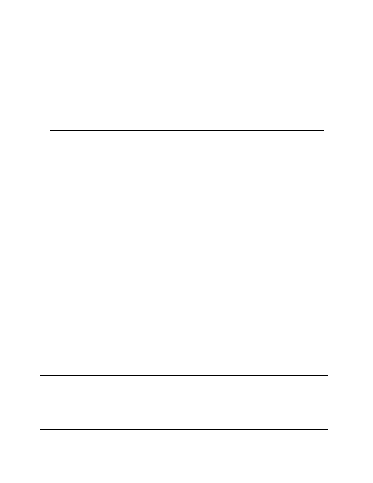
3. Technical specificati ns
Technical specificati nsTechnical specificati ns
Technical specificati ns
KF 630 D UD
KF 630 D UDKF 630 D UD
KF 630 D UD
KF 733 D UD
KF 733 D UDKF 733 D UD
KF 733 D UD
KF 937 D UD
KF 937 D UDKF 937 D UD
KF 937 D UD
KF 966 D AL
KF 966 D AL KF 966 D AL
KF 966 D AL UD
UDUD
UD
KF 966 D UD
KF 966 D UDKF 966 D UD
KF 966 D UD
Dimensi ns f appliance
Dimensi ns f applianceDimensi ns f appliance
Dimensi ns f appliance LxDxH(mm)
590x590x595
590x590x595590x590x595
590x590x595
670x625x555
670x625x555670x625x555
670x625x555
790x665x505
790x665x505790x665x505
790x665x505
790x6
790x6790x6
790x665x635
65x63565x635
65x635
Weight
Weight Weight
Weight (Kg)
3
33
39
99
9
40
4040
40
45
4545
45
5
55
55
55
5
C king chamber V l.
C king chamber V l. C king chamber V l.
C king chamber V l. (dm
3
=lt)
55
5555
55
60
6060
60
60
6060
60
91
9191
91
C nvecti n heating element
C nvecti n heating element C nvecti n heating element
C nvecti n heating element (kW)
2,7
2,72,7
2,7
3,0
3,03,0
3,0
3,5
3,53,5
3,5
3,0
3,03,0
3,0
Max. abs rbed p wer
Max. abs rbed p werMax. abs rbed p wer
Max. abs rbed p wer
(kW)
2,9
2,92,9
2,9
3,2
3,23,2
3,2
3,
3,3,
3,7
77
7
6,4
6,46,4
6,4
P wer supply v ltage
P wer supply v ltage P wer supply v ltage
P wer supply v ltage
(V) (50
(50(50
(50/60
/60/60
/60Hz)
Hz) Hz)
Hz) AC 220/230 V
AC 220/230 V AC 220/230 V
AC 220/230 V
380/400 2N
380/400 2N380/400 2N
380/400 2N
(50
(50(50
(50/60
/60/60
/60Hz)
Hz)Hz)
Hz)
P wer
P werP wer
P wer cable diameter
cable diameter cable diameter
cable diameter
3x1,5 mm
3x1,5 mm3x1,5 mm
3x1,5 mm
2
22
2
4x2,5
4x2,5 4x2,5
4x2,5 mm
mmmm
mm
2
22
2
Type f cable
Type f cableType f cable
Type f cable
H07RN
H07RNH07RN
H07RN-
--
-F
FF
F
Class
ClassClass
Class
I (against electric sh cks)
I (against electric sh cks)I (against electric sh cks)
I (against electric sh cks)
The n ise level f the appliance in perati n is bel w 70 dB (A).
The n ise level f the appliance in perati n is bel w 70 dB (A).The n ise level f the appliance in perati n is bel w 70 dB (A).
The n ise level f the appliance in perati n is bel w 70 dB (A).
The "technical data" plate is p siti ned n the rear panel f the appliance.
The "technical data" plate is p siti ned n the rear panel f the appliance.The "technical data" plate is p siti ned n the rear panel f the appliance.
The "technical data" plate is p siti ned n the rear panel f the appliance.