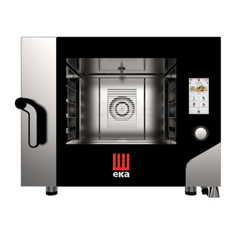
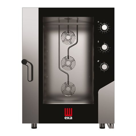
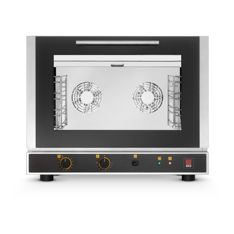
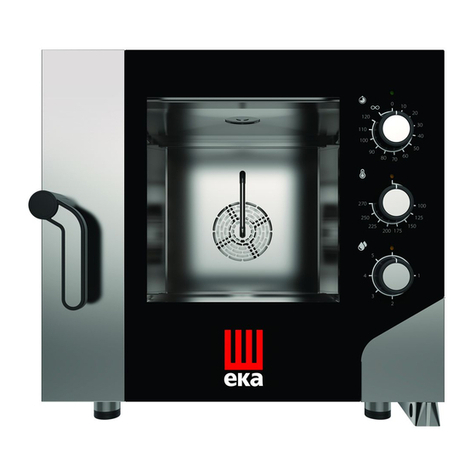
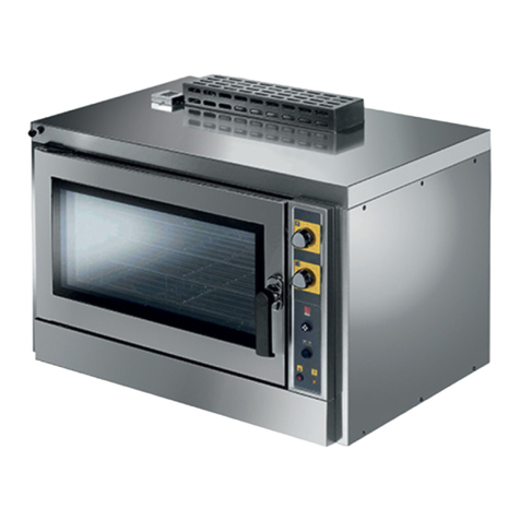
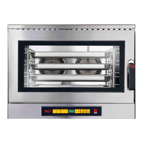
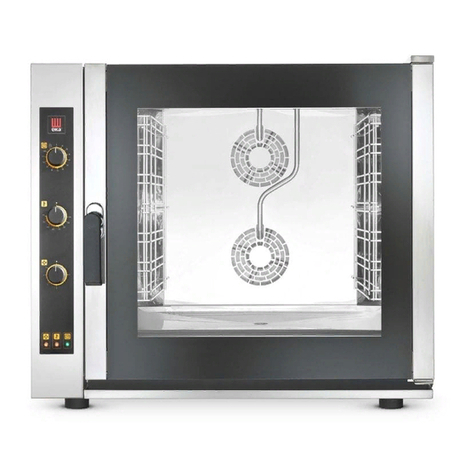
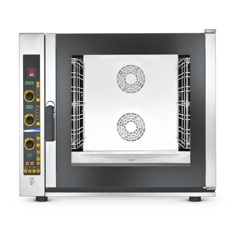
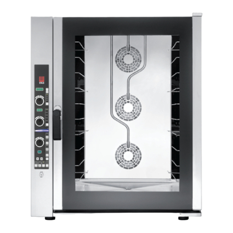
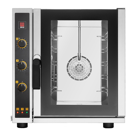
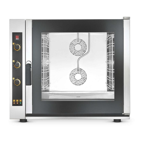
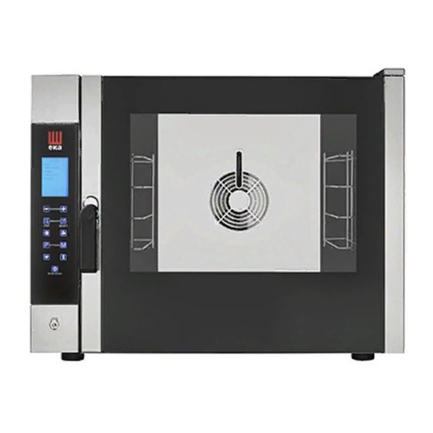
eka MKF 464 BM Manual

fffffssdsdsdsdsdsELECTRONIC BLACK MASK OVENS
TRANSLATION OF ORIGINAL INSTALLATION AND
MAINTENANCE MANUAL
ELECTRONIC BLACK MASK OVENS
MKF 464 BM- MKF 416 BM - MKF 511 BM - MKF 611 CBM
MKF 623 CBM - MKF 664 BM –MKF 616 BM –MKF 621 BM –MKF 711 BM
MKF 1011 CBM - MKF 1064 BM –MKF 1016 BM –MKF 1111 BM
MKF 1021 BM –MKF 1664 BM –MKF 2011 BM

1

2
CONTENTS
1. SERVIZIO TECNICO (TECHNICAL SERVICE) ____________________________________________________ 3
2. GENERAL INFORMATION __________________________________________________________________ 3
3. INSTRUCTIONS FOR THE INSTALLER _________________________________________________________ 4
3.1 Storage __________________________________________________________________________ 4
3.2 Transportation of the appliance ______________________________________________________ 4
3.3 Unpacking the appliance ____________________________________________________________ 4
3.4 Removal of the protective film _______________________________________________________ 4
3.5 Protective film/package disposal ______________________________________________________ 4
3.6.1 Table top oven placement _________________________________________________________ 5
3.6.2 Stacking ovens on other appliances _________________________________________________ 5
3.6.3 Placement of floor-standing ovens with trolley ________________________________________ 5
3.7 Electrical connection________________________________________________________________ 6
3.8 Power supply cable connection (replacement) __________________________________________ 6
3.9 Type of connection to the mains _____________________________________________________ 7
3.10 Connection to the water mains _____________________________________________________ 9
3.11 Water drain_____________________________________________________________________ 10
3.11.1 Water drain for floor ovens ______________________________________________________ 11
3.11.2 Water drain for tabletop ovens ___________________________________________________ 11
3.12 Steam drain_____________________________________________________________________ 11
4. MAINTENANCE INSTRUCTIONS____________________________________________________________ 12
4.1 Access to the components for inspection _____________________________________________ 12
4.2 Safety thermal device______________________________________________________________ 12
4.3 Electronic circuit protection _________________________________________________________ 13
4.4 Replacing the cooking chamber gasket _______________________________________________ 13
4.5 Handle closure adjustment _________________________________________________________ 13
4.6 Checking the cooking chamber gasket “seal” _________________________________________ 13
4.7 Residual risks_____________________________________________________________________ 14
5. TROUBLESHOOTING _____________________________________________________________________ 15
6. POSSIBLE ALARMS ______________________________________________________________________ 16
7. TECHNICAL SUPPORT ___________________________________________________________________ 17
8. DISPOSAL OF THE APPLIANCE_____________________________________________________________ 17
9. CONVENTIONAL WARRANTY _____________________________________________________________ 17
10. AVAILABILITY AND SUPPLY OF SPARE PARTS ____________________________________________ 18
11. APPLICABLE LAW AND COMPETENT COURT_____________________________________________ 18

3
1. SERVIZIO TECNICO (TECHNICAL SERVICE)
For periodic maintenance checks and repairs, contact your nearest Support Centre and only use original
spare parts. Failure to comply with this provision shall forfeit the warranty right.
2. GENERAL INFORMATION
It is essential for this instruction manual to be stored together with the appliance for future referencing; in
the event of misplacing it, a copy must be obtained directly from the manufacturer.
This information has been prepared for your safety and that of others; therefore we kindly ask you to read
it carefully before installing and using the appliance.
Upon reception of the goods, if the packaging is not intact or is damaged, report the following: “GOODS
SUBJECT TO INSPECTION”, with the specification of the damage and countersigned by the driver; file a
written complaint with the vendor within 4 calendar days (not business days) from the date of delivery,
after which no complaints shall be accepted.
The appliance is intended for professional use in industrial and professional kitchens and must only be used
by skilled personnel who have been trained on its proper use. For safety reasons the appliance must be
supervised during operation.
The appliance is not intended to be used by children and/or persons with impaired physical, sensory or
mental abilities, or who lack experience or knowledge, unless they are supervised by a person responsible
for their safety, or who has been instructed on using the appliance.
It is hazardous to modify or attempt to modify the features of this appliance.
The appliance must never be cleaned with direct water or steam jets, since any ingress of water might
affect its safety.
Before maintenance or cleaning disconnect the appliance from the power supply mains and let it cool.
In the event of failure or poor operation, switch off the appliance, close the water supply cock, disconnect
the power supply and contact an authorised Support Centre.
Any modification to the electrical system that might be required to install the appliance must be carried out
by competent personnel only.
All installation and commissioning operations must exclusively be performed by technically skilled installers,
according to the manufacturer's instructions and in compliance with national standards in force.
Note: The inappropriate or incorrect use and failure to comply with installation rules shall invalidate any
Manufacturer liability. To this regard, the instructions laid out in the “POSITIONING”paragraph must be
strictly complied with.

4
3. INSTRUCTIONS FOR THE INSTALLER
The following instructions are intended for skilled installers, to perform installation, electrical and water
connection operations in the most correct manner and according to the safety regulations in force in the
country of installation of the appliance.
The Manufacturing Company shall not be liable for damage or harm to persons, pets or property arising
from installation errors. Nor are they responsible for any appliance breakage caused by faulty installation.
3.1 Storage
If the appliance is stored in a warehouse, the ambient temperature must never drop below 0°C. Before
switching on the appliance it must be brought to a temperature of at least +10°C.
3.2 Transportation of the appliance
During transportation the appliance must be left in its packaging in order to protect it from any external
damage.
The weight of the appliance must also be taken into account in order to prevent overturning.
3.3 Unpacking the appliance
Remove the packaging before installation. It consists of a wooden pallet supporting the appliance and a
cardboard casing protecting it. Ensure the appliance has not undergone any damage during transport;
otherwise immediately alert your dealer and/or carrier.
3.4 Removal of the protective film
Before using the appliance accurately remove the special film protecting the stainless steel components,
avoiding glue residues on the surfaces; if required, immediately remove them using an appropriate non
flammable solvent. Do not use any tools that might scratch the surfaces or any acid-based or abrasive
detergents.
3.5 Protective film/package disposal
TECNOEKA has been committed for years to increasing the environmental compatibility of its equipment,
with continuous efforts to reduce energy consumption and waste. TECNOEKA intends to protect the
environment and recommends to dispose of all different types of material, in the appropriate separate
collection containers.
The protective film and packaging must be disposed of in strict compliance with the regulations in force in
the country of installation of the appliance. The various materials (wood-paper-carton-nylon-metal tacks)
that may comprise the packaging are potentially dangerous and must be kept out of reach of children and
animals; they must be duly separated and delivered to the respective collection centres (recycling centres).
In any case please adhere to the local environmental protection regulations.
3.6 Placement
Check the place of installation making sure that the transit areas (any doors and corridors) are sufficiently
wide and the floor supports the appliance’s weight (the appliance’s weight and dimensions with/without
pallets are provided in the attached “Technical Data Sheet”). The appliance must be transported with
mechanical means (e.g. pallet jack). The installation rooms must be well-ventilated with permanent aeration
vents; must be equipped with the proper electrical and hydro systems, built in accordance with the
standards related to facilities and workplace safety in the country of installation.
The maximum working height, referring to the highest surface level, must be 1.6 metres from the floor.
After installing the appliance, if required, apply the suitable adhesive symbol (supplied) at a height of
1.6 metres. To favour air circulation around the appliance, leave a space of about 10 cm between the
appliance sides and the surrounding walls (or other appliance), and between the back and the back wall
(see the attached “Technical Data Sheet”). The appliance must be positioned so that the rear wall is easily
accessible to set up various electrical connections and to carry out any possible maintenance. Do not install
the appliance near any equipment that may reach high temperature values (e.g. deep fryers).
Should the appliance be installed near walls, shelves, counters and the like, these must be non-flammable
or heat-resistant; otherwise, they must be protected by adequate fire retardant coating. Accordingly, it is
indispensable to act in compliance with the fire prevention regulations in force.
Cooking produces hot smoke/vapour and odours which are extracted through the suitable vent device
located at the top of the appliance and marked with the symbol .It is recommended to place the
5
appliance under an extraction hood or to use the suitable TECNOEKA. condensation hoods in order to
convey the smoke/vapour to the outside.
Warnings
Make sure there are no objects and/or materials obstructing the oven’s exhaust device.
The hot smoke/vapour produced during cooking must run freely out of the exhaust device in order not to
compromise the regular operation of the oven.
Inflammable materials must not be left near the oven’s exhaust device.
3.6.1 Table top oven placement
The appliance must be placed in a perfectly horizontal position on a table or similar support; never on the
floor.To facilitate oven levelling, the feet are adjustable in height.
For safety reasons it is recommended to use the specific table produced by TECNOEKA; otherwise the
dimensions and weight of the appliance must be taken into account.
The appliance is unsuitable for recessed installation and cannot work without the 4 supporting feet.
Warning
If the appliance is positioned on a wheeled table/support, ensure that the intended movement does not
damage electrical wires, water pipes, drain pipes or anything else.
3.6.2 Stacking ovens on other appliances
When stacking two appliances only the specific “STACKING KIT” supplied by TECNOEKA can be used.
THE MANUFACTURING COMPANY DISCLAIMS ANY LIABILITY FOR DIRECT OR INDIRECT DAMAGE CAUSED TO THE
HOOD DUE TO FAILURE TO COMPLY WITH THIS DIRECTIVE.
For correct “STACKING KIT”installation operations, follow the instructions provided inside the package.
Warnings
An oven must never be stacked directly on another oven or another heat source.
If you have to use the "STACKING KIT" (to stack the appliances), be very careful not to damage the
"ON/OFF" button under the oven base (upper).
3.6.3 Placement of floor-standing ovens with trolley
The appliance must be positioned on a flat and level floor that can sustain the weight of a “full load”
without collapsing or deforming. After placement, make sure that the appliance is aligned horizontally. This
check may be carried out by placing a "spirit" or digital level on the 4 top sides of its casing.
Ensure that the tray trolley is able to go in and out of the cooking chamber easily, without rubbing against
the lower surface, even with "full load". Otherwise the appliance feet must be adjusted to lower it so that
the tray trolley can move properly. In any case, when the adjustment is complete, ensure that the wheels of
the tray trolley inserted in the cooking chamber are raised off the floor (by not more than 5 mm), and that
the trolley is supported by the guides at the bottom of the appliance.
The tray trolley must be moved using the supplied grip. The grip must be inserted into place at the front of
the trolley up to the "stopping point".
The tray trolley must be inserted inside the cooking chamber, freely sliding on the guides in the lower
portion of the appliance.
Warning
The appliance may malfunction unless the tray trolley is correctly positioned.

6
3.7 Electrical connection
The appliance’s connection to the electric power network and the connection systems must comply with
the applicable regulations in the country of installation. Before setting up the electrical connection ensure
that:
the voltage and frequency of the power supply system match the specifications of the "technical data"
plate affixed to the side of the appliance;
the power supply system is able to withstand the appliance's load (see "technical data" plate);
the power supply system is fitted with an effective earthing connection according to the regulations in
force;
in the permanent connection to the electric power network, a protective pole switch must be placed
between the appliance and the mains (e.g. circuit breaker) with minimum opening between the contacts of
overvoltage category III (4000V) and a differential switch, sized for the load and complying with applicable
regulations.
the protective pole switch used for the connection is easily accessible when the appliance is installed;
the yellow/green earthing cable is not interrupted by the switch;
when the appliance is running, the power supply voltage does not deviate from the rated voltage value by
±10%.
Ensure that the power supply cable does not come into contact with the appliance's hot parts.
If the power supply cable is damaged, it must be replaced by the manufacturer or their technical support
service, or in any case by a person with similar qualifications, to prevent any risk.
The appliance must be connected to an equipotential system the effectiveness of which must be suitably
assessed according to applicable regulations. This connection must be set up between appliances through
the suitable terminal which is marked with the symbol . The equipotential conductor must have a
minimum section of 2.5mm2.
The equipotential terminal is on the back of the appliance (see the attached “Technical Data Sheet”).
3.8 Power supply cable connection (replacement)
The appliance is fitted with a power supply cable (except for models MKF 1664 BM and MKF 2011 BM)
connected to the internal terminal board; if it needs to be replaced with a longer one or because it is
damaged, it can only be done with another cable having the same electrical characteristics (insulation
type/number of conductors/size of conductors in mm²).
Remove the back and/or the left side of the appliance to access the power supply terminal board. Loosen
the cable retainer located on the rear (at the bottom) of the appliance (see the attached “Technical Data
Sheet”). Disconnect the power supply cable from the terminal board and remove it from the relative cable
gland. Insert the new power supply cable in the cable gland up to the terminal board. Prepare the
conductors for the connection with the terminal board so that the earth conductor is the last to be
extracted from its terminal should the cable be accidentally pulled.
The cable connection must be type "Y" and the insulation of the cable sheath must match type H07RN-F.
The correct section of the cable is shown on the diagram of the power supply terminal board, according to
the type of connection between appliance and mains (The cable must match the features in the attached
"Technical Data Sheet").
When connected, tighten the cable retainer on the back of the appliance and reassemble the left side
and/or the back.

7
3.9 Type of connection to the mains
400V 3PH + N ~
Connect the 3 phase conductors (L1, L2, L3) of the cable respectively to the terminals of the terminal board
marked with “1”(brown conductor), “2”(black conductor) and “3”(grey conductor) and the neutral (N)
conductor to the terminals marked with “4” or “5” (blue conductor); the earth conductor (yellow/green)
must be connected to the terminal marked with the symbol (see diagram available by the terminal
board).
230V 3PH ~
Connect the 3 phase conductors (L1, L2, L3) of the cable respectively to the terminals of the terminal board
marked with “1” and “2” (brown conductor), with “3” and “4” (black conductor) and with “5” (grey
conductor); the earth conductor (yellow/green) must be connected to the terminal marked with the
symbol (see diagram available by the terminal board).
230V ~
Connect the conductor of phase (L) of the cable to the terminals of the terminal board marked with “1”,
“2” and “3” (brown conductor) and the neutral (N) conductor to the terminals marked with “4” and “5”
(blue conductor); the earth conductor (yellow/green) must be connected to the terminal marked with the
symbol (see diagram available by the terminal board).
Mod. MKF 416 BM –MKF 464 BM –MKF 511 BM
Mod. MKF 616 BM –MKF 664 BM –MKF 711 BM
Mod. MKF 621 BM
Mod. MKF 611 C BM

8
Mod. MKF 1011 C BM
Mod. MKF 1016 BM –MKF 1064 BM –MKF1111BM
Mod. MKF 1021 BM
Mod. MKF 1664 BM –MKF 2011 BM

9
3.10 Connection to the water mains
The appliance must be supplied with drinking water at a maximum temperature of 30°C.
The water pressure must be between 100 and 200 kPa (1.0 -2.0 bar).
If the mains pressure exceeds 2.0 bar, install a pressure reducer upstream of the appliance.
If the value is lower than 1.0 bar use a pump to raise the pressure.
3.10.1 Water inlet for humidification / steam
The appliance is equipped with a standardised flexible hose (1.5 metres) with threaded ¾” female fittings
and relative gaskets (Fig. 1). Old joints must not be re-used.
The appliance must be supplied with softened drinking water with hardness between 0.5°f and 3°f. It is
obligatory to use a softener to reduce the formation of limescale inside the cooking chamber. THE
MANUFACTURING COMPANY DISCLAIMS ANY LIABILITY FOR DIRECT OR INDIRECT DAMAGE CAUSED TO THE
HOOD DUE TO FAILURE TO COMPLY WITH THIS DIRECTIVE.
The connection to the water mains must be set up through the ¾” threaded solenoid valve located on the
back (at the bottom) of the appliance (see the attached “Technical Data Sheet”), using the supplied flexible
hose, with a mechanical filter and stopcock installed in between (before connecting the filter, drain off a
certain amount of water to flush any dirt out of the hose).
Fig.1
Warning
Any damage caused by limescale or other chemicals contained in the water are not covered by warranty.

10
3.10.2 Water inlet for automatic washing (if available)
The unit is equipped with a flexible polyethylene hose (2 meters) with quick fitting on one end, ¾"
threaded female with relative gasket on the other end, and a special mechanical filter.
Old joints must not be re-used.
The appliance must be supplied with drinking water.
The connection to the water mains must be set up through the quick fitting located on the back (at the
bottom) of the appliance (see the attached “Technical Data Sheet”), using the supplied flexible hose, with
a supplied mechanical filter and stopcock installed in between (before connecting the filter, drain off a
certain amount of water to flush any dirt out of the hose).
Fig.2
Warning
To handle the detergent and for the maintenance of the washing water circuit, the appropriate DPI
(garments, splash visor, gloves, goggles) should be used: strictly follow the instructions on the detergent
safety data sheet.
3.11 Water drain
A drain pipe comes out of the rear of the appliance (see the attached “Technical Data Sheet”) to drain the
cooking chamber. This pipe must be connected to piping with 30 mm internal diameter (DN 30) resistant
to steam temperatures (90°C-100°C): avoid metal ones.
The piping must be rigid and must not have bottlenecks along the discharge path (it is advisable to use
commercial pipes of special plastic material, with an internal "sealing" O-RING, and to limit the use of
"elbow" bends).
The piping must also maintain a steady slope (min. 4-5%) along its entire length.
The considered length is that of the drain pipe of the appliance to the discharge point and must not exceed
the measurement of 1.5 meters.
It is mandatory to connect the appliance's drain to the grey water network through an adequate trap, in
order to stop steam/odours from coming out of the drain. The connection to the drain water must be set
up separately for each appliance; with multiple appliances connected to the same drain pipe, ensure that
the pipe is suitably sized to assure regular drainage with no hindrances.

11
3.11.1 Water drain for floor ovens
The drain pipe is conveyed to an open (grilled) floor drain (Fig.3) and should not go into direct contact with
the discharge point: the "air gap" (distance between the drain pipe coming from the appliance and the
open drain) must be at least 25 mm.
Wall-mounted discharge is also allowed as long as the drain pipe maintains the steady slope of 4-5%.
Fig.3
3.11.2 Water drain for tabletop ovens
The exhaust pipe can be conveyed to an open (grilled) floor drain (Fig.4); otherwise, between the drain pipe
of the appliance and the drain point with a "collection cup" (Fig. 5), there must be a height difference of
at least 30 cm in order to facilitate regular flow of water. In any case, the "air gap" (distance between the
drain pipe from the appliance and the open drain or the “collection vessel” of the drain duct pipe) must be
at least 25 mm.
Wall-mounted discharge is also allowed as long as the drain pipe maintains the steady slope of 4-5%.
Fig. 4 Fig. 5
3.12 Steam drain
The appliance is equipped with a special metal pipe (DN30) for the discharge of steam from the cooking
chamber.
No other type of pipe can be connected to this pipe, which protrudes from the back of the casing.
Failure to comply with this specific prohibition shall relieve the Manufacturer from any liability concerning
the potential malfunction of the appliance and poor cooking quality.
Increasing the length of the original drain hose may result in the formation of abnormal "condensation" in
the cooking chamber.
To prevent steam from escaping from the exhaust pipe, place the appliance under the extractor hood, or
connect it to the "TECNOEKA" extractor hood/condensing hood, specific for the appliance model used.

12
4. MAINTENANCE INSTRUCTIONS
A periodic check (at least once a year) of the appliance contributes to extending its service life and assures
proper operation.
Any maintenance operation on the appliance must only be done by highly qualified personnel trained in
the operations being performed and authorised by TECNOEKA. Operations must be carried out in
accordance with the safety regulations in force in the country where the appliance is installed, pursuant to
the regulations relative to plants and to workplace safety.
Before carrying out any maintenance on the appliance it must be disconnected from the mains and allowed
to cool down.
The Manufacturer is not responsible for any appliance faults caused by defective maintenance.
4.1 Access to the components for inspection
Removing the left side:
-Magnetic door sensor (right opening)
-Electronic components box
-Cooking chamber probe
-Terminal board 12V (accessory cable connection)
-Contactors
-Anti-interference filter (if any)
Removing the back;
-Tangential motor (on the back)
-Circular resistors
-Radial motors
-Contactors
-Power supply terminal board
-Safety thermostat
-Capacitors
-Humidification solenoid valve
-Humidification piping/fittings unit
Removing the right side:
-Magnetic door sensor (left opening)
-Peristaltic washing pump
-Washing solenoid valve
-Washing piping/fittings unit
Pulling the LED bar protection box (on the door):
-LED Bar
-Display
4.2 Safety thermal device
The appliance is equipped with a (manually reset) safety thermostat, to protect against excessive and
hazardous overheating which might accidentally occur inside it. If the safety thermostat trips, the power
supply to the appliance is cut off.
The safety thermostat is located at the back (bottom) of the appliance (see the attached "Technical Data
Sheet"); to reset it after it has tripped, unscrew the protective cap using an appropriate tool and press the
"reset" button all the way. Replace the protective cap so that it cannot be unscrewed without the use of a
tool.
Important
The safety thermostat should only be reactivated after eliminating the functional anomalies that caused it
to trip. This can only be done by a Service technician.

13
4.3 Electronic circuit protection
The electronic circuit of the microprocessor cards housed inside the "electronic component drawer" is
protected by fuses. If they “blow” they must be replaced with equivalent fuses with the same electrical and
dimensional characteristics.
Important
“Blown" fuses should only be replaced after eliminating the anomalies that caused them to blow. This can
only be done by a Service technician.
4.4 Replacing the cooking chamber gasket
The cooking chamber gasket has a rigid profile with retaining fins. This profile must be inserted in
the suitable perimeter seat on the “front” of the chamber.
To replace the gasket, simply remove the used one from its seat (pull tightly near the 4 corners)
and, after cleaning any impurities from the seat, insert the new gasket (to facilitate the assembly,
it is recommended to wet the profile of the gasket with soapy water).
4.5 Handle closure adjustment
Should the door handle not close properly, check and if required adjust the position of the "nose" (cross-
shaped) as follows:
with the oven door open, loosen the 2 screws that secure the "nose" support;
move the support vertically (upwards or downwards) and fasten it so that when the door is pushed with
the handle completely open (horizontal position), the “nose” can fit into the handle without rubbing.
after adjustment, with the door closed, the handle must be in a perfectly vertical position (the end portion
of the "nose" must be perfectly horizontal).
Warning
The door handle must only be adjusted after positioning the oven in a perfectly horizontal (levelled) way.
4.6 Checking the cooking chamber gasket “seal”
If the gasket on the "front" of the cooking chamber does not ensure proper "sealing" on the inside glass
of the door, adjust the position of the 2 hinges (upper and lower) of the door and/or the (cross-shaped)
handle "nose" projection by doing the following:
Loss of “tightness“ on the hinges side
With the door closed, loosen the 6 screws securing the lower hinge (3 screws) and upper hinge (3 screws)
of the door; push the door slightly to the side of the hinges so that the inner glass leans on the "front"
gasket; hold the door slightly pressed in the direction of the hinges and secure them by tightening the 6
previously loosened screws. At the end of the operation, visually check, on the hinged side, that the door is
perfectly parallel to the "front" of the cooking chamber.

14
Loss of “tightness“ on the “nose” side
With the door open, loosen the locknut that secures the "nose" to its support; screw (clockwise) the
"nose" by a full turn so that the end (cross-shaped) piece is perfectly horizontal again; screw on the
previously loosened locknut. At the end of the operation, close the door, and check for slight resistance
when turning the handle: this means that the "front" gasket is pressing (“sealing”) slightly on the inside
glass of the door.
If you do not feel any resistance, repeat the entire operation by screwing on the "nose" another full turn.
Warning
After performing all the operations necessary to restore the proper “sealing” of the gasket on the inside
glass of the door, check its tightness by running the oven: for at least 30 minutes, with a 100%
humidification cycle and with a cooking chamber temperature of 110°C. During oven operation no steam
must escape from the door.
4.7 Residual risks
Do not use the door handle to move the appliance: this may deform the door frame.
The appliance is fitted with electrical parts: it must never be washed with a water or steam spray.
The appliance is electrically connected: disconnect the power supply before performing any type
of maintenance.
To avoid incorrect connections of the appliance, the relevant electrical/water connections are
marked on the appliance by suitable identification plates.
Only for wheeled models (MKF 1664 BM –MKF 2011 BM)
After installing the oven, ensure the tray trolley can be handled with ease, on smooth floors and
with no hindrance to insertion and extraction operations: the trolley is mounted on wheels, any
collision may cause the hot cooking food and/or liquids to spill and may even cause it to tip over.

15
5. TROUBLESHOOTING
Type of fault
Cause of the fault
Corrective action
Control panel totally off
(The oven does not work)
Non-compliant connection to the
power mains
Check the connection to the mains
No mains voltage
Restore the power supply voltage
Blown electronic board protection
fuse (with microprocessor)
Contact a skilled technician
Cooking cycle on: the oven
does not work
Door open or ajar
Close the door properly
Damaged magnetic sensor
Contact a skilled technician
Humidity/ steam cycle
activated: there is no
humidity/steam production
in the cooking chamber
Non-compliant water mains
connection
Check the connection to the water
mains
Closed stopcock
Check the cock
Obstructed water inlet filter
Clean the filter
Damaged water inlet solenoid valve
Contact a skilled technician
Closed door: steam escapes
through the gasket
Non-compliant gasket assembly
Check gasket assembly
Damaged gasket
Contact a skilled technician
Loosened handle "nose"
Contact a skilled technician
The oven does not cook
evenly
One of the motors is down or
operates at low speed
Contact a skilled technician
The motors do not reverse direction
Contact a skilled technician

16
6. POSSIBLE ALARMS
Type of
alarm
Alarm description
Cause of the alarm
Effect
Corrective action
E1
(In red)
Cooking chamber
temperature probe
not detected
Connection interrupted
between cooking chamber
probe and
micro power board
Impossible to start
cooking
Contact a skilled
technician
E2
(In
orange)
Core probe not
detected
Improper "plug - socket"
connection of the probe to
the core probe
It is not possible to
activate a cooking
cycle with
the “core
temperature”
parameter
Check that the "plug-
socket" connection of
the core probe is
correct
Contact a skilled
technician
Needle-shaped
core probe
interrupted/damaged
E3
(In red)
Safety thermostat
on
Maximum allowable
temperature in the cooking
chamber exceeded
Oven operation
deactivated
Contact a skilled
technician
E4
(In red)
Thermal motor
safety protection
activated
Motor overheated
Oven operation
deactivated
Contact a skilled
technician
E8
(In red)
Display board
overtemperature
Overtemperature above
70°C on the display board
Oven operation
deactivated
Contact a skilled
technician
E9
(In red)
Main micro power
board
overtemperature
Overtemperature on the
micro power board above
70°C
Oven operation
deactivated
Contact a skilled
technician
E10
(In
orange)
Automatic washing
cycle cannot
be activated
The temperature in the
cooking chamber exceeds
90°C
The automatic
washing cycle does
not work
Cool the cooking
chamber: open the door
and touch the
symbol (automatic
cooling is activated).
E11
(In red)
Condensation hood
not working
The hood’s power cable is
not connected to the
mains
Oven operation
disabled. If a
cooking cycle is in
progress, it is
completed.
Check that the hood
is connected properly
to the mains
E12
(In red)
Hood condensation
chamber
temperature probe,
not working
Connection interrupted
between condensation
chamber temperature
probe and
electronic board
Oven operation
disabled. If a
cooking cycle is in
progress, it is
completed.
Contact a skilled
technician
E13
(In
purple)
Proofer
temperature probe
not detected
Connection interrupted
between proofing
chamber probe and
micro power board
Cannot start the
proofing cycle
Contact a skilled
technician
E14
(In
purple)
Holding cabinet
temperature probe
not detected
Connection interrupted
between holding
chamber probe and micro
power board
Cannot start the
holding cycle
Contact a skilled
technician

17
E15
(In
orange)
The glass is up
Incorrect position of the
glass
Oven operation
deactivated
Push the glass down
E16
(In red)
The glass is down
Incorrect position of the
glass
Oven operation
deactivated
Push the glass up
E18
(In red)
Blackout
Mains power supply
outage for over one
minute
Oven operation
disabled. When the
power supply is
restored, the display
shows the screen of
the cooking program
currently running
Reactivate the
cooking program
E20
(In red)
Micro power board
not detected
The display board does not
communicate with the
micro power board
Upgrade the board
firmware
Contact a skilled
technician
7. TECHNICAL SUPPORT
Before leaving the factory this appliance has been calibrated and tested by experienced and skilled
personnel in order to obtain the best operating results. Any repair or calibration must be carried out with
the utmost care and attention, using only original parts.
That is why it is always necessary to contact the Dealer who sold the appliance or our nearest Technical
Support Centre, specifying the kind of failure and what model you have. For servicing needs the user may
contact Tecnoeka on the numbers shown on the cover, or refer to the website www.tecnoeka.com.
8. DISPOSAL OF THE APPLIANCE
In accordance with Directive 2012/19/EU on the disposal of waste electrical and
electronic equipment, the crossed-out wheeled bin symbol on the equipment
indicates that the product was placed on the market after 13 August 2015, and that
at the end of its services life it must be disposed of separately from other waste.
At the end of the appliance’s service life, the user must, therefore, deliver it to the
appropriate centres (recycling centres) for the separate collection of electrical and
electronic waste.
All TECNOEKA appliances are made of recyclable metal materials (stainless steel,
galvanised sheet metal, iron, copper, aluminium, etc.) which make up more than 90%
of the total weight of the appliance. Before disposing of the appliance, it is
recommended to make it unusable by removing the power supply cable and removing
the mechanism for closing compartments and/or openings, if any.
The separate waste collection and subsequent treatment, recovery and disposal, are conducive to the
production of equipment with recycled materials and reduce the negative effects on the environment and
health possibly caused by incorrect waste handling. Illegal disposal of the product by the user entails the
application of administrative penalties.
9. CONVENTIONAL WARRANTY
The Tecnoeka product is designed for food use only and is covered by warranty according to law
(art. 1490 and subsequent articles of the Italian Civil Code) for Professional Customers or
customers who purchase from the Dealer with a VAT number. The Tecnoeka product is
professional and certified according to IEC EN 60335-1 and can only be sold to professional users.
With the exclusion of any additional warranty, the Vendor agrees to repair, at its sole discretion,
only those parts of the products that prove to be tainted by an original fault as long as, subject to
forfeiture, the customer has reported the fault within 12 months from the date of purchase and
reported the defect within 8 days from the date of discovery, in writing, attaching a copy of the
invoice, receipt or tax receipt as proof of purchase.

18
Including the event in which the customer is unable to produce the invoice, receipt or tax receipt
as proof of purchase, meaning that the terms outlined above are not complied with, the warranty
is expressly forfeited in the following cases:
1) Faults or breakdowns of components caused by transport.
2) Damage deriving from inadequate electrical, hydraulic and gas supply systems compared to that
provided in the installation manual, or anomalous operation of these systems.
3) Damage deriving from incorrect product installation, or installation not carried out in
accordance with the installation manual and, in particular, damage due to the inadequacy of
the flues and drains that the product is connected to.
4) Using the product for purposes other than its intended use, as specified and resulting from the
technical documentation issued by Tecnoeka.
5) Damage due to using the Product in a manner that is not in line with the instructions in the use
and maintenance manual.
6) Tampering with the product.
7) Product adjustment, maintenance and repair activities carried out by unqualified personnel.
8) The use of non-original spare parts or not authorised by Tecnoeka.
9) Damage or defects caused by negligent and/or imprudent use of the product, or in contrast with
the instructions set forth in the use and maintenance manual.
10) Damage caused by fire or other natural events and, in any case, by unforeseeable
circumstances or any other cause beyond the manufacturer’s control.
11) Damage to components subject to normal wear that require periodic replacement.
Also excluded from the warranty: painted or enamelled parts, knobs, handles, mobile or removable
plastic parts, light bulbs, glass parts, gaskets, electronic parts and any accessory parts, transport
fees from the consumer, end user and/or buyer’s location to Tecnoeka srl, and vice versa.
Replacement costs of the oven and relative installation expenses are also excluded from the
warranty. The warranty does not cover Products purchased as used or from third parties who are
not connected to or authorised by Tecnoeka.
TECNOEKA SRL shall not be held liable for damage, either direct or indirect, caused by a product
fault or as the result of the forced suspension of operation.
Repairs under warranty do not result in the extension or renewal of coverage.
Components replaced under warranty are, in turn, covered by a 6-month warranty from the
shipping date, certified by the transport document issued by Tecnoeka.
No-one is authorised to change the warranty terms and conditions or to issue others, neither
verbal nor written.
10. AVAILABILITY AND SUPPLY OF SPARE PARTS
Tecnoeka srl keeps and ensures the availability of spare parts for a maximum of 24 months from
the date of sale of the finished product to the dealer. Availability cannot be guaranteed after said
period.
11. APPLICABLE LAW AND COMPETENT COURT
Supply relationships will be governed by Italian law, with the express exclusion of the private
international law standards and the Vienna Convention on Contracts for the International Sale of
Goods of 11.4.1980. Any dispute will be settled exclusively by the Court of Padua.
Without prior notice and liability for Tecnoeka Srl, the products presented in the manual may be
subject to technical and design changes for the purposes of improvement, without affecting the
essential features relating to operation and safety. Tecnoeka Srl shall not be held liable for any
inaccuracy due to printing or clerical errors affecting instruments, and in the technical and
commercial description of its products to customers.

19
REV. 0
This manual suits for next models
15
Table of contents
Other eka Oven manuals

eka
eka EKF 464 TC User manual

eka
eka MILLENNIAL MKF 464 TS User manual

eka
eka KF 912 IX User manual

eka
eka KF 610 User manual

eka
eka EKF 711 EV User manual

eka
eka ekf 711 p User manual

eka
eka MKF 464 S User manual

eka
eka EKF 711UD-EKF 664UD-EKF 664 UD-HTEKF 664... User manual

eka
eka KF 630 D UD User manual

eka
eka EKF 711G UD User manual
Popular Oven manuals by other brands

Electrolux
Electrolux EON 2600 User information

Kenmore
Kenmore 363.6367 Series Use & care guide

Frigidaire
Frigidaire FGB24L2A Factory parts catalog

Svan
Svan SKM4500X user manual

TurboChef
TurboChef NGO Information guide

First Choice
First Choice Lincat Silverlink 600 SLR6 Installation, operating, servicing and conversion instructions