the cover at the rear of the cylinder (7 mm spanner) then the
collar and the outlet pipe.
- Introduce the outlet pipe into the cylinder hole, with the elbow
on the inside.
- Attach the outlet pipe with the collar to the side of the vegetable
peeler.
- Refit the base plate
Note : Ensure that sufficient space is available above the machine
so that the lid may be opened, and in front of the stand so that
the basket may be removed.
- If necessary, pack and level the stand by unscrewing the
retaining screw of the feet (10 mm socket spanner).
- Adjust the foot then lock in position.
- Check that the machine is completely stable.
-
The feet may be anchored by counter drilling their retention
holes (dia. 5 x 40 screws and rawl plugs not supplied).
2.2d
2.2a
2.2LOCATION
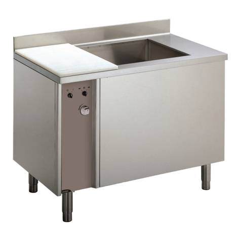
• The vegetable peelers need :
- Connecting to the cold water system near a stop cock
(see § 2.3).
- An adequate evacuation to drains (see § 2.4).
- An electrical power supply (see § 2.5).
• Handling - Transport
The machine is packaged in such a way as to be lifted with a
fork-lift truck. In the event of manual handling of the machine
alone, two persons will be required.
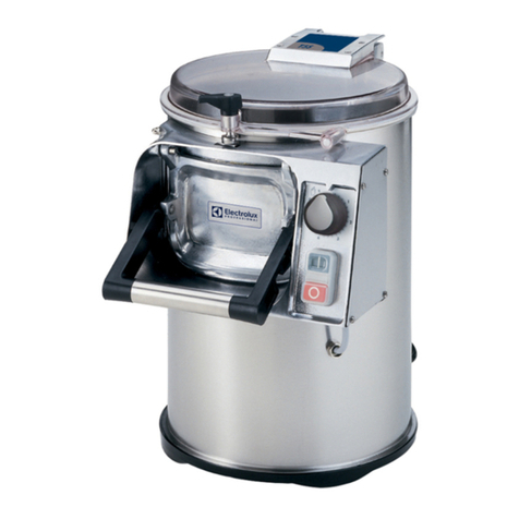
• The peeler 10 Kg or 15kg must be fitted on a support that is
fully stable, horizontal and not resonant (table, unit, sink top, etc.)
of between 400 and 850 mm in height.
• Wastewater drain hose must be installed before use.
• Install as follows :
- Position the evacuation hose for discharge to the rear.
- Remove the 4 screws which attach the base (10 mm spanner),
2.3CONNECTION TO THE WATER MAINS SYSTEM
• The vegetable peelers use the mains pressure and reduced
flow rate.
• In conformity with the sanitary regulations, the machine’s
water inlet is located above the overflow level, at a standardised
distance (overflow device). A stop cock fixed to the wall should
be available and connected via a flexible pipe.
• Connecting to the water supply: (see 2.3)
Procure a sufficiently long length of reinforced hose:
- Fix the tap on the shower head (use a Teflon seal or Loctite
grease proof sealing compound).
- Fix the ½-3/8 reducer coupling with the seal.
- Fit the splined end piece on the hose and tighten the assembly
using the collar.
- Fix the splined end piece on the ½-3/8 reducer coupling with
the seal.
The shower assembly can now be clipped onto the lid of the
machine.
2.3
- 10 and 15 kg vegetable peelers on filter stand :
(for the
assembly of the peeler on the table, refer to the instructions for
assembling the table). Attach the outlet pipe (B), internal diameter
88 mm, to the under side of the tank (A) for collecting the used
water the outlet pipe, using the collar to fasten to the drain.
• Tips :
To drain used water correctly, avoid :
- vertical drops onto inspection chambers (formation of foam),
- sharp angles,
- flattened, deformed or narrow pipes,
- counter slopes, or slopes which are not steep enough.
2.4DRAIN USED WATER AND SEPARATION OF WASTE
2.2a
2.2c
• The waste must be separated according to their size
(peelings, skins, starch, moss, soil, etc.) depending on the
different equipment that is used (see § 3.2).
• Some installations have starch decantation tanks that may
be directly connected. For other installations, we recommend
installing the vegetable peelers on a filter stand in order to
avoid blockages and bad smells.
• Possible installations :
- The 10 kg vegetable peeler without stand (near to a sink) :
Place a filter basket or a strainer next to the peeler.
2
T10E/T15E GB 02 2022
ATTENTION!!
Connection to the electrical power supply must be done according to proper professional practice by a qualified and authorised
person (see current standards and legislation in the country of installation).
If an adapter is used on the socket, a check must be made that the electrical characteristics of this adapter are not lower than
those of the machine.
Do not use multiple plugs
The AC power supply to the machine must comply with the following conditions;
- Maximum voltage variation: ±5%
- Maximum frequency variation: ±1% on a continuous basis, ± 2% over short periods
ATTENTION: the electrical installation must comply (for design, creation and maintenance) with the legal and standard
requirements in the country where used.
- Check that the electric mains voltage, the value shown on the specification plate.
- The machine’s electrical power supply must be protected against voltage surges (short-circuits and excess voltages) by using
fuses or thermal relays of the appropriate gauge relative to the place of installation and machine specifications
ATTENTION: Concerning protection against indirect contact (depending on the type of power supply provided and
connection of the exposed conductive parts to the equipotential protection circuit), refer to point 6.3.3 of EN 60204-1 (IEC
60204-1) with the use of protection devices for automatic shut-off of power in the event of an insulation fault with a TN or
TT, system, or for the IT system, with the use of a permanent insulation or differentials controller for automatic shut-off.
The requirements of IEC 60364-4-41, 413.1 must apply for this protection.
For example: in a TT system, a differential circuit breaker must be installed upline of the power supply, with a suitable power
cut-off (e.g.: 30 mA) on the earthing installation for the place where it is planned to install the machine.
ATTENTION: Failure to comply with these instructions means the customer runs the risk of machine failure and/or accidents
due to direct or indirect contacts.
2.5ELECTRICAL CONNECTION


