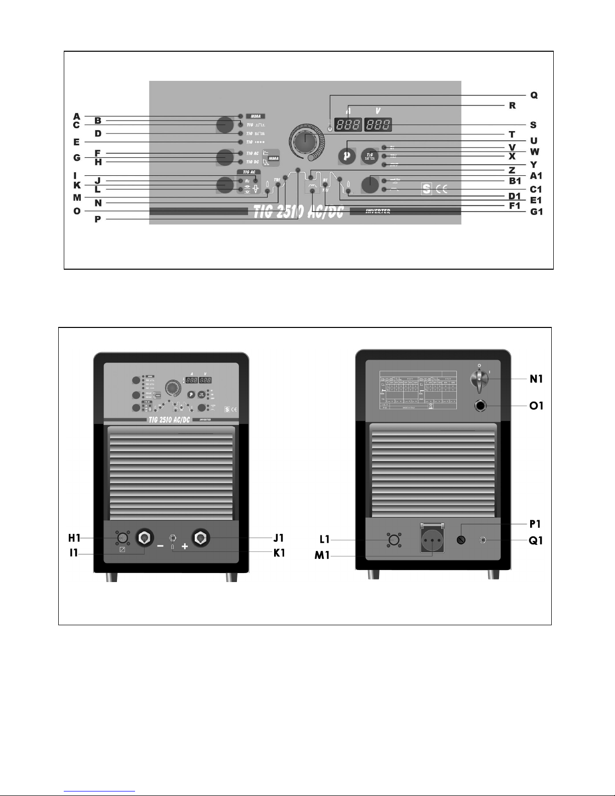
Elettro TIG 2510 User manual

IMANUALE DI ISTRUZIONE PER SALDATRICE AD ARCO ................... Pag. 3
GB INSTRUCTION MANUAL FOR ARC WELDING MACHINE.................... Page 9
DBETRIEBSANLEITUNG FÜR LICHTBOGENSCHWEISSMASCHINEN .... Seite 15
FMANUEL D'INSTRUCTIONS POUR POSTES A SOUDER A L'ARC ........ Page 21
EMANUAL DE INSTRUCCIONES PARA SOLDADORAS DE ARCO .......... Pag. 27
PMANUAL DE INSTRUÇÕES PARA SOLDADORES A ARCO................... Pag. 33
Parti di ricambio e schema elettrico
Spare parts and wiring diagram
Ersatzteile und elektrischer Schaltplan
Pièces de rechanges et schéma électrique
Partes de repuesto y esquema eléctrico
Peças e esquema eléctrico Pagg. Seiten 39

1
2
2

MANUALE DI ISTRUZIONI PER SALDATRICE AD ARCO
IMPORTANTE:
PRIMA DELL’INSTALLAZIONE, DELL’USO O DI
QUALSIASI MANUTENZIONE ALLA SALDATRICE
LEGGERE IL CONTENUTO DI QUESTO MANUALE E
DEL MANUALE “REGOLE DI SICUREZZA PER L’USO
DELLE APPARECCHIATURE” PONENDO PARTICOLARE
ATTENZIONE ALLE NORME DI SICUREZZA.
CONTATTARE IL VOSTRO DISTRIBUTORE SE NON
AVETE COMPRESO COMPLETAMENTE QUESTE
ISTRUZIONI.
1. PREMESSA
Questo apparecchio deve essere utilizzato esclusivamente
per operazioni di saldatura. Non deve essere utilizzato per
scongelare tubi.
E’ inoltre indispensabile tenere nella massima
considerazione il manuale riguardante le regole di
sicurezza.
I simboli posti in prossimità dei paragrafi ai quali si
riferiscono, evidenziano situazioni di massima attenzione,
consigli pratici o semplici informazioni.
Entrambi i manuali devono essere conservati con cura, in
un luogo noto ai vari interessati. Dovranno essere
consultati ogni qual volta vi siano dubbi, dovranno seguire
tutta la vita operativa della macchina e saranno impiegati
per l’ordinazione delle parti di ricambio.
2. DESCRIZIONI GENERALI
2.1 SPECIFICHE
Questa saldatrice è un generatore di corrente continua
costante realizzata con tecnologia INVERTER, progettata
per saldare gli elettrodi rivestiti (con esclusione del tipo
cellulosico) e con procedimento TIG con accensione a
contatto e con alta frequenza.
2.2 SPIEGAZIONE DEI DATI TECNICI RIPORTATI
SULLA TARGA DI MACCHINA
N° Numero di matricola da citare sempre per
qualsiasi richiesta relativa alla saldatrice.
IEC60974-1 La saldatrice é costruita secondo queste
IEC60974-10 norme internazionali.
Cl. A Apparecchiatura per uso industriale e
professionale.
Convertitore statico di frequenza trifase
trasformatore-raddrizzatore.
Caratteristica discendente.
MMA Adatto per saldatura con elettrodi rivestiti.
TIG Adatto per saldatura TIG.
U0Tensione a vuoto secondaria
X Fattore di servizio percentuale. % di 10
minuti in cui la saldatrice può lavorare ad una
determinata corrente senza causare
surriscaldamenti.
I2Corrente di saldatura
U2Tensione secondaria con corrente I2
U1Tensione nominale di alimentazione
3~ 50/60Hz Alimentazione trifase 50 oppure 60 Hz
l1max. E’ il massimo valore della corrente assorbita.
l1eff. E’ il massimo valore della corrente effettiva
assorbita considerando il fattore di servizio.
IP23 Grado di protezione della carcassa che omologa
l’apparecchio per lavorare all’esterno.
Idoneità ad ambienti con rischio accresciuto.
NOTE: La saldatrice è inoltre idonea a lavorare in ambienti con
grado di inquinamento 3. (Vedi IEC 664).
2.3 DESCRIZIONE DELLE PROTEZIONI
2.3.1 Protezione termica
Questo apparecchio è protetto da una sonda di temperatura la
quale, se si superano le temperature ammesse, impedisce il
funzionamento della macchina.
In queste condizioni il ventilatore continua a funzionare ed il
LED Qsi accende.
2.3.2 Protezione di blocco
Questa saldatrice è provvista di diverse protezioni che fermano
la macchina prima che subisca danni. La saldatrice può
funzionare all'interno delle seguenti gamme di tensione:
Per tensione nominale 208/220/230V da 175 a 270V.Per
tensione nominale 400/440V da 340 a 490V
Attenzione: se la tensione di alimentazione non è compresa tra
i valori sopracitati non si accende nessun led e il ventilatore è
alimentato.
Se, all’accensione della macchina, il collegamento delle fasi
non è corretto sul display Rcompaiono 3 punti luminosi
(accensione fissa).
Se, a macchina accesa, la tensione è scesa sotto i 175 V (U1
= 230 V) o 340 V (U1 = 400 V) sul display Rcompare la sigla
E3.
Se, a macchina, accesa, la tensione è salita sopra i 275 V (U1
= 230 V) o 490 V (U1 = 400 V) sul display Rcompare la sigla
E4.
In questi casi spegnere la macchina, ripristinare la giusta
tensione e riaccenderla. Se l'inconveniente è stato risolto la
saldatrice ricomincerà a funzionare.
Se, a macchina accesa, sul display Rcompare la scritta E2
oppure E1 controllare la tensione di alimentazione della
macchina, se questa è corretta la macchina necessita di un
intervento tecnico.
Se viene rilevato un basso livello di acqua per il gruppo di
raffreddamento comparirà la sigla H2O lampeggiante sul
display R.
Se è attivata la funzione password e all’accensione si inserisce
una password errata compare la scritta E72 sul display R.
2.3.3 PASSWORD
Quest’apparecchio è protetto contro l’uso da parte di personale
non autorizzato mediante la richiesta, all’accensione, di una
password.
Per attivare la funzione password, premere il tasto Ue,
mantenendolo premuto, premere il tasto K. Mantenerli premuti
fino a quando sul display Rcompare la sigla H2O, premere
una volta il tasto Uper far comparire la scritta PSS sul display
R. Con la manopola Tmettere su 1, confermare premendo una
volta il tasto U; all’ accensione della macchina comparirà la
scritta PSS sul display R e con la manopola Tinserire la
3

password (visualizzata sul display S) e confermare tenendo
premuto il tasto U.
Se il codice è errato, il generatore si blocca visualizzando
la scritta ERR 72 e per reinserire nuovamente la password
è necessario spegnere e riaccendere il generatore.
Il codice password viene fornito insieme alla macchina e
non si può cambiare.
Si consiglia di custodirlo separatamente e in caso di
smarrimento, contattare il servizio assistenza.
Il generatore esce dalla fabbrica con la funzione PSS su
OFF.
3. INSTALLAZIONE
Controllare che la tensione di alimentazione corrisponda
alla tensione indicata sulla targa dei dati tecnici della
saldatrice.
La portata dell'interruttore magnetotermico o dei fusibili, in
serie alla alimentazione, deve essere uguale alla corrente I1
assorbita dalla macchina.
ATTENZIONE!: Le prolunghe fino a 30m devono essere
almeno di sezione 2,5 mm2.
3.1 MESSA IN OPERA
L'installazione della macchina deve essere fatta da
personale esperto. Tutti i collegamenti debbono essere
eseguiti in conformità alle norme vigenti e nel pieno rispetto
della legge antinfortunistica (norma CEI 26-10- CENELEC
HD 427).
3.2 DESCRIZIONE DELL’APPARECCHIO (fig. 1 e 2)
C - Selettore di procedimento e di modo
Tramite questo pulsante avviene la scelta del procedimento
di saldatura (Elettrodo o TIG) e del modo (2 tempi, 4 tempi
e puntatura).
A ogni pressione di questo pulsante si ottiene una nuova
selezione.
L'accensione dei LED in corrispondenza dei simboli
visualizza la Vostra scelta.
LED A - Saldatura ad elettrodo MMA.
Questa macchina può fondere tutti i tipi di elettrodi rivestiti
escluso il tipo cellulosico.
Con questo procedimento la corrente viene regolata tramite
la manopola Ted è possibile regolare la funzione di "arc
force" (Led H) e di "hot start" (Led F).
LED B - Saldatura a TIG 2 tempi
(manuale)
Premendo il pulsante della torcia la corrente inizia ad
aumentare ed impiega un tempo corrispondente allo "slope
up" LED O acceso, preventivamente regolato, per
raggiungere il valore regolato con la manopola T. Quando
si lascia il pulsante la corrente inizia a diminuire ed impiega
un tempo corrispondente allo "slope down" LED E1 acceso,
preventivamente regolato, per ritornare a zero.
LED D - Saldatura a TIG 4 tempi
(automatico)
Questo programma differisce dal precedente perché sia
l'accensione che lo spegnimento vengono comandati
premendo e rilasciando il pulsante della torcia TIG.
LED E - Saldatura a TIG puntatura
(manuale)
Dopo avere scelto la corrente di saldatura LED Pe il tempo di
puntatura LED G1 tramite il selettore K, impostarne i valori
tramite la manopola T. Si esegue questo modo di saldatura
solo se viene selezionata l’accensione con alta frequenza LED
B1 acceso. In questa modo di saldatura l'operatore preme il
pulsante della torcia, si accende l'arco, e dopo il tempo di
puntatura regolato, l'arco si spegne automaticamente. Per
eseguire il punto successivo è necessario rilasciare il pulsante
torcia e poi ripremerlo.
W - Selettore di modo 4 tempi
Tramite questo pulsante avviene la scelta del modo di
saldatura 4 tempi con due livelli di corrente, 4 tempi con tre
livelli di corrente e 4 tempi speciale SWP.
A ogni pressione di questo pulsante si ottiene una nuova
selezione.
L'accensione dei LED in corrispondenza ai simboli visualizza la
Vostra scelta.
LED V - Saldatura a TIG 4 tempi con due livelli
di corrente (automatico bilevel)
Prima di accendere l'arco impostare i due livelli di corrente.
Primo livello: premere il tasto Kfino ad accendere il LED Pe
regolare la corrente principale con la manopola T.
Secondo livello: premere il tasto Kfino ad accendere il LED F1
e regolare la corrente con la manopola T.
Dopo l'accensione dell'arco la corrente inizia ad aumentare
ed impiega un tempo corrispondente allo "slope up" (LED O
acceso), preventivamente regolato, per raggiungere il valore
regolato con manopola T. Il LED Psi accende e il display Rla
visualizza.
Se durante la saldatura vi è la necessità di diminuire la
corrente senza spegnere l'arco (per esempio cambio del
materiale d'apporto, cambio di posizione di lavoro, passaggio
da una posizione orizzontale ad una verticale ecc.…) premere
e rilasciare immediatamente il pulsante torcia, la corrente si
porta al secondo valore selezionato, il LED F1 si accende e P
si spegne.
Per tornare alla precedente corrente principale ripetere l'azione
di pressione e di rilascio del pulsante torcia, il LED P si
accende mentre il LED F1 si spegne. In qualsiasi momento si
voglia interrompere la saldatura premere il pulsante torcia per
un tempo maggiore di 0,7 secondi poi rilasciarlo, la corrente
comincia a scendere fino al valore di zero nel tempo di "slope
down", preventivamente stabilito (LED E1 acceso).
Durante la fase di "slope down", se si preme e si rilascia
immediatamente il pulsante della torcia, si ritorna in "slope up"
se questo è regolato ad un valore maggiore di zero,
oppure alla corrente minore tra i valori regolati.
N.B. il termine "PREMERE E RILASCIARE IMMEDIATA-
MENTE" fa riferimento ad un tempo massimo di 0,5 sec.
LED X - Saldatura a TIG 4 tempi con tre livelli
di corrente (automatico trilevel)
Per impostare le tre correnti di saldatura agire come segue:
Premere il selettore Kfino ad accendere il LED Pquindi
regolare il valore della massima corrente con la manopola T.
Premere il selettore Kfino ad accendere il LED F1 quindi
regolare il valore della corrente intermedia con la manopola T.
Premere il selettore Kfino ad accendere il LED Nquindi
regolare il valore della corrente di accensione con la manopola
T.
La logica di funzionamento è quella descritta precedentemente
per la saldatura con doppio livello di corrente LED V.
4

LED Y - Saldatura a TIG 4 tempi
programma speciale
Per accendere l'arco premere il pulsante della torcia e
tenendolo premuto, la corrente inizia ad aumentare con un
incremento fisso. Se si rilascia il pulsante la corrente sale
immediatamente al valore di saldatura LED P. Per
terminare la saldatura premere il pulsante torcia e
mantenendolo premuto la corrente inizia a diminuire con un
decremento fisso. Se si rilascia il pulsante la corrente si
azzera istantaneamente.
A1 - Selettore accensione con alta frequenza e
arco pulsato, on-off
Tramite questo pulsante avviene la scelta del tipo di
accensione (con alta frequenza o per contatto) e del modo
continuo o con arco pulsato. A ogni pressione di questo
pulsante si ottiene una nuova selezione.
L'accensione dei LED in corrispondenza dei simboli
visualizza la Vostra scelta
LED B1 - Accensione con alta frequenza o
per contatto.
Quando il LED è spento per accendere l'arco premere il
pulsante torcia e toccare con l'elettrodo di tungsteno il
pezzo da saldare e rialzarlo. Il movimento deve essere
deciso e rapido.
Quando il LED è acceso per accendere l'arco premere il
pulsante torcia, una scintilla pilota di alta
tensione/frequenza accenderà l'arco.
LED L1 - Arco pulsato on-off
Quando il LED è acceso il modo arco pulsato è attivato.
Da 0,16 fino a 1,1Hz di frequenza di pulsazione il display S
visualizza alternativamente la corrente di picco (principale)
e la corrente di base
I LED P e Z si accendono alternativamente; oltre 1,1Hz il
display S visualizza la media delle due correnti e i LED P e
Z restano entrambi accesi.
Quando il LED è spento è attivo il modo continuo.
G - Selettore modo TIG AC o DC.
LED F – Saldatura TIG, modalità AC /
Saldatura MMA, Hot Start
In modo TIG, quando il LED è acceso si è in modalità AC
(corrente alternata).
Se si è in modo MMA, si seleziona l’Hot Start; sul display S
è visualizzato il tempo (espresso in secondi) in cui la
saldatrice eroga una sovracorrente per migliorare
l’accensione dell’elettrodo. La regolazione avviene tramite
la manopola T.
LED H – Saldatura TIG, modalità DC /
Saldatura MMA, Arc Force
In modo TIG, quando il LED è acceso, si è in modalità DC
(corrente continua).
Se si è in modalità MMA, si seleziona l’Arc Force; è una
percentuale della corrente di saldatura. Il display Sne
visualizza il valore che si regola con la manopola T. In pratica
questa sovracorrente favorisce il trasferimento delle gocce di
metallo fuso.
K - Selettore parametri di saldatura MMA e TIG
Premendo questo pulsante si illuminano in successione i LED.
Attenzione si illumineranno solo i LED che si riferiscono al
modo di saldatura scelto; es. in saldatura TIG continuo non si
illuminerà il LED G1 che rappresenta la frequenza di
pulsazione.
Ogni LED indica il parametro che può essere regolato tramite
la manopola T durante il tempo di accensione del LED stesso.
Dopo 5 secondi dall'ultima variazione il LED interessato si
spegne e viene indicata la corrente di saldatura principale e si
accende il corrispondente LED P.
LED J – Frequenza AC
Regola la frequenza della corrente alternata da 50 a 150Hz.
LED L – Bilanciamento dell’onda.
Regola la pulizia da –8 a 0 o la penetrazione da 0 a 8.
LED I – Scelta del diametro dell’elettrodo in AC
Regola la partenza in funzione del diametro dell’elettrodo.
LED M
Pre gas. Regola Il tempo di uscita del gas prima dell'inizio della
saldatura (0,05-2,5 sec.)
LED N
Led corrente di inizio saldatura. E' una percentuale della
corrente di saldatura LED P in modo trilevel.
LED O
Slope up. E' il tempo in cui la corrente, partendo dal minimo,
raggiunge il valore di corrente impostato. (0-10 sec.)
LED P
Corrente di saldatura principale.
LED Z
Corrente di base in modo arco pulsato.
LED G1
Frequenza di pulsazione da 0,16 a 550 Hz.
I tempi di base e di picco sono uguali.
5

LED F1
Secondo livello di corrente in modo bilevel.
LED E1
Slope down. E' il tempo in cui la corrente raggiunge il
minimo e lo spegnimento dell'arco. (0-10 sec.)
LED D1
Post gas. Regola il tempo di uscita del gas al termine della
saldatura. (0-30 sec.)
T - Manopola.
Regola la corrente di saldatura LED P.
Inoltre in abbinamento al pulsante K è possibile regolare
altri parametri di saldatura.
LED Q - Protezione termica.
Si accende quando l'operatore supera il fattore di servizio o
di intermittenza percentuale ammesso per la macchina e
blocca contemporaneamente l'erogazione di corrente.
N.B. In questa condizione il ventilatore continua a
raffreddare il generatore.
S – Display
Normalmente visualizza la tensione d'arco in relazione al
processo di saldatura in atto.
Nell'impostazione del funzionamento del gruppo di
raffreddamento ne visualizza lo stato.
R – Display
Visualizza la corrente di saldatura e le impostazioni
selezionate con il pulsante K e regolate con la manopola T.
6
Nelle procedure di blocco (vedi 2.3.2) della macchina
visualizza:
-tre punti lampeggianti o accesi di continuo.
-le sigle E1 E2 E3 E4
-la sigla H2O.
U - Selettore programmi in memoria.
Seleziona e memorizza i programmi.
La saldatrice ha la possibilità di memorizzare nove
programmi di saldatura P01…..P09 e di poterli richiamare
tramite questo pulsante. Inoltre è disponibile un programma
lavoro PL .
Selezione
Premendo brevemente questo pulsante viene visualizzato
sul display R il numero del programma successivo a quello
in cui si sta lavorando. Se questo non è stato memorizzato
la scritta sarà lampeggiante, contrariamente sarà fissa.
Memorizzazione
Una volta selezionato il programma, premendo per un tempo
maggiore di 3 secondi, si memorizzano i dati.
A conferma di questo, il numero del programma, visualizzato
sul display R, terminerà di lampeggiare
H1 –CONNETTORE 10 POLI.
A questo connettore vanno collegati i
seguenti comandi remoti:
a) pedale
b) torcia con pulsante di start
c) torcia con potenziometro
d) torcia con up/down
e) comando a distanza ecc…
E' disponibile tra i pin 3 e 6 un contatto pulito
che segnala la accensione dell'arco (5A 230V).
K1 –Raccordo ¼ gas.
Vi si connette il tubo gas della torcia di saldatura TIG.
I1
Morsetto di uscita negativo (-).
J1
Morsetto di uscita positivo (+).
N1 –Interruttore.
Accende e spegne la macchina.
Q1 - Raccordo ingresso gas.
O1 - Cavo di alimentazione.
M1 – Presa
A cui collegare il gruppo di raffreddamento.
Attenzione: Potenza max: 250VA - Ampere: 2.
Non collegare utensili quali smerigliatrici o similari.
P1 - Fusibile

L1 – Connettore
Connettore a 10 poli a cui va collegato il cavetto del gruppo
di raffreddamento.
3.3 NOTE GENERALI
Prima dell'uso di questa saldatrice leggere attentamente le
norme CEI 26/9 - CENELEC HD 407 e CEI 26.11 -
CENELEC HD 433 inoltre verificare l'integrità
dell'isolamento dei cavi, delle pinze porta elettrodi, delle
prese e delle spine e che la sezione e la lunghezza dei cavi
di saldatura siano compatibili con la corrente utilizzata.
3.4 SALDATURA DI ELETTRODI RIVESTITI (MMA)
- Questa saldatrice è idonea alla saldatura di tutti i tipi di
elettrodi ad eccezione del tipo cellulosico (AWS 6010).
- Assicurarsi che l'interruttore N1 sia in posizione 0, quindi
collegare i cavi di saldatura rispettando la polarità
richiesta dal costruttore di elettrodi che andrete ad
utilizzare e il morsetto del cavo di massa al pezzo nel
punto più vicino possibile alla saldatura assicurandosi che
vi sia un buon contatto elettrico.
- Non toccare contemporaneamente la torcia o la pinza
porta elettrodo ed il morsetto di massa.
- Accendere la macchina mediante l'interruttore N1.
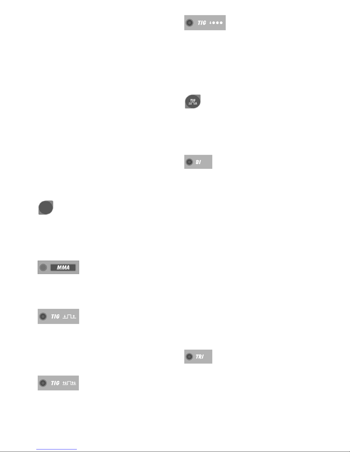
- Selezionare, premendo il pulsante C, il procedimento
MMA, LED AAcceso.
- Regolare la corrente in base al diametro dell'elettrodo, alla
posizione di saldatura e al tipo di giunto da eseguire.
- Terminata la saldatura spegnere sempre l'apparecchio e
togliere l'elettrodo dalla pinza porta elettrodo.
Se si vogliono regolare le funzioni di Hot-start LED F e di
Arc force LED Hvedere il paragrafo precedente.
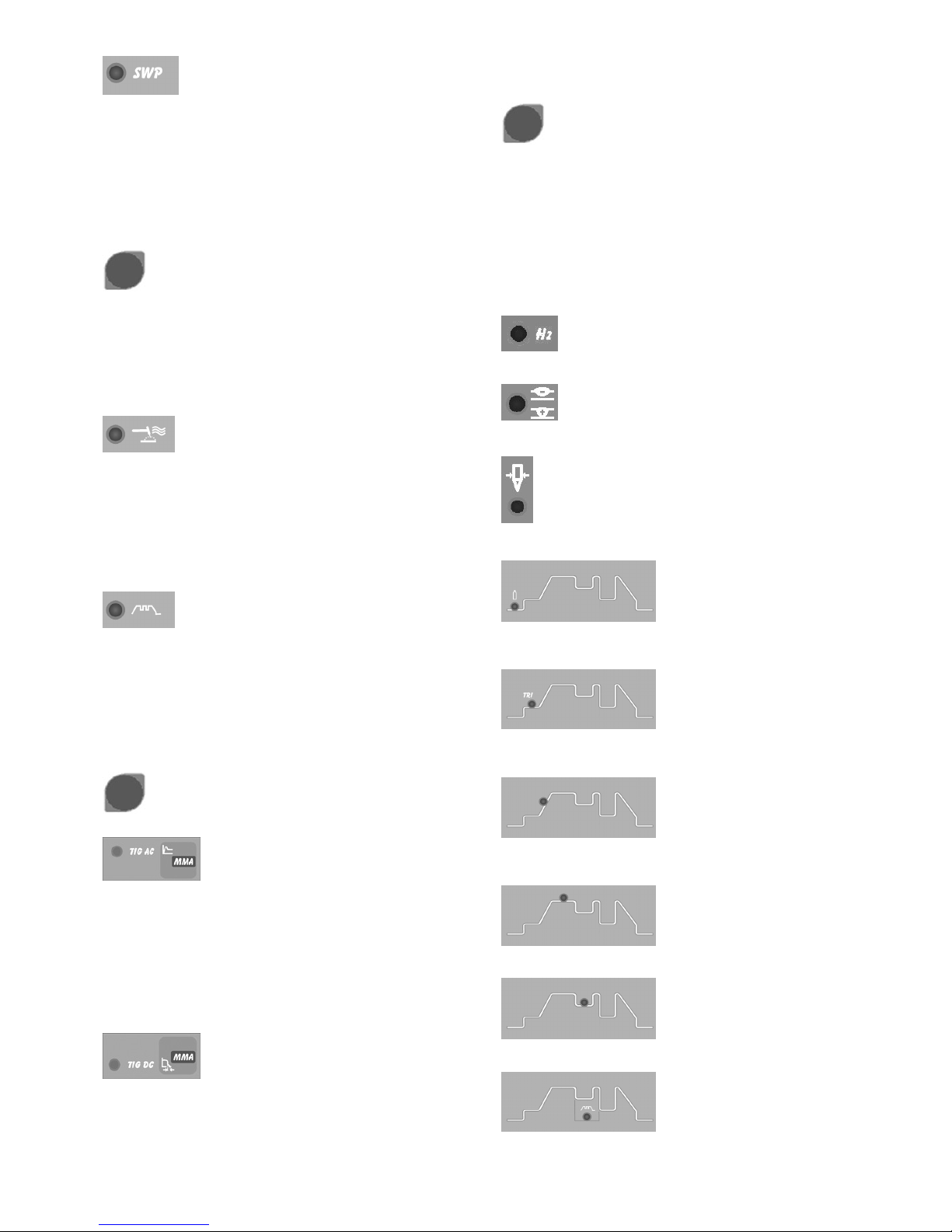
3.5 SALDATURA TIG
Questa saldatrice è idonea a saldare con procedimento
TIG DC l'acciaio inossidabile, il ferro, il rame e con
procedimento TIG AC l’alluminio, l’ottone e il magnesio.
Collegare il connettore del cavo di massa al polo positivo
(+) della saldatrice e il morsetto al pezzo nel punto più
vicino possibile alla saldatura assicurandosi che vi sia un
buon contatto elettrico.
Collegare il connettore di potenza della torcia TIG al polo
negativo (-) della saldatrice.
Collegare il connettore di comando della torcia al
connettore H1 della saldatrice.
Collegare il raccordo del tubo gas della torcia al raccordo
K1 della macchina ed il tubo gas proveniente dal riduttore
di pressione della bombola al raccordo gas Q1.
Se si utilizza una torcia raffreddata ad acqua utilizzare il
gruppo di raffreddamento.
Dopo avere riempito di liquido refrigerante il serbatoio
collegare la spina del cavo rete alla presa M1 della
saldatrice, quindi collegare il connettore maschio volante
10 poli al connettore L1.
Accendere la macchina.
Non toccare parti sotto tensione e i morsetti di uscita
quando l'apparecchio è alimentato.
Alla prima accensione della macchina selezionare il modo
mediante i pulsanti C, G, We A1 e i parametri di saldatura
mediante il tasto Ke la manopola Tcome indicato al
paragrafo 3.2.
Il flusso di gas inerte deve essere regolato ad un valore (in
litri al minuto) di circa 6 volte il diametro dell'elettrodo.
Se si usano accessori tipo il gas-lens la portata di gas può
essere ridotta a circa 3 volte il diametro dell'elettrodo. Il
diametro dell'ugello ceramico deve avere una dimensione
da 4 a 6 volte il diametro dell'elettrodo.
Normalmente il gas più usato è l'ARGON perché ha un costo
minore rispetto agli altri gas inerti, ma possono essere usate
anche miscele di ARGON con un massimo del 2%
IDROGENO per la saldatura dell'acciaio inossidabile e ELIO o
miscele di ARGON-ELIO per la saldatura del rame. Queste
miscele aumentano il calore dell'arco in saldatura ma sono
molto più costose.
Se si usa gas ELIO aumentare litri al minuto fino a 10 volte il
diametro dell'elettrodo (Es. diametro 1,6 x10= 16 l/min. di Elio).
Usare vetri di protezione D.I.N. 10 fino a 75A e D.I.N. 11 da
75A in poi.
3.5.1 GRUPPO DI RAFFREDDAMENTO (optional art.
560101)
Se si utilizza una torcia raffreddata ad acqua utilizzare il
gruppo di raffreddamento.
Per selezionare il modo di funzionamento del gruppo di
raffreddamento agire come segue:
1. Selezionare un qualsiasi procedimento TIG.
2. Premere il tasto Ue mantenendolo premuto premere il
tasto K. Mantenerli premuti fino a quando sul display R
compare la sigla H2O.
3. Selezionare il funzionamento tramite la manopola T
1 = Gruppo spento,
2 = Funzionamento in continuo,
3 = Funzionamento in automatico.
Per uscire dalla selezione premere brevemente il tasto U.
N.B. Per "Funzionamento automatico" si intende che il gruppo
di raffreddamento si mette in moto alla pressione del pulsante
torcia e smette di funzionare dopo circa 2 minuti dal rilascio del
pulsante torcia.
Attenzione! Se selezionata la saldatura in elettrodo, il
raffreddamento non è acceso e non è selezionabile. E' normale
che alla accensione della macchina il display Rvisualizzi, in
modo lampeggiante, la sigla H2O.
3.6 MEMORIZZAZIONE
E' possibile memorizzare solo dopo avere saldato.
Il pulsante U, premuto brevemente, effettua una scelta;
premuto per un tempo maggiore di 3 secondi, effettua una
memorizzazione.
Ad ogni accensione, la macchina presenta sempre l'ultima
condizione utilizzata in saldatura.
3.6.1 Memorizzare i dati del programma PL
Utilizzando la macchina per la prima volta.
Alla accensione della macchina il display visualizza la sigla PL
questa, dopo 5 secondi, scompare e viene visualizzata una
corrente di lavoro. Seguire le indicazioni dei paragrafi 3.2 e 3.5
quindi, per memorizzare i dati nel programma P01, procedere
nel seguente modo:
· Premere brevemente il pulsante Ucomparirà la scritta P01
lampeggiante.
· Premere il pulsante Uper un tempo maggiore di 3 secondi
fino a che la sigla P01 smetta di lampeggiare, a questo punto
la memorizzazione è avvenuta.
· Ovviamente se invece di memorizzare nel programma P01 si
vuole memorizzare in un programma diverso si premerà il
pulsante Uin maniera breve tante volte quante necessarie
per visualizzare il programma desiderato. Alla riaccensione
della macchina viene visualizzato P01.
IL PULSANTE U PREMUTO BREVEMENTE EFFETTUA UNA
SCELTA, PREMUTO PER UN TEMPO MAGGIORE DI 3
SECONDI EFFETTUA UNA MEMORIZZAZIONE.
3.6.2 Memorizzare da un programma libero
L'operatore può modificare e memorizzare un programma
scelto procedendo nel seguente modo:
· Premere il pulsante Uin modo breve e scegliere il numero di
programma desiderato.
I programmi liberi hanno la sigla lampeggiante.
7

8
· Premere i pulsanti C, G, We A1 e scegliere il
procedimento e il modo di saldatura (paragrafo 3.2).
· Girare la manopola Ted impostare la corrente di
saldatura.
Se è stato scelto il procedimento TIG, attivare il LED D1
(post gas) tramite il pulsante Ke regolare tramite la
manopola Til valore desiderato (paragrafo 3.2.)
Se dopo queste regolazioni, necessarie per saldare, si
vogliono regolare i tempi di "slope" o altro agire come
descritto al paragrafo 3.2.
Eseguire una saldatura anche breve e decidere dove
memorizzare
Per memorizzare nel programma scelto precedentemente,
premere il pulsante Uper più di 3 secondi fino a che il
numero smette di lampeggiare.
Per memorizzare in un programma diverso, fare la scelta
premendo brevemente il pulsante Uquindi premere il
pulsante Uper più di 3 secondi.
3.6.3 Memorizzare da un programma memorizzato
Partendo da un programma già memorizzato l'operatore
può modificare i dati in memoria per aggiornare il
programma stesso o per trovare nuovi parametri da
memorizzare in un altro programma.
3.6.3.1 Aggiornare
· Dopo avere acceso la macchina selezionare i parametri
da modificare e modificarli.
· Eseguire una saldatura anche breve.
· Premere per un tempo maggiore di 3 secondi il tasto U
fino alla conferma della memorizzazione (sigla del
programma da lampeggiante a continua).
3.6.3.2 Memorizzare in un nuovo programma
· Dopo avere acceso la macchina selezionare i parametri
da modificare e modificarli.
· Eseguire una saldatura anche breve.
· Premere brevemente il selettore Ufino alla
visualizzazione del programma da Voi desiderato.
· Premere di continuo il tasto Ufino alla conferma della
memorizzazione (sigla del programma da lampeggiante a
continua).
4. COMANDI A DISTANZA
Per la regolazione della corrente di saldatura a questa
saldatrice possono essere connessi i seguenti comandi a
distanza:
Art. 570008 Comando a pedale (usato in saldatura TIG)
Art. 535805 Torcia TIG UP/DOWN.
Art. 535807 Torcia TIG UP/DOWN raffreddata ad acqua.
Art. 530330 + Art. 570006 (usato in saldatura MMA)
Art. 363307 Connessione per collegare contemporanea-
mente la torcia e il comando a pedale. Con questo
accessorio l’Art. 570008 può essere utilizzato in qualsiasi
modo di saldatura TIG.
I comandi che includono un potenziometro regolano la
corrente di saldatura dal minimo fino alla massima
corrente impostata con la manopola T.
I comandi con logica UP/DOWN regolano dal minimo al
massimo la corrente di saldatura.
Le regolazioni dei comandi a distanza sono sempre attive
nel programma PL mentre in un programma memorizzato
non lo sono.

INSTRUCTION MANUAL FOR ARC WELDING MACHINES
IMPORTANT: READ THIS MANUAL AND THE “SAFETY
RULES” MANUAL CAREFULLY BEFORE INSTALLING,
USING, OR SERVICING THE WELDING MACHINE,
PAYING SPECIAL ATTENTION TO SAFETY RULES.
CONTACT YOUR DISTRIBUTOR IF YOU DO NOT FULLY
UNDERSTAND THESE INSTRUCTIONS.
1. PRECAUTIONS
This machine must be used for welding only. It must not be
used to defrost pipes.
It is also essential to pay special attention to the "SAFETY
RULES" Manual.
The symbols next to certain paragraphs indicate points
requiring extra attention, practical advice or simple
information.
This MANUAL and the "SAFETY RULES" MANUAL must be
stored carefully in a place familiar to everyone involved in
using the machine. They must be consulted whenever doubts
arise and be kept for the entire lifespan of the machine; they
will also be used for ordering replacement parts.
2. GENERAL DESCRIPTIONS
2.1 SPECIFICATIONS
This welding machine is a constant current power source
built using INVERTER technology, designed to weld covered
electrodes (not including cellulosic) and for TIG procedures,
with contact starting and high frequency.
2.2 EXPLANATION OF THE TECHNICAL
SPECIFICATIONS LISTED ON THE MACHINE
PLATE.
N°. Serial number, which must be indicated on any
type of request regarding the welding machine.
IEC60974-1 The welding machine is manufactured
IEC60974-10 according to this international standards.
Cl. A Machine for professional and industrial use.
Tri-phase static transformer-rectifier frequency
converter.
Drooping-characteristic.
MMA Suitable for welding with covered electrodes.
TIG Suitable for TIG welding.
U0Secondary open-circuit voltage
X Duty cycle percentage. % of 10 minutes during
which the welding machine may run at a
certain current without overheating.
I2Welding current
U2Secondary voltage with current I2
U1Rated supply voltage
3- 50/60Hz 50- or 60-Hz tri-phase power supply
I1 max. This is the maximum value of the absorbed
current.
I1eff. This is the maximum value of the actual current
absorbed, considering the duty cycle.
IP23 Protection grade of the housing, approving the
equipment as suitable for use outdoors.
Suitable for hazardous environments.
NOTES: the welding machine has also been designed for use in
environments with a pollution rating of 3. (See IEC 664).
2.3 DESCRIPTION OF PROTECTIVE DEVICES
2.3.1 Thermal protection
This machine is protected by a temperature probe, which
prevents the machine from operating if the allowable
temperatures are exceeded. Under these conditions the fan
keeps running and the LED Qlights.
2.3.2 Block protections
This welding machine is equipped with various safety devices
that stop the machine before it can suffer damage.
The welding machine may operate within the following voltage
ranges:
For rated voltage 208/220/230V, from 175 to 270V
For rated voltage 400/440V, from 340 to 490V
Caution: if the supply voltage does not fall between the above
values, no LED will light and the fan is powered.
If the phases are not properly connected, 3 light points will
appear (steadily lit) on the display Rwhen the machine is
started.
If, with the machine on, the voltage falls below 175 V (U1 =
230V) or 340 V (U1 = 400V), the display Rwill show the
abbreviation E3.
If, with the machine on, the voltage rises above 275 V (U1 =
230V) or 490 V (U1 = 400V), the display Rshows the
abbreviation E4.
In this case turn off the machine, restore the proper voltage and
restart. If the problem has been corrected, the welding machine
will begin operating again.
If, with the machine on, the display Rshows the message E2 or
E1, check the supply voltage of the machine; if it is correct, the
machine requires technical service.
If a low water level is detected for the cooling unit the
abbreviation H2O flashes on the display R.
If the Password function is activated and you enter a wrong
password when logging in, the message “E72” appears on the R
display.
2.3.3 PASSWORD
This equipment is protected against the use on behalf of
unauthorised personnel through the request, on ignition, of a
password.
To activate the Password function, press the Ukey and then,
holding it down, press the Kkey. Hold both keys down until the
message H2O is displayed on display R, then press the Ukey
once to bring the message PSS to the R display. By means of
the knob Tput on 1, confirm by pressing the key Uonce; when
igniting the machine, the writing PSS will appear on display R
and with knob Tinsert the password (displayed on display S)
and confirm by holding the U key down.
If the code is incorrect, the generator will block, displaying the
writing ERR 72 and to insert the password again, it is necessary
to switch the generator off and on.
The password code is supplied together with the machine and
cannot be changed.
9

It is recommended to keep it separate, and in case of loss,
contact the after-sales assistance.
The generator leaves the factory with the PSS function on
OFF.
3. INSTALLATION
Make sure that the supply voltage matches the voltage
indicated on the specification plate of the welding machine.
The capacity of the overload cut-out switch or fuses installed
in series with the power supply must be equivalent to the
absorbed current I1of the machine.
WARNING! Extension cords of up to 30m must have a cross-
section of at least 2.5 mm2.
3.1 START-UP
Only skilled personnel should install the machine. All
connections must be carried out according to current
regulations, and in full observance of safety laws (regulation
CEI 26-10 -CENELEC HD 427).
3.2 DESCRIPTION OF THE EQUIPMENT (Pict. 1 and 2).
C – Procedure and mode selector switch
This push-button selects the welding procedure (MMA or
TIG) and mode (2-step, 4-step and spot welding).
The selection changes each time the button is pressed.
The LEDs light next to the various symbols to display your
choice.
LED A – MMA (Manual Metal Arc)
welding.
This machine can melt all types of coated electrodes, except
for cellulose.
With this process the current is adjusted using the knob T,
and it is possible to adjust the "arc force" (LED H) and "hot
start" function (LED F).
LED B – 2-step TIG welding (manual)
When the torch trigger is pressed, the current begins to
increase over the previously set “slope up” time (OLED on),
until it reaches the value set by means of the Tknob. When
the trigger is released, the current begins to drop over the
previously set “slope down” time (E1 LED on), until it goes
back to zero.
LED D – 4-step TIG welding
(automatic)
This program differs from the previous one in that the arc is
both started and extinguished by pressing and releasing the
TIG torch trigger.
LED E – TIG spot-welding LED
(manual)
After selecting the welding current (LED P) and the spot
welding time (LED G1) using the selector switch K, set the
values using the knob T.
This welding mode is to be used only if start-up with high
frequency is selected (LED B1 lit). In this welding mode, the
operator presses the torch trigger, the arc lights, and after the
set spot welding time the arc shuts off automatically. To do
the next spot, you must therefore release the torch trigger
and press it again.
W – 4-step mode selector switch
This push-button selects the welding mode: 4-step with dual
current level, 4-step with with three levels of current and 4-step
SWP special program.
The selection changes each time the button is pressed.
The LEDs light next to the various symbols to display your
choice.
LED V - 4-step TIG welding with dual current
level, (automatic bilevel).
Set the two current levels before lighting the arc:
First level: press the Kkey until the LED Plights, and adjust the
main current using the knob T.
Second level: press the Kkey until the LED F1 lights, and
adjust the main current using the knob T.
When the torch trigger is pressed, the current begins to
increase over the previously set "slope up" time (LED Olit), until
it reaches the value set by means of the knob T. The LED P
lights and appears on the display R.
Should it be necessary to reduce the current during welding,
without shutting of the arc (for instance when changing the
welding material or working position, moving from horizontal to
upright, etc.…), press and immediately release the torch trigger:
the current will switch to the second value selected, the LED F1
will light and Pwill go off.
To return to the previous main current, press and release the
torch trigger once again. The LED Pwill light, and the LED F1
will go off. To stop welding at any time, simply hold down the
torch trigger for more than 0.7 seconds, then release. The
current begins to fall to zero within the previously set "slope
down" time interval (LED E1 lit).
If you press and immediately release the torch trigger during the
"slope down" phase, you will return to "slope up" if it is set to
greater than zero, or to the lesser current value of those set.
NOTE: The expression "PRESS AND IMMEDIATELY
RELEASE" refers to a maximum time of 0.5 seconds.
LED X - 4-step TIG welding with three levels of
current (automatic trilevel).
To set the three welding currents, proceed as follows:
Press the selector switch Kuntil the LED Plights, then adjust
the maximum current value using the knob T.
Press the selector switch Kuntil the LED F1 lights, then adjust
the intermediate current value using the knob T.
Press the selector switch Kuntil the LED Nlights, then adjust
the starting current value using the knob T.
The operating logic is the same as previously described for
welding with dual current level LED V.
LED Y - 4-step TIG welding with special
program
To light the arc, press the torch trigger and hold it down; the
current begins to increase at a fixed rate. If the torch trigger is
released, the current immediately rises to the welding value
(LED P). To stop welding, press the torch trigger and hold it
down; the current begins to drop at a fixed rate. The current
immediately returns to zero if the trigger is released.
LED A1 - Selector switch for high frequency ignition
and pulsed arc mode, on-off
This push-button selects the ignition type (with high frequency
or by contact) and the continuous or pulsed arc mode. The
selection changes each time the button is pressed.
10

The LEDs light next to the various symbols to display your
choice.
LED B1 - Ignition with high frequency or by
contact.
When the LED is off, to start the arc press the torch trigger
and touch the tungsten electrode to the workpiece, then lift it.
This move must be quick and sharp.
When the LED is on, to start the arc, press the torch trigger:
a high voltage/frequency pilot spark will start the arc.
LED L1 - Pulsed arc, on-off
When the LED is on, the pulsed arc mode is activated.
From a pulse frequency of 0.16 to 1.1Hz, the S display
alternately shows the peak (main) current and the base
current
The P and Z LEDs light alternately: beyond 1.1 Hz the S
display shows the mean of the two currents and the P and Z
LEDs both remain on.
When the LED is off, the continuous mode is activated.
G - TIG AC or DC Mode Selector.
LED F – TIG Welding, AC Mode / MMA
Welding, Hot Start
In the TIG mode, the machine is in the AC (alternating
current) mode when the LED is on.
If you are in the MMA mode, select Hot Start. The Sdisplay
shows how much time (in seconds) it takes for the welding
machine to provide an overcurrent to improve the electrode
ignition. Adjustments can be made by using the T knob.
LED H – TIG Welding, DC Mode / MMA
Welding, Arc Force
In the TIG mode, the machine is in the DC (direct current)
mode when the LED is on.
If you are in the MMA mode, select Arc Force (a percentage
of the welding current). Its value is shown on the Sdisplay
and can be adjusted by using the T knob. In fact, this
overcurrent makes the transfer of molten metal droplets
easier.
K – MMA and TIG welding parameters selector
switch
Pressing this button will light the LEDs in sequence:
Warning: only those LEDs which refer to the chosen
welding mode will light; e.g. in continuous TIG welding the
G1 LED, representing the pulse frequency, will not light.
Each LED indicates the parameter, which may be adjusted
via the T knob during the lighting time of the LED.
5 seconds after the last variation, the LED involved will light
off; the main welding current will then be displayed and the
corresponding PLED will light.
LED J – AC frequency
Adjust the AC frequency from 50 to 150Hz.
LED L – Wave balance.
Adjust the cleaning from –8 to 0 or the penetration from 0 to 8.
LED I – Selection of the electrode diameter in AC
mode
Adjust the start-up according to the diameter of the electrode.
LED M
Pre-gas LED. Adjustment 0.05-2.5 seconds. Gas output time
before starting welding.
LED N
Welding start current LED. This is a percentage of the welding
current LED Pin three levels mode.
LED O
Slope up LED. This is the time in which the current, starting
from the minimum, reaches the set current value. (0-10 sec.)
LED P
Main welding current LED .
LED Z
Base current in pulsed arc mode.
LED G1
Pulse frequency LED (0.16-550 Hz).
The peak and base times are equal.
LED F1
Second level of current in dual level mode.
LED E1
Slope down. This is the time during which the current reaches
its minimum value and the arc is extinguished (0-10 sec.).
LED D1
Post gas. Adjusts the gas flow time at the end of welding (0-30
sec.).
11

T - Knob
Adjusts the welding current - LED P.
In addition, combined with the K push-button, it adjusts other
welding parameters
LED Q - Thermal protection.
It lights when the operator exceeds the duty cycle or
percentage intermittence allowed for the machine and
simultaneously stops the current output.
N.B. Under this condition the fan goes on cooling the
power source.
S – Display
Normally displays the arc voltage in relation to the current
welding process.
When setting the cooling unit operation, it displays the status
of this unit.
R – Display
Displays the welding current and the settings selected by
means of the push-button Kand adjusted via the knob T.
12
In the machine blocking procedures (see 2.3.2), it displays:
-Three flashing or steadily lit points
-The abbreviations E1 E2 E3 E4
-The abbreviation H2O.
U - Selector switch for programs in memory.
Selects and saves the programs in memory.
The welding machine can save nine welding programs
P01…..P09 and call them up via this button. A working
program PL is also available.
Selecting
When this push-button is pressed briefly, the R display shows
the program number next to the one in use. If this has not
been saved, the message will flash, otherwise it remains
steady.
Saving
Once the program has been selected, hold down for more
than 3 seconds to save the data in memory.
To confirm this, the program number on the R display will
stop flashing
H1 – 10-pin connector
The following remote controls are to be connected to this
connector:
a) foot control
b) torch with start button
c) torch with potentiometer
d) torch with up/down
e) remote control, etc.
A clean contact is available between pins 3 and 6 to signal
when the arc is lit (5A 230V).
K1 – 1/4 GAS FITTING
This is where the gas hose of the TIG welding torch is to be
connected.
I1
Negative output terminal (-)
J1
Positive output terminal (+)
N1 – Switch
Turns the machine on and off
Q1 - Gas intake fitting
O1 - Power supply cable.
M1 – Socket
To which to connect the cooling unit.
Caution: Max. power: 250VA - Amps: 2.
Do not connect tools such as polishers or similar
P1 - Fuse
L1 – Connector
Ten-pin connector to which to connect the wire of the cooling
unit.
3.3 GENERAL NOTES
Before using this welding machine, carefully read the standards
CEI 26/9 - CENELEC HD 407 and CEI 26.11 - CENELEC HD
433. Also make sure the insulation of the cables, electrode
clamps, sockets and plugs are intact, and that the size and
length of the welding cables are compatible with the current
used.
3.4 MMA WELDING (MANUAL METAL ARC)
- This welding machine is suitable for welding all types of
electrodes, with the exception of cellulosic (AWS 6010)*.
- Make sure that the switch N1 is in position 0, then connect the

13
welding cables, observing the polarity required by the
manufacturer of the electrodes you will be using; also
connect the damp of the ground cable to the workpiece, as
close to the weld as possible, making sure that there is good
electrical contact.
- Do NOT touch the torch or electrode holder simultaneously
with the earth clamp.
-Turn the machine on using the switch N1.
- Select the MMA procedure by pressing the button C: LED A
lit.
- Adjust the current based on the diameter of the electrode,
the welding position and the type of joint to be made.
- Always remember to shut off the machine and remove the
electrode from the clamp after welding.
If you wish to adjust the Hot-start (LED F) and Arc force
functions (LED H), see the previous paragraph.
3.5 TIG WELDING
This welding machine is suitable for welding stainless steel,
iron and copper using the TIG DC procedure as well as
aluminum, brass and magnesium by using the TIG AC
procedure.
Connect the earth cable connector to the positive pole (+) of
the welding machine, and the clamp to the workpiece as
close as possible to the welding point, making sure there is
good electrical contact.
Connect the power connector of the TIG torch to the negative
pole (-) of the welding machine.
Connect the torch connector to the welding machine
connector H1.
Connect the torch gas hose fitting to the fitting K1 on the
machine, and the gas hose from the cylinder pressure
regulator to the gas fitting Q1 on the rear panel.
If using a water-cooled torch, use the cooling unit.
After filling the tank with coolant, connect the plug of the
mains cable to the socket M1 of the welding machine, then
connect the 10-pin male patch connector to the connector
L1.
Turn on the machine.
Do not touch live parts and output terminals while the
machine is powered.
The first rime the machine is turned on, select the mode
using the push-buttons C, G, W and A1 and the welding
parameters by means of the key Kand the knob Tas
described in paragraph 3.2 The flow of inert gas must be set
to a value (in liters per minute) approximately 6 times the
diameter of the electrode.
If you are using gas-lens type accessories, the gas
throughput may be reduced to approximately 3 times the
diameter of the electrode. The diameter of the ceramic
nozzle must be 4 to 6 times the diameter of the electrode.
The most commonly used gas is normally ARGON, because
it is less costly than other inert gases, but you may also use
blends of ARGON with a maximum of 2% HYDROGEN for
welding stainless steel, and HELIUM or ARGON-HELIUM
blends for welding copper.
These blends increase the heat of the arc while welding, but
are much more expensive.
If you are using HELIUM gas, increase the liters per minute
to 10 times the diameter of the electrode (Ex. diameter 1.6 x
10= 16 It./min of Helium).
Use D.I.N. 10 protective glasses for up to 75A, and D.I.N. 11
from 75A up.
3.5.1 Cooling unit (optional art. 560101).
When using a water-cooled torch, use the cooling unit.
To select the cooling unit working mode, proceed as follows:
1. Select any TIG procedure.
2. Press the key Uand while holding it down, press the key
K. Hold both keys down until the display Rreads H2O.
3. Select the working mode with the knob T
1 = Unit off,
2 = Continuous operation,
3 = Automatic operation.
To exit the selection menu briefly press U.
N.B. "Automatic operation" means that the cooling unit is started
when the torch button is pressed and stopped after
approximately 2 minutes from releasing the torch button.
Caution! If electrode welding is selected, cooling is not active
and cannot be selected. Upon machine power-on, the display R
may show the flashing message H2O.
3.6 SAVING
You may save parameters only after welding.
Pressing the push-button Ubriefly makes a selection; held
down for more than 3 seconds, it saves the data.
Each time it is turned on, the machine always shows the last
welding condition used.
3.6.1 Saving data from the PL program
Using the machine for the first time
When the machine is turned on, the display shows the symbol
PL; this disappears after 5 seconds, and a working current is
displayed. Follow the instructions in paragraphs 3.2 and 3.5,
then proceed as follows to save the data in the program P01:
• Briefly press the push-button Uthe message P01 will appear
flashing.
• Press push-button Ufor more than 3 seconds, until the symbol
P01 stops flashing: at this point, the data have been saved.
• Obviously, if you wish to save in a program other than P01,
you should briefly press the push-button Uas many times as
necessary to display the desired program. P01 will be displayed
the next rime the machine is turned on.
PRESSING THE U PUSH-BUTTON BRIEFLY MAKES A
SELECTION, WHILE HOLDING IT DOWN FOR MORE THAN
3 SECONDS SAVES THE DATA.
3.6.2 Save from a free program
The operator may edit and save a selected program by
proceeding as follows:
• Press the push-button Ubriefly and select the desired
program number.
• The symbol of free programs is flashing.
• Press the push buttons C, G, W and A1 and select the welding
procedure and mode (paragraph 3.2).
• Turn the knob Tand set the welding current.
• If the TIG procedure has been selected, activate the LED D1
(post gas) by means of the push-button K, and set the desired
value via the knob T(paragraph 3.2.)
• If you wish to adjust the "slope" times or other parameters,
after making these adjustments which are necessary in order
to weld, follow the steps described in paragraph 3.2.
• Weld, even briefly, and decide where to save
• To save in the previously selected program, press the button
Ufor more than 3 seconds, until the number stops flashing.
• To save in a different program, make your selection by briefly
pressing the push-button U, then hold down the push button U
for more than 3 seconds.
3.6.3 Save from a saved program
Beginning with a previously saved program, the operator may
edit the data in memory to update the program itself, or to find
new parameters to save in another program.
3.6.3.1 Update
• Alter turning on the machine, select the parameters to be
edited and edit them.
• Weld, even briefly.
• Hold down the Ubutton for more than 3 seconds, until the
save is confirmed (program symbol changes from flashing to
steady).
3.6.3.2 Save in a new program
• After turning on the machine, select the parameters to be

14
edited and edit them.
• Weld, even briefly.
• Briefly press the selector Uuntil the desired program is
displayed.
• Hold down the Ubutton until the save is confirmed
(program symbol changes from flashing to steady).
4. REMOTE CONTROLS
The following remote controls may be connected to adjust the
welding current for this welding machine:
Item 570008 Foot control (used in TIG welding)
Item 535805 TIG UP/DOWN torch.
Item 535807 TIG UP/DOWN water cooled torch.
Item 530330+ltem 570006 (used in MMA welding)
Item 363307 Connection to simultaneously connect the torch
and the pedal control.
Item 570008 may be used in any TIG welding mode with this
accessory.
Remote controls that include a potentiometer regulate
the welding current from the minimum to the maximum
current set via the knob T.
Remote controls with UP/DOWN Iogic regulate the
welding current from the minimum to the maximum.
The remote control settings are always active in the PL
program, while they are not active in a saved program.

BEDIENUNGSANLEITUNG FÜR LICHTBOGENSCHWEISSMASCHINEN
WICHTIG: VOR INSTALLATION UND GEBRAUCH DIESER
SCHWEISSMASCHINE BZW. VOR AUSFÜHRUNG VON
BELIEBIGEN WARTUNGSARBEITEN, DIESES HANDBUCH
UND DAS HANDBUCH “SICHERHEITSVORSCHRIFTEN
FÜR DEN GERÄTEGEBRAUCH” AUFMERKSAM LESEN.
DABEI IST DEN SICHERHEITSNORMEN BESONDERE
BEACHTUNG ZU SCHENKEN. BITTE WENDEN SIE SICH
AN IHREN DISTRIBUTOR, WENN IHNEN AN DIESER
ANLEITUNG ETWAS UNKLAR IST.
1 VORWORT
Diese Maschine darf nur zur Ausführung von Schweißarbeiten
verwendet werden. Sie darf nicht zum Enteisen von Rohren
benutzt werden.
Des weiteren ist dem Handbuch, das die
Sicherheitsvorschriften enthält, größte Beachtung zu
schenken.
Die Symbole neben den einzelnen Paragraphen weisen auf
Situationen, die größte Aufmerksamkeit verlangen, Tipps oder
einfache Informationen hin.
Die beiden Handbücher sind sorgfältig an einem Ort
aufzubewahren, der allen Personen, die mit dem Gerät zu tun
haben, bekannt ist. Sie sind immer dann heranzuziehen, wenn
Zweifel bestehen. Die beiden Handbücher haben die
Maschine über ihre ganze Lebensdauer zu “begleiten” und
sind bei der Bestellung von Ersatzteilen heranzuziehen.
2 ALLGEMEINE BESCHREIBUNG
2.1 EIGENSCHAFTEN
Bei dieser Schweißmaschine handelt es sich um eine
Konstant-Gleichstromquelle mit INVERTER-Technologie, die
zum WIG-Schweißen mit umhüllten Elektroden
(Zelluloseumhüllungen ausgenommen) und mit Berührungs-
und Hochfrequenzzündung entwickelt wurde. Nicht zum
Entfrosten von Rohrleitungen verwenden.
2.2 ERLÄUTERUNG DER TECHNISCHEN DATEN
N° Seriennummer; sie muß bei allen Anfragen zur
Schweißmaschine stets angegeben werden.
IEC60974-1 Die Schweißmaschine wurde nach dieser
IEC60974-10 internationalen Norm gebaut.
Cl. A Maschine für den industriellen und den
professionellen Einsatz.
Statischer Dreiphasen-Frequenzumrichter
Transformator-Gleichrichter.
Fallende Kennlinie.
MMA Geeignet zum Schweißen mit umhülten
Elektroden.
WIG Geeignet zum WIG-Schweißen.
U0Leerlaufspannung Sekundärseite.
15
X Einschaltdauer. Die Einschaltdauer ist der auf
eine Spieldauer von 10 Minuten bezogene
Prozentsatz der Zeit, die das Gerät bei einer
bestimmten Stromstärke arbeiten kann, ohne
sich zu überhitzen.
I2. Schweißstrom.
U2Sekundärspannung bei Schweißstrom I2.
U1Bemessungsspeisespannung.
3 ~ 50/60Hz Dreiphasen-Stromversorgung 50 oder 60 Hz.
I1max. Dies ist der Höchstwert der Stromaufnahme.
I1eff. Dies ist der Höchstwert der effektiven
Stromaufnahme bei Berücksichtigung der
relativen Einschaltdauer.
IP23 Schutzart des Gehäuses, die bescheinigt, daß
das Gerät im Freien betrieben werden darf.
Geeignet zum Betrieb in Umgebungen mit
erhöhter Gefährdung.
ANMERKUNGEN: Das Gerät ist außerdem für den Betrieb in
Umgebungen mit Verunreinigungsgrad 3 konzipiert. (Siehe
IEC 664).
2.3 BESCHREIBUNG DER SCHUTZEINRICHTUNGEN
2.3.1 Thermischer Schutz
Dieses Gerät wird durch einen Temperaturfühler geschützt,
der, wenn die zulässigen Temperaturen überschritten werden,
den Betrieb der Maschine sperrt. In diesem Zustand bleibt der
Lüfter eingeschaltet und die LED Qleuchtet auf.
2.3.2 Schutzverriegelungen
Diese Schweißmaschine verfügt über verschiedene
Schutzeinrichtungen, die die Maschine ausschalten, bevor sie
Schaden nehmen kann.
Die Schweißmaschine kann innerhalb der folgenden
Spannungsbereiche arbeiten:
Für Nennspannung 208/220/230V: von 175V bis 270V.
Für Nennspannung 400/440V: von 340V bis 490V.
Achtung: Wenn die Netzspannung nicht innerhalb der o.g.
Werte liegt, leuchtet keine LED auf, doch der Ventilator wird
gespeist.
Wenn die Phasen nicht richtig angeschlossen sind,
erscheinen im Moment der Einschaltung der Maschine auf
dem Display Rdrei ständig leuchtende Punkte.
Wenn die Spannung bei eingeschalteter Maschine den Wert
von 175 V (U1 = 230 V) bzw. von 340 V (U1 = 400 V)
unterschreitet, erscheint auf dem Display Rdas Kürzel E3.
Wenn die Spannung bei eingeschalteter Maschine den Wert
von 275 V (U1 = 230 V) bzw. von 490 V (U1 = 400 V)
überschreitet, erscheint auf dem Display Rdas Kürzel E4.
In diesen Fällen muss man die Maschine ausschalten und für
die richtige Versorgungsspannung sorgen; dann die Maschine
wieder einschalten. Wenn das Problem behoben wurde,
arbeitet die Schweißmaschine wieder ordnungsgemäß.
Wenn bei eingeschalteter Maschine auf dem Display Rdas
Kürzel E2 oder E1 erscheint, die Versorgungsspannung der
Maschine kontrollieren. Sollte die richtige Versorgungs-
spannung vorliegen, bedarf die Maschine einer Reparatur.
Wenn der Wasserpegel im Kühlaggregat zu niedrig ist,
erscheint auf Display Rdas Kürzel H2O.
Falls die Passwort-Funktion aktiviert ist und bei der
Einschaltung ein falsches Passwort eingegeben wird, wird auf
E72 dem Display Rangezeigt
2.3.3 PASSWORT
Dieses Gerät ist gegen den Zugriff seitens nicht autorisierter
Personen durch Abfrage eines Passworts zum Zeitpunkt des
Einschaltens geschützt.
Zur Aktivierung der Passwort-Funktion die Taste U drücken,
gedrückt halten und die Taste K drücken. Die Tasten gedrückt
halten, bis auf dem Display Rdas Kürzel H2O angezeigt wird.

Die Taste Ueinmal drücken: Auf dem Display Rwird der
Schriftzug PSS angezeigt. Dann gehen Sie mit dem
Bedienungsknopf Tauf 1. Bestätigen Sie durch einmaliges
Drücken der Taste U; bei Einschalten der Maschine erscheint
die Meldung PSS am Display R.
Mit dem Bedienungsknopf Tdas Passwort eingeben (am
Display S angezeigt) und zum Bestätigen die Taste U
gedrückt halten.
Wenn der Code falsch ist, bleibt der Generator stehen und es
erscheint die Meldung ERR 72. Um neuerlich das Passwort
einzugeben muss man den Generator aus- und wieder
einschalten.
Der Passwort-Code wird gemeinsam mit der Maschine
geliefert und kann nicht verändert werden.
Es wird empfohlen, diesen separat aufzubewahren. Im Fall
eines Verlustes ist der Kundendienst zu kontaktieren.
Bei der Auslieferung des Generators steht die Funktion PSS
auf OFF.
3. INSTALLATION
Sicherstellen, daß die Speisespannung der auf dem
Leistungsschild der Schweißmaschine angegebenen
Bemessungsspannung entspricht.
Der Bemessungsstrom des in Reihe mit der Speisung
geschalteten thermomagnetischen Schalters oder der
Sicherungen muß gleich dem von der Maschine
aufgenommenen Strom I1sein.
ACHTUNG! Die Verlängerungen bis 30 m müssen einen
Querschnitt von mindestens 2,5 mm2haben.
3.1 INSTALLATION
Die Installation der Maschine muß durch Fachpersonal
erfolgen. Alle Anschlüsse müssen nach den geltenden
Bestimmungen und unter strikter Beachtung der
Unfallverhütungsvorschriften ausgeführt werden (Norm CEI
26-10 CENELEC HD 427).
3.2 BESCHREIBUNG DES GERÄTS (Abb. 1 und 2)
C – Schweißverfahren- und Betriebsarten-
Wahlschalter
Mit diesem Drucktaster wählt man das Schweißverfahren
(Elektroden- oder WIG-Schweißen) und die Betriebsart (2-
Takt, 4-Takt und Punktschweißen).
Jede Betätigung dieses Drucktasters bewirkt eine neue
Einstellung.
Die von Ihnen getroffene Wahl wird durch das Aufleuchten der
LEDs neben den jeweiligen Symbolen angezeigt.
A – LED Elektrodenschweißen (MMA)
Diese Maschine kann alle Arten von Elektroden mit Ausnahme
von Elektroden mit Zelluloseumhüllung schmelzen.
Bei diesem Verfahren wird der Strom mit dem Regler T
eingestellt; außerdem kann man die Funktionen "Arc Force"
(LED H) und "Hot Start" (LED F) regeln.
B – LED WIG-Schweißen – 2-Takt
(Handbetrieb)
Drückt man den Brennertaster, steigt der Strom in der zuvor
eingestellten Zeit "slope up" an (LED Oleuchtet), bis der mit
dem Regler Teingestellte Wert erreicht wird. Löst man den
Brennertaster, sinkt der Strom in der zuvor eingestellten Zeit
“slope down” (LED E1 leuchtet) auf den Wert 0.
D – LED WIG-Schweißen – 4-Takt
(Automatikbetrieb)
Dieses Programm unterscheidet sich von dem vorherigen
darin, dass sowohl die Zündung als auch das Löschen durch
Betätigen und Lösen des WIG-Brennertasters gesteuert
werden.
E - LED Punktschweißen
(Handbetrieb).
Nach Wahl des Schweißstroms (LED P) und der
Punktschweißzeit (LED G1) mit Wahltaster Kdie Werte mit
Regler Teinstellen.
Dieses Schweißverfahren ist nur bei Wahl der Hochfrequenz-
Zündung möglich (LED B1 leuchtet). Drückt man bei diesem
Schweißverfahren den Brennertaster, entzündet sich der
Lichtbogen und erlischt nach Ablauf der eingestellten
Punktschweißzeit automatisch wieder. Für die Ausführung der
nächsten Punktschweißung muss man den Brennertaster
loslassen und dann erneut drücken.
W - Wahltaster 4-Takt Schweißverfahren
Mit diesem Drucktaster wählt man das Schweißverfahren:
Zweiwertschaltung, 4-Takt, Dreiwertschaltung, 4-Takt, 4-Takt
Sonderprogramm SWP.
Jede Betätigung entspricht einer Wahl. Die getroffene Wahl
wird durch das Aufleuchten der LEDs neben den jeweiligen
Symbolen angezeigt.
V – LED WIG-Schweißen mit
Zweiwertschaltung, 4-Takt (Automatikbetrieb)
Vor dem Zünden des Lichtbogens müssen die zwei
verschiedenen Schweißströme eingestellt werden:
Erste Stufe: die Taste Kdrücken, bis die LED Paufleuchtet,
und dann den Hauptstrom mit Regler Teinstellen. Zweite
Stufe: die Taste Kdrücken, bis die LED F1 aufleuchtet, und
dann den Strom mit dem Regler Teinstellen.
Nach dem Zünden des Lichtbogens steigt der Strom in der
zuvor eingestellten Zeit "slope up" an (LED Oleuchtet), bis
der mit dem Regler Teingestellte Wert erreicht ist. Die LED P
leuchtet auf und Display Rzeigt den Wert an.
Wenn während des Schweißens das Erfordernis besteht, den
Strom zu senken, ohne den Lichtbogen zu löschen (z.B.
Wechsel des Schweißzusatzes, Wechsel der Arbeitsstellung,
Übergang von einer horizontalen Lage in eine vertikale Lage
usw.), muß man den Brennertaster drücken und wieder
loslassen: der Strom sinkt dann auf den zweiten gewählten
Wert, die LED F1 leuchtet auf und die LED Perlischt.
Um zum vorherigen Hauptstrom zurückzukehren, muß man
den Brennertaster erneut drücken und wieder loslassen: die
LED Pleuchtet auf und die LED F1 erlischt. Wenn man den
Schweißprozeß unterbrechen will, muß man den
Brennertaster für eine Dauer von mehr als 0,7 Sekunden
drücken und dann wieder loslassen: der Strom sinkt dann
innerhalb des Zeitintervalls "slope down", das zuvor festgelegt
wurde, bis auf den Wert 0 (LED E1 leuchtet).
Wenn man während des "slope down" den Brennertaster
drückt und sofort wieder löst, kehrt man entweder zum "slope
up", wenn dessen Wert größer Null ist, oder zum niedrigeren
der eingestellten Stromwerte zurück.
HINWEIS: mit dem Ausdruck "DRÜCKEN UND SOFORT
WIEDER LÖSEN" ist eine Betätigungsdauer von maximal 0,5
Sekunden gemeint.
16

X – LED WIG-Schweißen mit
Dreiwertschaltung, 4-Takt (Automatikbetrieb)
Die Schweißströme werden wie folgt eingestellt:
Den Wahltaster Kdrücken, bis die LED Paufleuchtet; dann
den Höchstwert des Stroms mit dem Regler Teinstellen. Den
Wahltaster Kdrücken, bis die LED F1 aufleuchtet; dann den
Zwischenwert des Stroms mit dem Regler Teinstellen.
Den Wahltaster Kdrücken, bis die LED Naufleuchtet; dann
den Zündstrom mit dem Regler Teinstellen.
Die Funktionslogik entspricht der zuvor für das Schweißen mit
Zweiwertschaltung beschriebenen Funktionslogik (LED V).
Y – LED 4-Takt Sonderprogramm - WIG-
Schweißen
Zum Zünden des Lichtbogens den Brennertaster gedrückt
halten: Der Strom steigt konstant an. Löst man den Taster,
steigt der Strom unverzüglich auf den Wert des
Schweißstroms an (LED P). Zum Beenden des
Schweißvorgangs den Brennertaster gedrückt halten: Der
Strom nimmt konstant ab. Löst man den Brennertaster, sinkt
der Strom augenblicklich auf Null.
A1 –On-Off-Wahlschalter für
Hochfrequenzzündung und Impulsschweißen
Mit diesem Wahlschalter wählt man das Zündverfahren (HF-
oder Berührungszündung) und die Betriebsart Konstantstrom-
oder Impulsschweißen. Jede Betätigung dieses Drucktasters
bewirkt eine neue Einstellung.
Die von Ihnen getroffene Wahl wird durch das Aufleuchten der
LEDs neben den jeweiligen Symbolen angezeigt.
B1 – LED Hochfrequenz- oder
Berührungszündung
Wenn diese LED nicht leuchtet, muss man zum Zünden des
Lichtbogens den Brennertaster drücken, mit der Wolfram-
Elektrode das Werkstück berühren und die Elektrode wieder
anheben. Diese Bewegung muss entschieden und rasch
ausgeführt werden.
Wenn diese LED leuchtet, muss man zum Zünden des
Lichtbogens den Brennertaster drücken: ein Zündfunke hoher
Spannung/Frequenz zündet den Lichtbogen.
L1 – LED Impulsschweißen on-off
Diese LED leuchtet auf, wenn die Betriebsart
Impulsschweißen eingeschaltet ist.
Bei einer Impulsfrequenz von 0,16 bis 1,1 Hz zeigt das
Display Sabwechselnd den Spitzenstrom (Hauptstrom) und
den Grundstrom an.
Die LEDs Pund Zleuchten abwechselnd auf; jenseits von 1,1
Hz zeigt das Display Sden Mittelwert der beiden Ströme an
und die LEDs Pund Zleuchten beide ständig. Leuchtet diese
LED nicht auf, ist die Betriebsart Konstantstromschweißen
eingeschaltet.
G - Betriebsartenwahlschalter WIG AC oder DC.
LED F – WIG-Schweißen, AC-Betrieb /
MMA-Schweißen, Hot Start
Wenn die LED beim WIG-Schweißen eingeschaltet ist, ist der
AC-Betrieb (Wechselstrom) aktiv.
Falls beim MMA-Schweißen der Hot Start ausgewählt wird,
wird auf dem Display Sdie Zeit (in Sekunden) angezeigt, in
der das Schweißgerät für eine verbesserte Einschaltung der
Elektrode einen Überstrom ausgibt. Die Einschaltung erfolgt
über den Regler T.
LED H – WIG-Schweißen, DC-Betrieb /
MMA-Schweißen, Arc Force
Wenn die LED beim WIG-Schweißen eingeschaltet ist, ist der
DC-Betrieb (Gleichstrom) aktiv.
Beim MMA-Schweißen Arc Force auswählen; es handelt sich
um einen Prozentsatz des Schweißstroms. Das Display S
zeigt den entsprechenden Wert an, der mit dem Regler T
eingestellt wird. Dieser Überstrom begünstigt praktisch den
Tropfenübergang.
K – Wahlschalter für die MMA und WIG-
Schweißparameter
Drückt man diesen Drucktaster, leuchten nacheinander
folgende LEDs auf:
Achtung: es leuchten nur die dem gewählten
Schweißprozess entsprechenden LEDs auf; beim WIG-
Konstantstromverfahren leuchtet zum Beispiel nicht die LED
G1 auf, welche die Impulsfrequenz repräsentiert.
Die einzelnen LEDs zeigen den Parameter an, der mit dem
Regler T innerhalb des Zeitraums, in dem die LED leuchtet,
eingestellt werden kann.
5 Sekunden nach der letzten Änderung erlischt die
betreffende LED und es wird der Hauptschweißstrom
angezeigt; außerdem leuchtet die zugehörige LED Pauf.
J - LED AC Frequenz
Sie regelt die Frequenz für den Wechselstrom von 50 bis
150Hz.
L - LED Balanceregelung.
Sie regelt die Reinigungswirkung von –8 bis 0 oder die
Einbrandwirkung von 0 bis 8.
I – LED Wahl von der Elektrodendurchmesser beim
AC-Schweissen
Sie regelt der Start in Abhängigkeit vom
Elektrodendurchmesser.
M - LED
Gasvorströmzeit (Pre-gas). Einstellbereich: 0,05 - 2,5
Sekunden. Dauer des Gas- austritts vor Beginn der
Schweißung.
N - LED
Strom bei Schweiß- beginn. Strom bei Schweißbeginn. Dies
ist ein Prozentwert des Schweißstroms (LED P).
17

O - LED
Slope up. Dies ist das Zeitintervall, indem der Strom
ausgehend vom Mindestwert den eingestellten
Schweißstromwert erreicht. (0 - 10 s)
P - LED
Hauptschweißstrom.
Z - LED
Grundstrom in der Betriebsart Impulsschweißen
G1 - LED
Impulsfrequenz (0,16 bis 550 Hz)
Impulszeit und Grundzeit sind gleich.
F1 - LED
Zweite Schweißstromstufe in der Betriebsart Bilevel
E1 - LED
Slope down. Dies ist das Zeitintervall, in dem der Strom den
Mindestwert erreicht und der Lichtbogen gelöscht wird. (0-10s)
D1 - LED
Post gas. Zum Einstellen der Dauer des Gasaustritts nach
Abschluss der Schweißung. (0-30 s)
T - Regler
Für die Einstellung des Schweißstroms LED P.
Außerdem ist es möglich, in Verbindung mit Drucktaster K,
andere Schweißparameter zu regeln.
Q – LED thermischer Schutz
Diese LED leuchtet auf, wenn der Schweißer die zulässige
Einschaltdauer oder die zulässige Dauer des Aussetzbetriebs
für die Maschine überschreitet; zugleich wird die Stromabgabe
gesperrt.
HINWEIS. In diesem Zustand kühlt der Lüfter weiterhin
die Stromquelle.
S -Display
Normalerweise zeigt es die Lichtbogen- Spannung beim
aktuellen Schweißprozess an.
Bei der Einstellung der Funktionsweise des Kühlaggregats
zeigt es dessen Zustand an.
R - Display
Es zeigt den Schweißstrom und die mit dem Wahltaster K
gewählten und mit Regler Teingestellten Werte an. Im Falle
der Verriegelung der Maschine (siehe 2.3.2) zeigt es
Folgendes an:
−Drei blinkende oder ständig leuchtende Punkte.
−Die Kürzel E1 E2 E3 E4
−Das Kürzel H2O.
U - Wahlschalter
Wahl und Speicherung der Programme.
Die Schweißmaschine kann neun Programme (P01 bis P09)
abspeichern, die mit diesem Drucktaster aufgerufen werden
können. Außerdem ist ein Arbeitsprogramm PL verfügbar.
Wahl
Betätigt man diesen Drucktaster kurz, zeigt das Display Rdie
Nummer des Programms an, das auf das Programm folgt, mit
dem gerade gearbeitet wird. Wenn dieses Programm nicht
gespeichert wurde, blinkt die Anzeige; andernfalls ist die
Anzeige permanent.
Speicherung
Drückt man nach Wahl des Programms den Drucktaster für
mehr als 3 Sekunden, werden die Daten gespeichert.
Zur Bestätigung hört die Anzeige der Programmnummer auf
dem Display Rauf zu blinken.
H1 – 10-POLIGE STECKDOSE
An diese Steckdose können folgende
Fernregler angeschlossen werden:
a) Fußregler
b) Brenner mit Start-Taster
c) Brenner mit Potentiometer
d) Brenner mit UP/DOWN-Steuerung
e) Fernbedienung usw. ...
Zwischen den Stiften 3 und 6 befindet sich ein potentialfreier
Kontakt für die Meldung der Zündung des Lichtbogens (5A
230V).
K1 – Anschluss (¼ Gas).
Hier wird der Gasschlauch des WIG-Brenners angeschlossen.
I1
Ausgangsklemme Minuspol (-)
J1
Ausgangsklemme Pluspol (+)
18

N1 – Schalter
Zum Ein- und Ausschalten der Maschine.
Q1 –Gas-Speiseanschluss
O1 - Speisekabel
M1 – Steckdose
Für den Anschluss des Kühlaggregats.
Achtung: Max. Leistung: 250VA - Ampere: 2.
Keine Werkzeugmaschinen wie Schleifmaschinen o.ä.
anschließen.
P1 - Sicherung
L1 – Steckvorrichtung
Zehnpolige Steckvorrichtung für den Anschluss des Kabels
des Kühlaggregats.
3.3 ALLGEMEINE HINWEISE
Vor Gebrauch dieser Schweißmaschine die Normen CEI 26/9
- CENELEC HD 407 und CEI 26.11 - CENELEC HD 433
aufmerksam lesen; außerdem sicherstellen, daß die Isolierung
der Leitungen, der Elektrodenspannzange, der Steckdosen
und der Stecker intakt ist und daß Querschnitt und Länge der
Schweißleitungen mit dem verwendeten Strom verträglich
sind.
3.4 SCHWEISSEN MIT UMHÜLLTEN ELEKTRODEN
(MMA)
- Diese Schweißmaschine ist zum Schweißen mit allen Arten
von umhüllten Elektroden mit Ausnahme von Elektroden mit
Zelluloseumhüllungen (AWS 6010) geeignet.
- Sicherstellen, daß sich Schalter N1 in Schaltstellung 0
befindet. Dann die Kabel unter Beachtung der vom Hersteller
der verwendeten Elektroden verlangten Polung anschließen.
Außerdem die Klemme des Massekabels an das Werkstück
so nahe wie möglich an der Schweißstelle anschließen und
sicherstellen, daß ein guter elektrischer Kontakt gegeben ist.
- Niemals gleichzeitig den Brenner oder die
Elektrodenspannzange und die Masseklemme berühren.
- Die Maschine mit dem Schalter N1 einschalten.
Durch Drücken von Drucktaster Cdas Schweißverfahren
MMA wählen; die LED Aleuchtet.
- Den Strom in Abhängigkeit vom Elektrodendurchmesser, der
Schweißposition und der auszuführenden Art von
Schweißverbindung einstellen.
- Nach Abschluß des Schweißvorgangs stets das Gerät
ausschalten und die Elektrode aus der Elektrodenspannzange
nehmen.
Für die Einstellung der Funktionen Hot Start (LED F) und Arc
Force (LED H) siehe den vorherigen Abschnitt.
3.5 WIG-SCHWEISSEN
Dieses Schweißgerät ist zum Schweißen von rostfreiem Stahl,
Eisen und Kupfer mit dem WIG DC Verfahren und von
Aluminium, Messing und Magnesium mit dem WIG AC
Verfahren geeignet.
Den Steckverbinder des Massekabels an den Pluspol (+) der
Schweißmaschine und die Klemme an das Werkstück
möglichst nahe bei der Schweißstelle anschließen;
sicherstellen, daß ein guter elektrischer Kontakt gegeben ist.
Den WIG-Brenner an den Minuspol (-) der Schweißmaschi-ne
anschließen.
Den Steckverbinder der Steuerleitung des Schlauchpakets an
die Steckdose H1 der Schweißmaschine anschließen.
Den Anschluß des Gasschlauchs des Schlauchpakets an den
Anschluß K1 der Maschine und den vom Druckminderer der
Gasflasche kommenden Gasschlauch an den Gasanschluß
Q1 anschließen.
Für einen wassergekühlten Brenner das Kühlaggregat
verwenden.
Die Kühlflüssigkeit einfüllen und den Netzstecker in die
Steckdose M1 der Schweißmaschine einstecken. Dann den
zehnpoligen fliegenden Stecker an die Steckvorrichtung L1
anschließen.
Die Maschine einschalten.
Keinesfalls spannungführende Teile und die
Ausgangsklemmen berühren, wenn das Gerät eingeschaltet
ist.
Beim ersten Einschalten der Maschine mit den Drucktastern
C, G, W und A1 das Verfahren wählen; außerdem die
Schweißparameter mit der Taste Kund dem Regler Twie in
Abschnitt 3.2 beschrieben einstellen.
Der Shutzgasfluß muß auf einen Wert (Liter/Minute)
eingestellt werden, der ungefähr dem Sechsfachen des
Elektrodendurchmessers entspricht.
Bei Verwendung von Zubehör wie Gaslinsen kann die Gas-
Liefermenge auf ungefähr das Dreifache des
Elektrodendurchmessers gesenkt werden. Der Durchmesser
der Keramikdüse muß dem Vier- bis Sechsfachen des
Elektrodendurchmessers entsprechen.
Normalerweise wird als Gas ARGON verwendet, da es
preisgünstiger ist als andere Inertgase. Es können jedoch
auch Gemische mit ARGON als Grundgas und einem Anteil
von maximal 2% WASSERSTOFF zum Schweißen von
rostfreiem Stahl bzw. HELIUM und Gemische aus ARGON -
HELIUM zum Schweißen von Kupfer verwendet werden.
Diese Gemische erhöhen die Temperatur des Lichtbogens
beim Schweißen, sind sie aber sehr teuer.
Bei Verwendung von HELIUM muß die Liefermenge
(Liter/Minute) bis auf das Zehnfache des
Elektrodendurchmessers erhöht werden (Beispiel:
Durchmesser 1,6 x 10= 16 l/min Helium).
Augenschutzgläser DIN 10 bis 75 A und DIN 11 ab 75 A
aufwärts verwenden.
3.5.1 Kühlaggregat (Art. 560101 optional).
Bei Gebrauch eines wassergekühlten Brenners das
Kühlaggregat verwenden.
Zur Auswahl der Betriebsart des Kühlaggregats auf folgende
Weise vorgehen:
1. Ein beliebiges WIG-Schweißverfahren auswählen.
2. Die Taste U drücken, gedrückt halten und die Taste K
drücken. Beide Tasten gedrückt halten, bis auf dem
Display Rdas Kürzel H2O angezeigt wird.
3. Die Funktionsweise über den Regler Tauswählen:
1 = Aggregat ausgeschaltet,
2 = Dauerbetrieb,
3 = Automatikbetrieb.
19

20
Zum Verlassen der Wahlfunktion kurz den Taster U
drücken.
HINWEIS: „Automatikbetrieb“ bedeutet, dass das
Kühlaggregat bei Betätigung des Brennertasters anläuft und
rund 2 Minuten nach Loslassen des Brennertasters wieder
abschaltet.
Achtung! Wenn das Elektrodenschweißen gewählt wurde, ist
die Kühlung nicht eingeschaltet und kann folglich auch nicht
gewählt werden. Es ist normal, dass im Moment der
Einschaltung der Maschine auf dem Display Rdie blinkende
Anzeige „H2O“ erscheint.
3.6 SPEICHERUNG
Das Speichern ist erst nach dem Schweißen möglich.
Durch kurze Betätigung von Drucktaster Unimmt man die
Wahl vor; durch Betätigung von mehr als 3 Sekunden
veranlaßt man die Speicherung.
Bei jeder Einschaltung befindet sich die Maschine stets in dem
Zustand, in dem sie bei der letzten Schweißung verwendet
wurde.
3.6.1 Speichern der Daten von Programm PL
Bei erstmaliger Verwendung der Maschine
Beim Einschalten der Maschine erscheint auf dem Display das
Kürzel PL. Nach 5 Sekunden erlischt diese Anzeige und es
wird ein Arbeitsstrom angezeigt. Die Anweisungen in den
Abschnitten 3.2 und 3.5 befolgen und dann zum Speichern
der Daten in Programm P01 wie folgt vorgehen:
· Kurz Drucktaster Udrücken: es erscheint die blinkende
Anzeige P01.
· Drucktaster Ufür mehr als 3 Sekunden drücken, bis die
Anzeige P01 zu blinken aufhört: an diesem Punkt wurde die
Speicherung ausgeführt.
· Wenn man die Daten anstatt in Programm P01 in einem
anderen Programm speichern will, muß man lediglich den
Drucktaster Umehrmals kurz betätigen, bis das gewünschte
Programm angezeigt wird. Bei Wiedereinschaltung der
Maschine wird das Programm P01 angezeigt.
DURCH KURZE BETÄTIGUNG VON DRUCKTASTER U
NIMMT MAN EINE WAHL VOR. DRÜCKT MAN IHN
LÄNGER ALS 3 SEKUNDEN, VERANLASST MAN EINE
SPEICHERUNG.
3.6.2 Speichern in einem freien Programm
Der Benutzer kann ein gewähltes Programm modifizieren und
speichern, indem er wie folgt vorgeht:
· Drucktaster Ukurz drücken und die gewünschte
Programmnummer wählen.
Die freien Programme erkennt man daran, daß ihr Kürzel
blinkt.
· Drucktaster C, G, W und A1 drücken und das
Schweißverfahren und die Betriebsart wählen (Abschnitt
3.2).
· Regler Tdrehen und den Schweißstrom einstellen.
Wenn das WIG-Verfahren gewählt wurde, die LED D1
(post gas) mit Drucktaster Keinschalten und mit dem
Regler Tden gewünschten Wert einstellen (Abschnitt 3.2).
Wenn nach diesen, zum Schweißen erforderlichen
Einstellungen, die Slope-Zeiten oder sonstiges eingestellt
werden sollen, wie in Abschnitt 3.2 beschrieben vorgehen.
Eine auch nur kurze Schweißung ausführen und
festlegen, in welchem Programm die Daten gespeichert
werden sollen.
Zum Speichern in dem zuvor gewählten Programm den
Drucktaster Ufür mehr als 3 Sekunden gedrückt halten, bis
die Nummer zu blinken aufhört.
Zum Speichern in einem anderen Programm durch kurze
Betätigung von Drucktaster Udie Wahl vornehmen und dann
den Drucktaster Ufür mehr als 3 Sekunden gedrückt halten.
3.6.3 Speichern ausgehend von einem schon
gespeicherten Programm
Ausgehend von einem schon gespeicherten Programm kann
der Benutzer die Daten im Speicher ändern, um das
Programm zu aktualisieren oder um neue Parameterwerte
festzulegen, die in einem anderen Programm gespeichert
werden sollen.
3.6.3.1 Aktualisieren
· Nach Einschaltung der Maschine die zu ändernden
Parameter wählen und sie modifizieren.
· Eine auch nur kurze Schweißung ausführen.
· Für mehr als 3 Sekunden den Drucktaster Ugedrückt
halten, bis die Ausführung der Speicherung bestätigt wird
(die Anzeige der Kurzbezeichnung des Programms blinkt
nicht mehr, sondern wird ständig angezeigt).
3.6.3.2 Speichern in einem neuen Programm
· Nach Einschaltung der Maschine die zu ändernden
Parameter wählen und sie modifizieren.
· Eine auch nur kurze Schweißung ausführen.
· Kurz Wahlschalter Udrücken, bis das gewünschte
Programm angezeigt wird.
· Ständig den Drucktaster Udrücken, bis die Speicherung
bestätigt wird (die Anzeige der Kurzbezeichnung des
Programms blinkt nicht mehr, sondern wird ständig
angezeigt).
4 FERNREGLER
Für die Einstellung des Schweißstroms können an diese
Schweißmaschine folgende Fernregler angeschlossen
werden:
Art. 570008 Fußregler (Gebrauch beim WIG-Schweißen)
Art. 535805 WIG-Brenner mit UP/DOWN-Steuerung.
Art. 535807 WIG-Brenner mit UP/DOWN-Steuerung
(Wasserkühlung).
Art. 530330 +Art. 570006 (Gebrauch beim MMA-Schweißen)
Art. 363307 Steckdose für den gleichzeitigen Anschluß des
Brenners und des Fußreglers.
Mit diesem Zubehör kann l’Art. 570008 in jeder Betriebsart
des WIG-Schweißverfahrens verwendet werden.
Die Stellteile, die ein Potentiometer einschließen, regeln
den Schweißstrom vom Minimum bis zum maximalen, mit
Regler T einstellten Strom.
Die Stellteile mit UP/DOWN-Steuerung regeln den
Schweißstrom vom Minimum bis zum Maximum.
Die Einstellungen der Fernregler sind im Programm PL stets
aktiv, während dies bei einem gespeicherten Programm nicht
der Fall ist.
Table of contents
Languages:
Other Elettro Welding System manuals

Elettro
Elettro Plasma 165 User manual

Elettro
Elettro MMA 145 User manual

Elettro
Elettro MMA 1255 User manual

Elettro
Elettro HI-MIG 3000 SYNERGIC User manual

Elettro
Elettro MIG 176 User manual

Elettro
Elettro SYNERGIC WF45 User manual

Elettro
Elettro COMBO HI-MIG 2010 User manual

Elettro
Elettro Plasma 106 User manual

Elettro
Elettro TIG 154 User manual

Elettro
Elettro Plasma 166 User manual