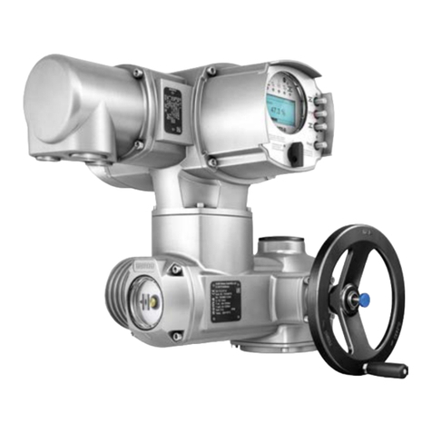
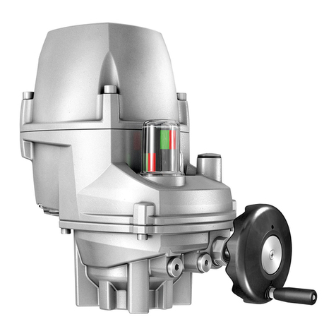
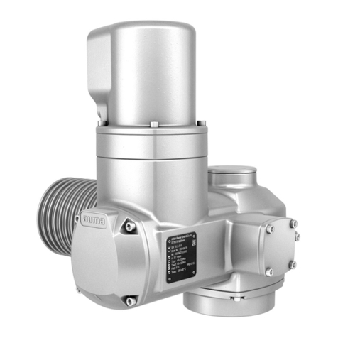
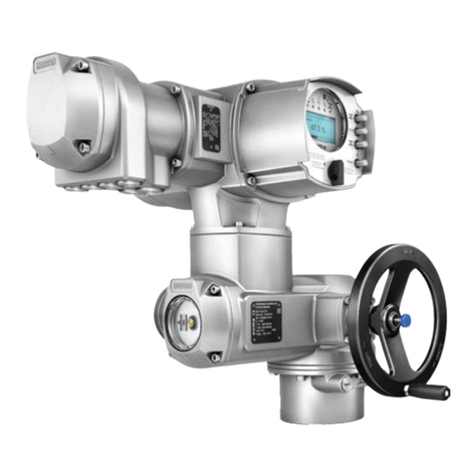
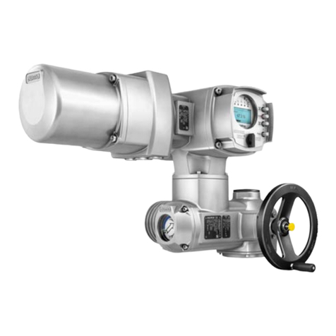
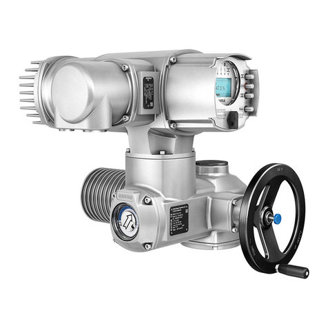
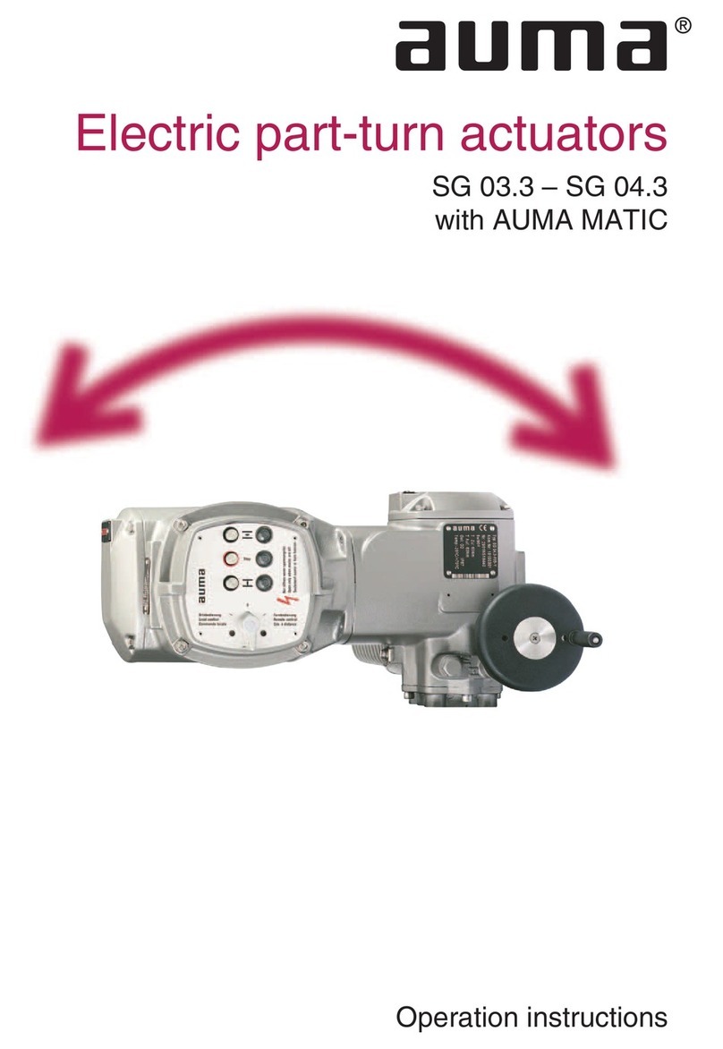
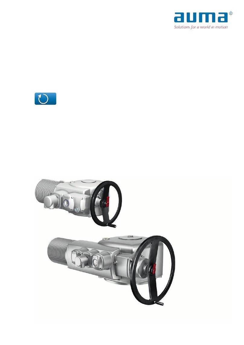
AUMA SV 05.1 User manual

Valve actuators
SV 05.1 – SV 07. 1
Controls MEC 02.1
Marine version
Operation instructions

AUMA valve actuators SV 05.1 – SV 07.1 Operation instructions
Scope of these instructions: These instructions are valid for valve actuators SV 05.1 – SV 07.1 with
controls AUMA MEC 02.1 in marine version.
Table of contents
1. Safety instructions ....................................................................................................................................... 3
1.1. Range of application .................................................................................................................................... 3
1.2. Short description .......................................................................................................................................... 3
1.3. Commissioning (electrical connection) ........................................................................................................ 3
1.4. Maintenance................................................................................................................................................. 3
1.5. Warnings and notes ..................................................................................................................................... 3
1.6. Further notes................................................................................................................................................ 3
2. Technical data............................................................................................................................................... 4
2.1. Valve actuators SV 05.1 – SV 07.1.............................................................................................................. 4
2.2. Controls MEC 02.1....................................................................................................................................... 5
3. Transport and storage.................................................................................................................................. 5
4. Mounting to valve/gearbox .......................................................................................................................... 6
5. Manual operation .......................................................................................................................................... 6
6. Electrical connection.................................................................................................................................... 7
7. Setting of the internal end position detection ........................................................................................... 9
7.1. Setting .......................................................................................................................................................... 9
7.2. Setting for CLOSED ..................................................................................................................................... 9
7.3. Setting for OPEN........................................................................................................................................ 10
7.4. Changing the swing angle.......................................................................................................................... 10
8. Setting of the mechanical position indicator........................................................................................... 10
9. Test run........................................................................................................................................................ 11
10. Controls MEC 02.1 ...................................................................................................................................... 11
10.1. Motor controls......................................................................................................................................... 11
10.2. Control logic............................................................................................................................................ 11
11. Setting of the operating time..................................................................................................................... 11
12. Setting of the position feedback 4 – 20 mA (option)............................................................................... 12
13. Fuses............................................................................................................................................................ 12
14. Maintenance ................................................................................................................................................ 13
15. Wiring diagram............................................................................................................................................ 14
2

Operation instructions AUMA valve actuators SV 05.1 – SV 07.1
1. Safety instructions
1.1. Range of application
AUMA valve actuators are designed for the operation of valves in ships. For other
applications, please consult us. AUMA is not liable for any possible damages
resulting from use in other than the designated applications. Such risk lies entirely
with the user. Observance of these operation instructions is considered as part of
the actuator's designated use.
1.2. Short description
AUMA valve actuators type SV 05.1 – SV 07.1 have a modular design. Motor and
gearing are mounted in a common housing and make up a coaxial unit together with
the output drive shaft.
Manual operation is possible without change-over.
The valve actuators are driven by an electric motor and controlled by the separate
controls MEC 02.1.
In end position OPEN, the limitation of travel is realised via end position sensors.
In end position CLOSED the actuator is swiched off via torque seating (excess
current measuring) or via end position sensors.
1.3. Commissioning (electrical connection)
During electrical operation certain parts inevitably carry lethal voltages. Work on the
electrical system or equipment must only be carried out by a skilled electrician
himself or by specially instructed personnel under the control and supervision of
such an electrician and in accordance with the applicable electrical engineering
rules.
1.4. Maintenance
The maintenance instructions (refer to page 13) must be observed, otherwise a safe
operation of the actuator is no longer guaranteed.
1.5. Warnings and notes
Non-observance of the warnings and notes may lead to serious injuries or damages.
Qualified personnel must be thoroughly familiar with all warnings and notes in these
operation instructions. Correct transport, proper storage, mounting and installation,
as well as careful commissioning are essential to ensure a trouble-free and safe
operation. The following refererences draw special attention to safety-relevant
procedures in these operation instructions. Each is marked by the appropriate
pictograph.
This pictograph means: Note!
”Note” marks activities or procedures which have major influence on the correct
operation. Non-observance of these notes may lead to consequential damage.
This pictograph means: Warning!
”Warning” marks activities or procedures which, if not carried out correctly, can
affect the safety of persons or material.
1.6. Further notes
This pictograph means: Procedure may already be performed by valve
manufacturer !
MOV
M
If actuators are delivered mounted to a valve, this step has been done in the valve
manufacturer's plant.
Setting must be checked during commissioning!
3

AUMA valve actuators SV 05.1 – SV 07.1 Operation instructions
2. Technical data
2.1. Valve actuators SV 05.1 – SV 07.1
Type SV 05.1 SV 07.1
Torque (both directions) max. Nm 25 50
Valve mounting flange according to ISO 5211 Standard F07 F07
Valve shaft ∅max. mm 20 25.4
Square acc. to DIN 79 max. mm 17 22
Operating element (manual operation) Size mm 125 125
Factor 1) 3
Current values for single-phase connection 2) (effective values)
110 – 120 V; 50/60 Hz max. A 3.0 4.8
Consumption at shortest operating time and
max. torque
W 160 260
Weight appr. kg 9 14
Speed 0.25 – 2.5 0.25 – 1.9
Enclosure protection according to EN 60 529 Standard: IP 67
Option: IP 68 3)
Ambient temperature −25 C to +70 °C
Electrical connections for flexible wires: Controls Plug/socket connector with crimp connection, 17-pole, max. 1,5 mm² 4)
Motor Plug/socket connector with crimp connection, 5-pole, max. 1,5 mm² 4)
Insulation class F
Type of duty according to VDE 0530 / IEC 34 Short-time duty S2 – 15 min (OPEN-CLOSE-Duty)
For the electrical operation of each valve actuator the controls MEC 02.1 are necessary.
Screened cables must be used between controls and actuator.
The max. cable length must not exceed 50 m.
1) Conversion factor = output torque / input torque of operating element
2) Maximum values at shortest operating time. Currents are effective values.
3) IP 68 means: Protection against submersion up to max. 6 m head of water for the duration of 72 hours, up to 10 operations during
the submersion.
4) Plug/socket connectors of the Cannon make are delivered with connection possibility for screen braiding. Plug tops and connecting cables
are not part of the AUMA scope of supply. Maximum cable diameters: Controls 18,7 mm; motor 13,5 mm..
4

Operation instructions AUMA valve actuators SV 05.1 – SV 07.1
2.2. Controls MEC 02.1
Type MEC 02.1
Voltage, frequency 110 – 120 V, 50/60 Hz
Internal control voltage 12/24 V DC
Control signals: galvanically isolated
via opto-isolator
(connected externally,
current input 10 – 15 mA)
24 V DC continuous signal
commands OPEN, CLOSE
Option: 24 V DC, self-retaining
commands: OPEN, STOP, CLOSE
Signals (option) Potential free end position signal via change-over contact (24 V, max. 2 A)
Position selector switch REMOTE – OFF
Feedback signal 4 – 20 mA
Control logic CMOS technology
Motor controls 3-phase link with protective network, galvanically isolated via drive stage,
operated by motor controller
Speed control Actual value monitoring by hall sensors. PI speed control with defined load/speed range.
Enclosure protection
according to EN 60 529
Standard: IP 67
Option: IP 68
−25 C to +70 °C
Electrical connection Plug/socket connector see Technical data valve actuators
Weight of controls 1.8 kg
Degree of radio interference
suppression
N, VDE 0815 part 1; A2; 11/90 according to VFG 242
3. Transport and storage
Transport to place of installation in sturdy packing.
Do not attach ropes or hooks to the handwheel for the purpose of lifting by hoist.
If valve actuator is mounted on valve, attach ropes or hooks for the purpose of
lifting by hoist to valve and not to part-turn actuator.
Store in well-ventilated, dry room.
Protect against floor dampness by storage on a shelf or on a wooden pallet.
Cover to protect against dust and dirt.
5

AUMA valve actuators SV 05.1 – SV 07.1 Operation instructions
4. Mounting to valve/gearbox
The easiest position for mounting is when the valve shaft points upright. But
mounting can be done in any other position as well. The valve actuator is delivered
ex works in position CLOSED.
MOV
M
For butterfly valves the mounting position is end position CLOSED.
Thoroughly degrease mounting faces of valve actuator and valve / gearbox.
Put coupling sleeve on valve shaft and secure it (FIGURE A). Ensure that
dimensions X and Y are observed.
A
X
B
Z
Y
Figure A: Valve shaft – coupling
SV 05.1 SV 07.1 Torques
X max. mm 3 3 Recommended
strength class
A2-80
(screw depth: 1,5 x thread ∅)
Y max. mm 6 6 Thread M 6 M 8 M 10 M 12
Z max. mm 35 35 Fastening torques Nm 10 25 50 85
Apply non-acidic grease at toothing of coupling.
Fit actuator so that fixing holes in actuator and valve mounting flange align. If
necessary, move actuator upward one tooth on the coupling. If required, turn
handwheel/crank a little in direction OPEN or CLOSE until holes align.
Ensure that spigot mates uniformly in the recess and that the mounting faces
are in complete contact.
Fasten actuator with bolts. Fasten bolts crosswise with torque wrench (fastening
torques see table).
5. Manual operation
Manual operation is activated by turning the
handwheel/crank. A change-over is not possible.
The handwheel/crank does not rotate during
motor operation.
Turning the handhweel/crank during motor operation results in an
extension or reduction of the operating time, depending on the
direction of rotation.
6

Operation instructions AUMA valve actuators SV 05.1 – SV 07.1
6. Electrical connection
Work on the electrical system or equipment must only be carried out
by a skilled electrician himself or by specially instructed personnel
under the control and supervision of such an electrician and in
accordance with the applicable electrical engineering rules.
AUMA valve actuators SV 05.1 – SV 07.1 are operated via the controls MEC 02.1.
These are designed to be mounted to a separate wall bracket.
Suitable flexible and screened cables must be used between controls and actuator.
The max. permissible cable length between actuator and controls is 50 m.
Controls Actuator
Pins
Pins
Pins
XA1
XG4
XG3
XG2
XG1 Supply
(mains)
XA2
Sockets
Sockets
Sockets
16
3
16
4
Controls
Signals
Actuator
Controls
Actuator
Outp.
Outp.
Inp.
Inp.
Figure B1: Electrical connection
The mains connection and the connection between actuator and controls MEC 02.1
is made by two plug/socket connectors each, with crimp technology.
For crimping a suitable tool, e.g. the Cannon four indent crimp tool, must be used.
Cross sectional areas: Mains/motor: max. 1.5 mm²
Control cables: max. 1.5 mm²
Figure B2: Connection controls (socket carrier) Figure B3: Connection mains/motor (socket carrier)
Plug/socket connector XG2; XA2 Plug/socket connector XG1; XA1
17 contacts (pole diagram figure B2) 5 contacts (pole diagram see figure B3)
Plug/ socket connector XG4 Plug/socket connector XG3
17 contacts (pole diagram figure B2 mirror image) 5 contacts (pole diagram see figure B3 mirror image)
7

AUMA valve actuators SV 05.1 – SV 07.1 Operation instructions
Controls
Run command OPEN 24 V DC
Run command CLOSE 24 V DC
End position signal OPEN (WÖL)
)End position signal CLOSED (WSR
Common potential (0 V)
Common potential (max. 24V 2A)
PE
Actuator
XG1
L1
N
XG2 XG4 XA2
XG3 XA1
PE
End position signal OPEN
End position signal CLOSED
Fault
Fault
Electron. position transmitter 4-20 mA
Electron. position transmitter 4-20 mA
Figure D: Connection diagram MEC 02.1
Check if type of current, supply voltage and frequency correspond to motor data
(refer to name plate at controls MEC).
Remove dust cover (036, 062) (figure C).
036
062
Figure C: Dust cover
Connect plug/socket contacts according to connection diagram (figure D).
Protective earth connection interface is provided and marked according to
DIN 40011.
8

Operation instructions AUMA valve actuators SV 05.1 – SV 07.1
7. Setting of the internal end position detection
For the setting of the end position detection the actuator must be mounted to the
valve.
7.1. Setting
Switch
com
p
artment
LED green
OPEN
LED
yellow
CLOSED
4.2
4.8
4.06
29
Figure F1: Valve actuator SV Figure B2: Switch compartment
7.2. Setting for CLOSED
Turn handwheel/crank firmly into end position CLOSED until valve is closed
(valve is closed when handhweel/crank meets with more resistance when
turning, i.e. when saucer springs in valve cone are sufficiently stretched).
Take off cover at switch compartment (Figure F1)
Switch on power supply.
Loosen both screws (4.06) (Figure F2).
Rotate control disc (4.2) clockwise, until yellow LED lights up brightly to indicate
switching point CLOSED (when inoperative, the LED is already dimly lit).
Afterwards rotate control disc (4.2) minimally (approx. 1 mm) in clockwise
direction.
Hold control disc in position and tighten screws (4.06).
Move valve manually to intermediate position.
Check setting by approaching the switching point in direction CLOSE anew.
9

AUMA valve actuators SV 05.1 – SV 07.1 Operation instructions
7.3. Setting for OPEN
Move valve with handwheel/crank up to the mechanical end stop OPEN (set in
the factory). LED green (OPEN) illuminates.
If switching point is not reached, i.e. LED green is not illuminated, correct setting
value on dial (4.02) as described in subclause 8.4.
Check setting by approaching the switching point in direction OPEN anew.
7.4. Changing the swing angle
Loosen screw (4.8) and pull off control disc (4.2) (Figure F2).
Loosen screw (4.01) at lower side of control disc (Figure G).
Set control disc (4.02) to required value by turning.
Setting must be 3 - 4° less than the swing angle.
Fasten screw (4.01).
Fit control disc (4.2) and secure with screw (4.8).
Check setting by approaching the switching point in direction OPEN anew.
Lower side
Control disc
4.01
Side view
Control disc
4.2
4.2
4.02
Figure G: Setting of the swing angle
8. Setting of the mechanical position indicator
The mechanical position indicator is realised with the white clamping pointer (4.4;
Figure H) below the sight glass (of the switch compartment cover). The clamping
pointer (4.4) shows only the position CLOSED or OPEN with respect to the pipeline.
With the sight glass removed the symbols on the board show the electrically set end
position points.
Move valve actuator manually to end position CLOSED.
Lift clamping pointer (4.4) at indentation slightly and turn it so that it points
crosswise to the pipeline.
When changing the mounting position of the actuator, the
mechanical position indication may have to be re-set!
4.4
Switch compartment 4.4
CLOSED OPEN
Figure H: mechanical position indicator
10

Operation instructions AUMA valve actuators SV 05.1 – SV 07.1
9. Test run
Approach end position CLOSED and end position OPEN electrically and check
seating.
Clean sealing faces at cover and housing; check if O-ring is in good condition.
Apply a thin film of non-acidic grease to the sealing faces.
Replace cover and fasten hex. bolts evenly crosswise.
10. Controls MEC 02.1
10.1. Motor controls
The motor controls are necessary for the operation as well as the speed control of
the special motor. The operating time of the actuator can be set with a potentiometer
(see clause 11) in the electronic controls.
10.2. Control logic
The control logic with interface is required for the actuator controls. It processes the
incoming remote commands OPEN or CLOSE and signals the present end position
of the actuator after detection via relay with change-over contacts.
The indication of faults as e.g. excess torque is given via an output relay.
The run commands (OPEN/CLOSE) must be realised as control signal +24 V. After
cancellation of the run command the actuator stops. After having reached an end
position, the actuator is switched off via end position switches or via torque seating
(excess current measuring).
If a torque excess (Mdmax) occurs during a run in one of the directions, an alarm
circuit switches off the actuator. A further movement in this direction is not permitted.
A run command in the opposite direction or the reaching of an end positon in the
opposite direction (manually) releases the operation lock and makes further
operation possible.
11. Setting of the operating time
The operating time can be adjusted in the controls MEC 02.1 via the potentiometer
R81.
Setting of the
operating time
Potentiometer R81
Figure J: Controls MEC 02.1
11

AUMA valve actuators SV 05.1 – SV 07.1 Operation instructions
12. Setting of the position feedback 4 – 20 mA (option)
R
max
R
min
R11
Figure K1: Valve actuator SV Figure K2: Switch compartment
Take off cover at switch compartment (Figure K1)
Run valve actuator to end position CLOSED.
Turn potentiometer R11 (Figure K2) counter-clockwise until the mechanical stop
is reached. Afterwards turn approx. 2° in clockwise direction.
Set Rmin to 4 mA with setting potentiometer. For 2-wire systems the minimum
current is always 4 mA (see wiring diagram).
Run valve actuator to end position OPEN.
Set Rmax to 20 mA with setting potentiometer.
Check setting by running valve to end positions again.
Replace cover and fasten 4 bolts evenly crosswise.
13. Fuses
F1
F3
F2
Figure L: Fuses, controls MEC 02.1
F1 Mains fuse 6,3 A T; 250 V; IEC 127-2 / V
F2 Primary transformer 0,5 A T; 250 V; IEC 127-2 / III
F3 Secondary transformer 0,5 A T; 250 V; IEC 127-2 / III
12

Operation instructions AUMA valve actuators SV 05.1 – SV 07.1
14. Maintenance
AUMA valve actuators require very little maintenance.
Precondition for reliable service is correct commissioning.
Seals made of elastomers are subject to aging and must therefore regularly be
checked and, if necessary, exchanged.
It is also very important that the O-rings at the covers are placed correctly and the
plug/socket connectors fastened firmly to prevent ingress of dirt or water.
We recommend:
If operated seldom, perform a test run every 6 months. This ensures that the
actuator is always ready to operate.
Check the bolts between the valve and valve actuator for tightness
approximately six months after commissioning and every year thereafter.
If required, re-tighten applying the torques given in the table on page 6.
The gear housing is filled with lubricant in the factory.
13

AUMA valve actuators SV 05.1 – SV 07.1 Operation instructions
15. Wiring diagram
14

Operation instructions AUMA valve actuators SV 05.1 – SV 07.1
Legend for wiring diagram
A1 Interface/control board
A2 Power supply/EMC filter board
A3 Thyristor board
A4 Rotor position monitoring board
A5 Limit seating board
A6 Electronic position transmitter
A7 Selector switch
XG1 Customer connection mains supply
XG2 Customer connection interface
XG3 Connection for the actuator power supply
XG4 Connection for the actuator control signals
XA1 Connection for the actuator power supply
XA2 Connection for the actuator control signals
15

Y003.694/003/en/1.04
Other manuals for SV 05.1
1
This manual suits for next models
1
Table of contents
Other AUMA Controllers manuals
AUMA
AUMA SQEx 05.2 User manual
AUMA
AUMA SVM Series User manual
AUMA
AUMA AMB 01.1 User manual
AUMA
AUMA AC 01.2-22X User manual
AUMA
AUMA SAExC 07.1 User manual
AUMA
AUMA AM 01.1 User manual
AUMA
AUMA ACVExC 01.2 Series Manual

AUMA
AUMA SQ 05.2-SQ 14.2 User manual

AUMA
AUMA SAN 07.1 User manual
AUMA
AUMA SEVEN 2SA7 Instruction manual
