manuals.online logo
Brands
  1. Home
  2. •
  3. Brands
  4. •
  5. TREND
  6. •
  7. Controllers
  8. •
  9. TREND LonMark IQL13+ Series User manual

TREND LonMark IQL13+ Series User manual

Other TREND Controllers manuals

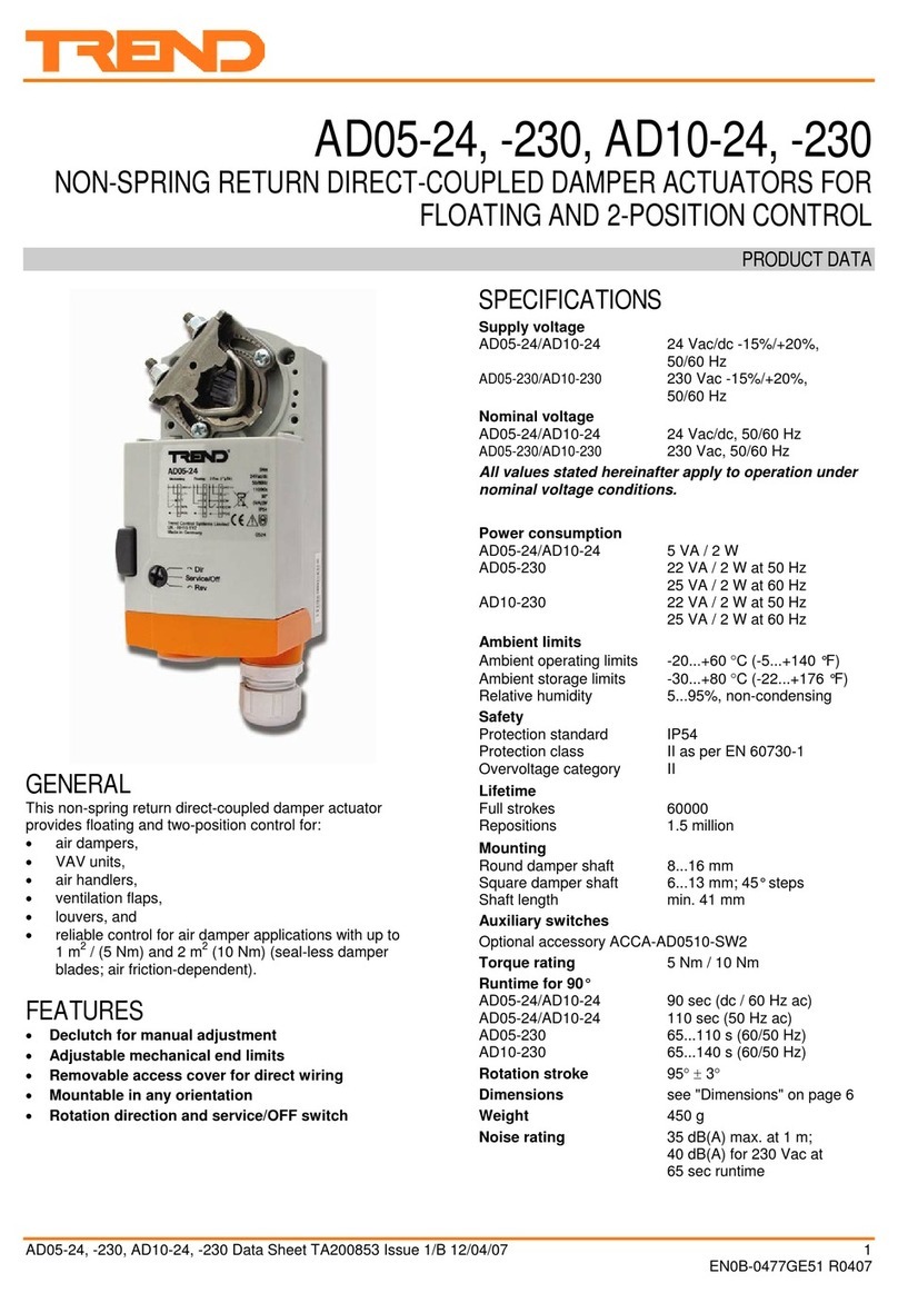
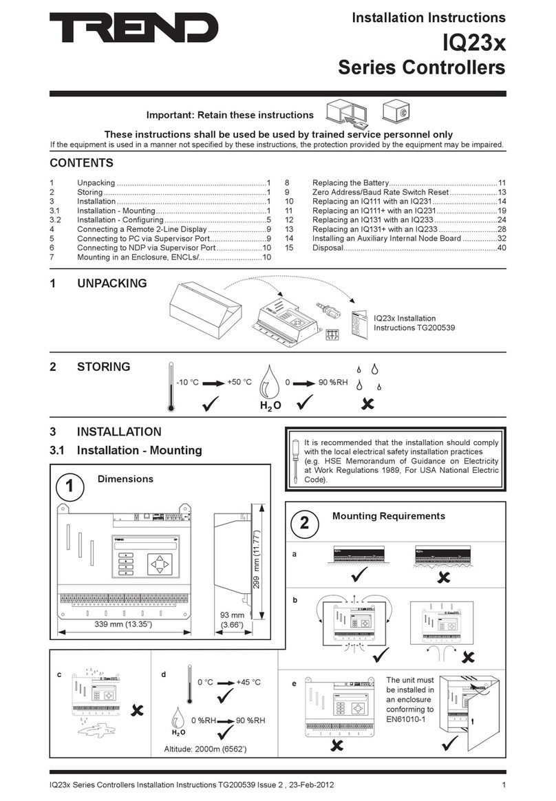
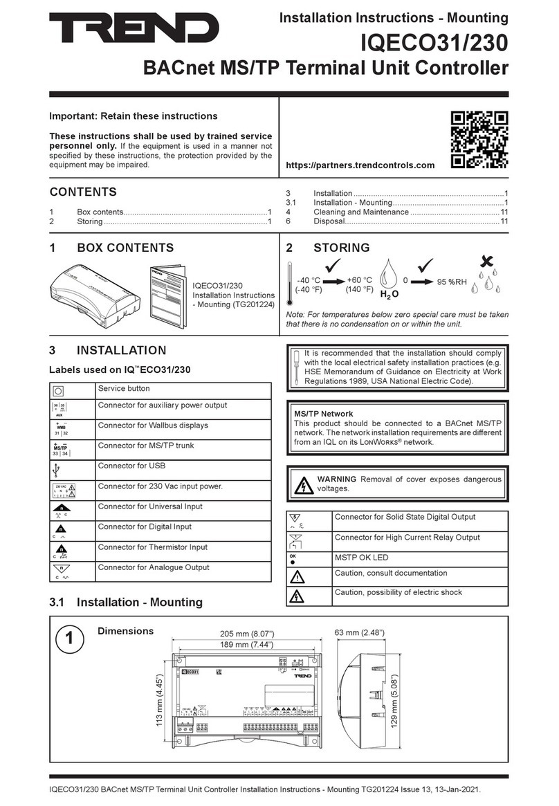
TREND IQECO31/230 User manual

TREND

TREND IQECO31/230 User manual

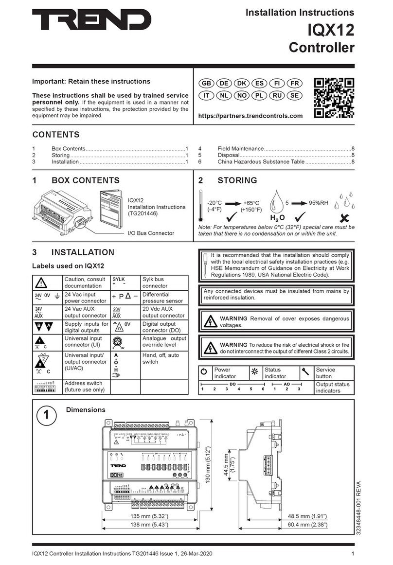
TREND IQX12 User manual

TREND

TREND IQX12 User manual

TREND CNC2 User manual

TREND

TREND CNC2 User manual

TREND INC2 User manual

TREND

TREND INC2 User manual

TREND IQ41 Series User manual

TREND

TREND IQ41 Series User manual

TREND IQ422 User manual

TREND

TREND IQ422 User manual

TREND CNC2 User manual

TREND

TREND CNC2 User manual

TREND IQ3xcite User manual

TREND

TREND IQ3xcite User manual

TREND IQ3 series User manual

TREND

TREND IQ3 series User manual

TREND IQ251 User manual

TREND

TREND IQ251 User manual

TREND AL0620-24-K User manual

TREND

TREND AL0620-24-K User manual

TREND AD05-24 Operation manual

TREND

TREND AD05-24 Operation manual

TREND IQ41 Series User manual

TREND

TREND IQ41 Series User manual

TREND IQ23 Series User manual

TREND

TREND IQ23 Series User manual

TREND NBOX(B)/CNC2 User manual

TREND

TREND NBOX(B)/CNC2 User manual

TREND ADS10 Series User manual

TREND

TREND ADS10 Series User manual

TREND IQ422 User manual

TREND

TREND IQ422 User manual

TREND IQ4E User manual

TREND

TREND IQ4E User manual

Popular Controllers manuals by other brands

Sunricher SR-ZV9003T3-RGBW-US Installation

Sunricher

Sunricher SR-ZV9003T3-RGBW-US Installation

Ksenia intro Installation and configuration manual

Ksenia

Ksenia intro Installation and configuration manual

Inovance CAN200 Series manual

Inovance

Inovance CAN200 Series manual

Gauzy LC6 FLEX Controller Installation and operation guide

Gauzy

Gauzy LC6 FLEX Controller Installation and operation guide

Viking SLP-1 Technical practice

Viking

Viking SLP-1 Technical practice

CKD KBX-30E-U Series instruction manual

CKD

CKD KBX-30E-U Series instruction manual

Sharp Energy Sun Flux User manual & installation guide

Sharp Energy

Sharp Energy Sun Flux User manual & installation guide

Yamaha RCX40 user manual

Yamaha

Yamaha RCX40 user manual

AB Quality PowerFlex 400 Frames D-H Service bulletin

AB Quality

AB Quality PowerFlex 400 Frames D-H Service bulletin

Yamaha MJC8 owner's manual

Yamaha

Yamaha MJC8 owner's manual

AL-KO ATC operating instructions

AL-KO

AL-KO ATC operating instructions

Savant SmartControl 2 Deployment guide

Savant

Savant SmartControl 2 Deployment guide

GameSir T3S user manual

GameSir

GameSir T3S user manual

Kostal inveor operating manual

Kostal

Kostal inveor operating manual

Emerson Yarway 20-55 Operating and safety instructions

Emerson

Emerson Yarway 20-55 Operating and safety instructions

CoCo ACM-LV24 Quick installation guide

CoCo

CoCo ACM-LV24 Quick installation guide

Brooks SLA5810/20 Installation and operation manual

Brooks

Brooks SLA5810/20 Installation and operation manual

SIGMA TEK SR 011 Technical manual

SIGMA TEK

SIGMA TEK SR 011 Technical manual

manuals.online logo
manuals.online logoBrands
  • About & Mission
  • Contact us
  • Privacy Policy
  • Terms and Conditions

Copyright 2025 Manuals.Online. All Rights Reserved.

IQL13+/xxx Installation Instructions TG200383 Issue 3/B 19/08/04 1 - 1
1
Installation Instructions - Sheet 1
IQL13+/xxx
LonMark Terminal Unit Controllers
Important: Retain these instructions
1
32
1.3 Installation - Fixing
CONTENTS
1.1 Unpacking 1-1
1.2 Storage 1-1
SHEET 1: Installation Instructions - Sheet 1
1.1 Unpacking
Sheet2:Fixing/Configuration
Sheet 1: Fixing
IQL13+/xxx
InstallationInstructions
TG200383
H O
2
+50 °C
(122 °F) 0
-10 °C
(14 °F) 90 %RH
It is recommended that the
installation should comply with
the HSE Memorandum of
GuidanceonElectricityatWork
Regulations1989.
1 3 +
L
L A N
N I D
S t r a t e g y
: : : : :
O / S
S e r i a l N o
2 3 0 V a c
~
2 4 V C O M
2 1 2 2 2 3 2 4 2 5 2 6 2 7 2 81 2 3
C O M
1 2 3 54 6 7
4 5 6 7 8 9 1 0 1 1 1 2 1 3 1 4 1 5 1 6 1 7 1 8 1 9 2 0
12 3 4 5
~
2 4 V
L O N
2 9 3 0 3 1 3 2
L O N
O K
S R V
P I N
C
2 4 V a c
129 mm (5.08”)
75 mm (3”)
205 mm (8.07”)
Dimensions
63 mm (2.48”)
1
1.3 Installation - Fixing 1-1
2.1 Installation - Fixing (continued) 2-1
2.2 Installation - Configuration 2-2
3. Installation - Configuration (continued) 3-1
1 3 +
L
L A N
N I D
S t ra t e g y
: : : : :
O / S
S e r i a l N o
2 3 0 V a c
~
24 V C O M
2 1 2 2 2 3 2 4 2 5 2 6 2 7 2 81 2 3
C O M
1 2 3 54 6 7
4 5 6 7 8 9 1 0 1 1 1 2 1 3 1 4 1 5 1 6 1 7 1 8 1 9 2 0
12 3 4 5
~
24 V
L O N
2 9 3 0 3 1 3 2
L O N
O K
S R V
P I N
C
2 4 V a c
b
a
Requirements
2
Note that this product may involve Lonworks system
integration as referred to in section 2.2 step 4: this
procedure should only be performed by an installer
with LonWorks engineering expertise.
!
Sheet 3: Configuration
1.2 Storage
IQL13+/xxx Installation Instructions - Sheet 1
IQL13+/xxx Installation Instructions TG200383 Issue 3/B 19/08/04
1 - 2
1.3 Installation - Fixing (continued)
4 holes
1 3 +
L
L A N
N I D
S t r a t e g y
: : : : :
O / S
S e r i a l N o
2 3 0 V a c
~
2 4 V C O M
2 1 2 2 2 3 2 4 2 5 2 6 2 7 2 81 2 3
C O M
1 2 3 54 6 7
4 5 6 7 8 9 1 0 1 1 1 2 1 3 1 4 1 5 1 6 1 7 1 8 1 9 2 0
12 3 4 5
~
2 4 V
L O N
2 9 3 0 3 1 3 2
L O N
O K
S R V
P I N
C
2 4 V a c
∅6 mm
(0.24”)
Mounting
1 3 +
L
LA N
N I D
S tr a te g y
: : : : :
O / S
S er ia l N o
23 0 V a c
~
24V CO M
21 22 2 3 2 4 2 5 2 6 2 7 2 81 2 3
CO M
1 2 3 54 6 7
4 5 6 7 8 9 1 0 1 1 12 1 3 1 4 15 1 6 17 1 8 1 9 2 0
12 3 4 5
~
24V
L O N
29 3 0 31 3 2
LO N
OK
SR V
PI N
C
24 V ac
c
1 3 +
L
LA N
N I D
S t r a t e g y
: : : : :
O / S
S er ia l N o
2 30 V a c
~
24 V CO M
21 2 2 2 3 2 4 2 5 2 6 27 2 81 2 3
CO M
1 2 3 54 6 7
4 5 6 7 8 9 1 0 1 1 12 1 3 14 1 5 1 6 1 7 1 8 1 9 2 0
12 3 4 5
~
24 V
L O N
29 3 0 3 1 32
LO N
OK
SR V
PI N
C
24 V ac
114 mm
(4.49”)
3
Lift Hinged Cover
4
189 mm (7.44”)
a
bc
d
H O
2
+45 °C
(113 °F)
0
0 °C
(32 °F)
90 %RH
1 3 +
L
LA N
N I D
S tr a te g y
: : : : :
O / S
S er ia l N o
23 0 V ac
~
24 V CO M
21 22 2 3 2 4 2 5 2 6 27 2 81 2 3
CO M
1 2 3 54 6 7
4 5 6 7 8 9 1 0 1 1 1 2 13 1 4 15 1 6 1 7 18 19 20
12 3 4 5
~
24 V
L O N
29 3 0 31 3 2
LO N
OK
SR V
PI N
C
24 V ac
1 3 +
L
L A N
N I D
S t r a te g y
: : : : :
O / S
S e r i a l N o
2 3 0 V a c
~
24V C O M
2 1 2 2 2 3 2 4 2 5 2 6 2 7 2 81 2 3
C O M
1 2 3 54 6 7
4 5 6 7 8 9 1 0 1 1 1 2 1 3 1 4 1 5 1 6 1 7 1 8 1 9 2 0
12 3 4 5
~
2 4 V
L O N
2 9 3 0 3 1 3 2
L O N
O K
S R V
P I N
C
2 4 V a c
Ifnotinstalledwelloutsidenormal
reach (e.g behind false ceiling)
e
Protection: IP20, NEMA 1
Requirements (continued)
2
f
Avoidlocationswherecorrosive
fumesorexplosivevapoursare
present. Avoid electrical noise
interference
either surface mount
or DIN rail mount
1 3 +
L
L A N
N I D
S t r a t e g y
: : : : :
O / S
S e r i a l N o
2 3 0 V a c
~
24V C O M
2 1 2 2 2 3 2 4 2 5 2 6 2 7 2 81 2 3
C O M
1 2 3 54 6 7
4 5 6 7 8 9 1 0 1 1 1 2 1 3 1 4 1 5 1 6 1 7 1 8 1 9 2 0
12 3 4 5
~
2 4 V
L O N
2 9 3 0 3 1 3 2
L O N
O K
S R V
P I N
C
2 4 V a c
1 3 +
L
L A N
N I D
S t ra t e g y
: : : : :
O / S
S e r i a l N o
2 3 0 V a c
~
24V C O M
2 1 2 2 2 3 2 4 2 5 2 6 2 7 2 81 2 3
C O M
1 2 3 54 6 7
4 5 6 7 8 9 1 0 1 1 1 2 1 3 1 4 1 5 1 6 1 7 1 8 1 9 2 0
12 3 4 5
~
24V
L O N
2 9 3 0 3 1 3 2
L O N
O K
S R V
P I N
C
2 4 V a c
ab c d
WARNING: Failure to use a screwdriver
to open the cover will cause damage to
the unit.
IQL13+/xxx Installation Instructions TG200383 Issue 3/B 19/08/04 1 - 3
Installation Instructions - Sheet 1 IQL13+/xxx
L o n AS C N L o n B L o n AS C N L o n B
L I N C
L O N T E R M I N A T O R
1A
1
L O N R O U T E R
234
B
1234
I Q L
y
A
1
L O N R O U T E R
234
B
1234
L O N T E R M I N A T O R
1
L O N T E R M I N A T O R
1
z
w
I Q L
y z
w
I Q L
y z
w
I Q L
y z
w
Connect Power
5
DO NOT APPLY
POWER
O
I
1 3 +
L
L A N
N I D
S t r a t e g y
: : : : :
O / S
LNE
2 3 0 V a c
1 2 3
Cleanearthsconsistingof
short (<300 mm, 12”)
stranded copper wire
(>=1.5 mm2, 16 AWG) to
a substantial earthed
metal part (e.g. cable
tray) are recommended
Terminal size 0.5 to 2.5 mm2
(14 to 20 AWG)
1.3 Installation - Fixing (continued)
1 3 +
L
L A N
N I D
S t r a t e g y
: : : : :
O / S
6
T e r m i n a t o r
T e r m i n a t o r
T e r m i n a t o r
Lon - FTT (free topology)
Startopology Bus topology Looptopology
*Terminate Lon bus at one end only
polarity
independent
Connect Lon
Lon
Lon
L O N
2 9 3 0 3 1 3 2
**
*
Do not allow wires to cross on a loop
continued over page
2 4 V a c
1 2 3
24Vac
WARNING: This apparatus
must be earthed (via earth
terminal).
Earth 24 Vac supply neutral
at transformer
/24VACoption /230 option
IQLconsumption
<= 12.1 VA (2.5 VA +
power to triac outputs)
IQLconsumption
<= 13 VA (3 VA + power
to triac outputs)
100 mF, 50 V min
100
m
F, 50 V min
Terminator
e.g.
LONTERMINATOR Maximum 64 nodes per Lon
segment
Maximum 40 IQLs (and
LONCs) per virtual Lan
Recommend terminate at LINC
or Router
IQL13+/xxx Installation Instructions - Sheet 1
IQL13+/xxx Installation Instructions TG200383 Issue 3/B 19/08/04
1 - 4
T
ST/ET
9888
/
8
K/ST/ET
998 8
/
8
EK/ST/ET
9998
/
8
FEK/ST/ET
9999
/
8
K/LQI/DR
9
S
9
/
8
/
8
SOK/LQI/DR
9
S
998
/
8
FSOK/LQI/DR
9
S
999
S
/
8
Pushbutton
or PIR input
Window o
r
Alarm
contact
Local
Space
Temperature
Sensor
Local Setpoint
Adjust
Potentiometer
Fan S
p
eed Select
Auto
Off
C O M
2 1 2 2 2 3 2 4 2 5 2 6 2 7 2 8
C O M
12 3 4 5
C
Connect Inputs and Outputs
7If non standard strategy, follow
special installation instructions and
jump to section 2.1 step 14
Connect Inputs
8
1 3 +
L
L A N
N I D
S t r a t e g y
: : : : :
O / S
Non-standardStrategy
InstallationInstructions
IQL13+/xxxInstallation
Instructions, TG200383 -
Sheet 2
Configure/Commission
9
6
1.3 Installation - Fixing (continued)
Connect Lon (continued)
If used with LPT-10 (powered bus), cable lengths differ - see “Link Power Transceiver
User’sGuide (078-0105-01C)”.
LINC LINC
IQ Outstations
LonMark
Device
Lonworks bus
IQL
IQ Outstation
Normal IQ System current loop Lan cable is not
recommended
Do not use screened cable
Terminal size 0.5 to 2.5 mm2 (14 to 20 AWG)
2
1
23654
TB/TS /K /E
/F
C O M
2 1 2 2 2 3 2 4 2 5 2 6 2 7 2 8
C O M
12 3 4 5
C
SensorsTB/TS,TB/TS/K,TB/TS/KE,TB/TS/KEF
recommended; wire as shown below.
RoomDisplayModule(RD-IQL/K,/KOS,/KOSF)
provides monitor and control; wired as shown
below:
RD-IQL
2 6 2 7
4
C
polarity
independent
Note that the IQL must be
correctly set up to use the
RD-IQL,seesection3step 15
∆T
input included in TB or RD
Sseparate input may be used
/Input either cannot be connected, or will be ignored
Connection of separate device to input required
PIR
Terminal size 0.5 to
2.55 mm2 (14 to
20 AWG)
Pushbutton or PIR
inputtypeselectedby
configuration
parameter W6
PIR
Note that terminal types COM and
Cshouldnotbeconnectedtogether
elbaChtgnelsubxaMedonotedonxaM
20158nedleB)sdy545(m005)sdy545(m005
metsysQI
002/FH/61/0/1/PT
)1748nedleB(
)sdy
545(m005)sdy034(m004
GWA22,VIleveLLU)sdy545(m005)sdy034(m004
8.0x2x2Y)tS(YJ)sdy545(m005)sdy053(m023
,5.taCA86
25AIT
GWA42 )sdy094(m054)sdy072(m052
IQL13+/xxx Installation Instructions TG200383 Issue 3/B 19/08/04 2 - 1
2
Installation Instructions - Sheet 2
IQL13+/xxx
LonMark Terminal Unit Controllers
Heat/Cool
Damper
Raise
Lower
Common
not used
~
24V
54 6 7
1 5 1 6 1 7 1 8 1 9 2 0
<
~
24V
<
not used
Raise
Lower
Common
Heat or Cool
Valve
~
24V
54 6 7
1 5 1 6 1 7 1 8 1 9 2 0
<~
24V
<
Raise
Lower
Common
Raise
Lower
Common
Cool Valve
Heat Valve
~
24V
54 6 7
1 5 1 6 1 7 1 8 1 9 2 0
<
~
24V
<
Heat or Cool
Valve
not used
~
24V
54 6 7
1 5 1 6 1 7 1 8 1 9 2 0
<~
24V
<
1 3 +
L
L A N
N I D
S t r a t e g y
: : : : :
O / S
Cool Valve
Heat Valve
~
24V
54 6 7
1 5 1 6 1 7 1 8 1 9 2 0
<
~
24V
<
SHEET 2: Installation Instructions - Sheet 2
Fixing
10
IQL13+/xxxInstallationInstructions,
TG200383 - Sheet 1
11
(24 Vac, 400 mA maximum shared between
24 Vacauxiliaryoutputandalltriacoutputsused)
/AR2 /WR2 /WR4
2.1 Installation - Fixing (continued)
/WT2 /WT4
1
Connect Heat/Cool Outputs
terminal size 0.5 to 2.5 mm2(14 to 20 AWG)
Connect Fan Outputs
12
1 3 +
L
L A N
N I D
S t r a t e g y
: : : : :
O / S
WARNING: The wires may be connected to
hazardousvoltages. Disconnect power
beforeattempting any wiring.
5Amaximum@240 Vac resistive or inductive (cosø>=0.4)
5A@30Vdc(resistive),2A@24Vdc(inductive,T<=30 mS)
Arc suppression
TG200208
terminal size 0.5 to 2.5 mm2(14 to 20 AWG)
OUT1 OUT2 OUT3
Fan
Autotransformer
Fan
1 2 3
6 7 8 9 1 0 1 1 1 2 1 3 1 4
For a fan without speed control wires, an auxiliary
autotransformer can be used to produce control
voltages. Use the following diagram:
An autotransformer with built-in self-resetting
thermal overload protection is recommended.
IQL13+/xxx Installation Instructions - Sheet 2
IQL13+/xxx Installation Instructions TG200383 Issue 3/B 19/08/04
2 - 2
2.2 Installation - Configuration
1 3 +
L
L A N
N I D
S t r a t e g y
: : : : :
O / S
Connect 24 Vac Auxiliary
Output
13
4 5
2 4 V a c
Load
8
Close Hinged Cover
14
2.1 Installation - Fixing (continued)
1 3 +
L
L A N
N I D
S t r a t e g y
: : : : :
O / S
S e r i a l N o
O
I
LINC LINC
IQ Outstations
LonMark
Device
Lonworks bus
IQL
IQ Outstation
(Check Lon, LINCs)
LON OK (green)
Flashes every 24 s, ON after 1½ mins
Switch On
2
Check IQL/LINC on Lon
3
Flashes every 1 s (Deaf IQL. Check Lon)
a
b
terminal size 0.5 to 2.5 mm2
(14 to 20 AWG)
400 mA maximum shared
between 24 Vac Auxiliary
output and all triac outputs
used.
Tear off Label Strip
1
1 3 +
L
L A N
N I D
S t r a t e g y
: : : : :
O / S
S e r i a l N o
2 3 0 V a c
~
24V C O M
2 1 2 2 2 3 2 4 2 5 2 6 2 7 2 81 2 3
C O M
1 2 3 54 6 7
4 5 6 7 8 9 1 0 1 1 1 2 1 3 1 4 1 5 1 6 1 7 1 8 1 9 2 0
12 3 4 5
~
24V
L O N
2 9 3 0 3 1 3 2
L O N
O K
S R V
P I N
C
2 4 V a c
O / S
L A N
N I D
S t r a t e g y
S e r i a l N o
117 027
00:A0:25:36:51:00
IQL1x WR4 E 06
IQL1xWR4_50100025
IQL1xWR4_50100025
N I D
S e r i a l N o
00:A0:25:36:51:00
S e r i a l N o
N I D
S e r i a l N o
0 0 : A 0 : 2 5 : 3 6 : 5 1 : 0 0
S e r i a l N o
I Q L 1 W R 4 _ 5 0 1 0 0 0 2 5
L A N
O / S
‘locate’
IQL13+/xxx Installation Instructions TG200383 Issue 3/B 19/08/04 2 - 3
Installation Instructions - Sheet 2 IQL13+/xxx
1 3 +
L
L A N
N I D
S t r a t e g y
: : : : :
O / S
S e r i a l N o
See LonWorks network management
tool manual. See IQ System LonWorks
Products Engineering Manual
(TE200292). LonWorks System
Integrator must have LonWorks
engineeringexpertise.
a). When installing IQL in LonWorks tool, press
service button when requested.
b). The IQL network image can be obtained from
www.lonmark.org, or from www.pnet.trend-
controls.com.
c). Set up bindings if required (bind network
variablesbetweenIQLandLonMarkdevices).
IQL13+ Data Sheet
TA200205 for Lon
networkvariables(NVs)
Install using LonWorks Network Manager Tool
4If a binding IQLs to LonMark devices
or b LINCs version <3.23 straddle router
or c otherdeviceshaveaddressconflictswithIQSystemdevices
or d LONROUTERs used on installed system
SRV PIN
service button
LINC
Lon
IQL
Lonmark
device
IfoneIQSystemLondeviceisinstalled,allmustbeinstalled.
2.2 Installation - Configuration (continued)
Lon
LCI
IQL
Note that a PIN may be required to make
changes.IfthePINhasbeenforgottenthe
users should contact their supplier
(installers contact Technical Support) quoting the
generatornumberandneuronid(bothfromAddress
module)whereuponadefaultPINwillbesupplied.
Thiswillonlyworkforthreeattemptsatenteringthe
PIN. After the default PIN is entered a new PIN
should be set up and remembered.
Lon
LCI
IQL
Connect software tool for commissioning
5if required
Exercise I/O
6
If IqlTool2 available
IqlTool2 Manual TE200185
Use IqlTool2 to monitor inputs and exercise outputs
IqlTool2Manual
TE200185
LCIInstallation
InstructionsTG200429
SET Manual TE200147
IqlTool2(SET)
IqlTool2runswithinSETV5.1(orlater)
RS232 cable
supplied with LCI
Lon adapter cable
supplied with LCI
IqlTool2
(SET)
Note that IqlTool2 may also be used for mapping the
Lonsegment,resolvingduplicateaddresses on Lon,
water balancing (/WR2, /WR4, /WT2, /WT4 only),
identificationviaservicebutton,associatingwithSDU-
LON (for other uses see later)
IQL13+/xxx Installation Instructions - Sheet 2
IQL13+/xxx Installation Instructions TG200383 Issue 3/B 19/08/04
2 - 4
2.2 Installation - Configuration (continued)
Test input/output functionality
7
Non-standardStrategyInstallationInstructions
If non standard strategy follow special installation instructions and jump to section 3 step 15.
01 0 0
01 0 0
2RA/2RW/4RW/2TW/4TW/
01 0 0
100
0
heat
100
0
cool
OUT4,5
damper
OUT4,5
damper
OUT4,5
If W2=0
(Winter Mode)
heating
OUT4,5
If W2=1
(Summer Mode)
cooling
OUT4,5
heat valve
OUT6,7
cool valve
OUT4
If W2=0
(Winter Mode)
heating
OUT4
If W2=1
(Summer Mode)
cooling
OUT4
heat valve
OUT6
cool valve
100
0
1 3 +
L
L A N
N I D
S t r a t e g y
: : : : :
O / S
S e r i a l N o
S
S
6
Check Strategy, Sensor/Fan/Heat Cool Outputs/Electric Heater
8
IN1
OUT1 heat
100
0
cool
01 0 0
01 0 0
01 0 0
01 0 0
01 0 0
Configuration (continued)
9
IQL13+/xxxInstallation
InstructionsTG200383
Sheet 3
3
IQL13+/xxx Installation Instructions TG200383 Issue 3/B 19/08/04 3 - 1
3
Installation Instructions - Sheet 3
IQL13+/xxx
LonMark Terminal Unit Controllers
SHEET 3: Installation Instructions - Sheet 3
3. Installation - Configuration (continued)
Fixing/
Configuration
10
IQL13+/xxxInstallation
Instructions, TG200383 -
Sheet 2
2
2RA/2RW/4RW/2TW/4TW/
1 3 +
L
L A N
N I D
S t ra t e g y
: : : : :
O / S
S e r i a l N o
Window
fan off
Check Operation - Window Contact Input
11
IN5 OUT1, 2, 3
if Window Mode (W5=1)
01 0 0
100
0
heat
100
0
cool
OUT4,5
damper OUT4,5
valve closes
01 0 0
OUT4,5
heat valve
01 0 0
OUT6,7
cool valve
OUT4 OUT4
1 0 0
0
heat
100
0
cool
damper goes
to neutral
01 0 0
valve closes
01 0 0
heat valve
01 0 0
cool valve
OUT6
1 3 +
L
L A N
N I D
S t r a t e g y
: : : : :
O / S
S e r i a l N o
PIR if in
standby
Pushbutton
if non-occupied
or standby
fan on
Check Operation
-PushbuttonorPIRInput
12
1 3 +
L
L A N
N I D
S t r a t e g y
: : : : :
O / S
S e r i a l N o
LocaladjustmentcanbeprovidedbyTB/TS/K,/KE,
/KEF or RD-IQL/K, /KOS, /KOSF (see section 1.3
step 8).
Wait 6 secs at each end to calibrate potentiometer
Check Operation
- Local SP Adjust
13
If Fan Speed Auto
If Fan Speed Auto
IN4 OUT1, 2, 3 OUT1, 2, 3
IN2
Pb/PIRinputtypeselectedby
configurationparameter W6
- see step 15 .
see table
section 2.2
step 8
Pushbutton can be provided by TB/TS/KE, /KEF, or
RD-IQL/KOS, /KOSF (see section 1.3 step 8)
100
0
heat
1 0 0
0
cool
see table
section 2.2
step 8
IQL13+/xxx Installation Instructions - Sheet 3
IQL13+/xxx Installation Instructions TG200383 Issue 3/B 19/08/04
3 - 2
3. Installation - Configuration (continued)
Set up Strategy Parameters
15 if required Use IqlTool2 (see section 2.2 step 5 ) and text
communications
For standard strategies use table below, else refer to
non-standard strategy installation instructions
If required the strategy type may be changed (e.g. /AR2 to /WR2) : IQL13+/xxx data
sheet TA200284
Notethatany changes to the strategy parameters shouldimmediatelybefollowedby a write to the address
module,[text comms command, R(z=0), recommended],tocommitchanges to flash memory.
* Default depends on strategy
IfusedwithRD-IQL(seesection1.3step8),thefollowingmustbeconfigured:LocalSpaceTempType
S9(Y=6), Local SP Adjust Type S10(Y=6),Local Fan Speed Type S11(Y=6), O=Pb I=PIR W6(S=O)
default,Remote Fan Spd K7(V=4) default, followed by R(z=1) to write changes to flash and reset.
Configuration for RD-IQL is facilitated by IqlTool2.
IfthesensoronIN1istobeused,leavelocalSpaceTemptypeatdefault,S9(Y=1).Ifthefanspeedswitch
on IN3 is to be used, leave Local Fan Speed type at default, S11(Y=3).
Check Operation - Fan Speed Select
14
1 3 +
L
L A N
N I D
S t r a t e g y
: : : : :
O / S
S e r i a l N o
A u t o
O f f
IN3
OUT1, 2, 3
If Occupied and Remote Fan Speed (K7) Auto
Fan Speed Switch can be provided by TB/TS/KEF or
RD-IQL/KOSF (see section 1.3 step 8)
retemaraPlebaLnoitcnuFtluafeD
)V(1KtniopteSetomeRyletomerdetsujdaebnactnioptesesaB C°02
)V(2KpmeTecapSetomeR de
tcennocsidrosneslacolfiro,rosnesnoLotdnuobfidesU C°02
)V(3KdnbdaeDCCOccOgnirudtnioptesdnuoradnabdaeD C°1
)V
(4KdnbdaeDybdnatSybdnatSgnirudtnioptesdnuoradnabdaeD C°2
)V(5KdnbdaeDCCONccoNgnirudtnioptesdnuoradnabdaeD C°
21
)V(6KccOetomeRybdnatS=3,ssapyB=2,ccoN=1,ccO=0etatssteS deipuccO=0
)V(7KdpSnaFetomeRotuA=4,hgiH=3,deM=2,wo
L=1,ffo=0deepssteS otuA=4
)V(8KtesffOPSetomeR detcennocsidsitsujdalacolfirorosneSnoLaotdnuobfidesU C°0
)V(5
1KegnartesffO.toptsujdaPSlacoLfoegnarsenifeD C°2
)S(1WepiP2=IepiP4=O )2TW,2RW(I=1W)2RA,4TW,4RW(O=1Wegnahcyg
etartS*
)S(2WedoMremmuS )2TW/,2RW/rofdesuylno()ylnolooc(remmuSro)ylnotaeh(retniW retniW=O
)S(3WelbasiDcelEIot
tesfiretaeHcirtcelEelbasiD celEelbane=O
)S(4WriA=IretaW=O)RA(I=4W)TW,RW(O=4WegnahcygetartS*
)S(5WedomwodniWOo
ttesfitcatnocmrala,IottesfitcatnocwodniW tcatnocmrala=O
)S(6WRIP=IbP=OOottesfinottubhsuP,IottesfiRIP nottu
bhsup=O
)S(7WnoitidnoCtsorFdeipucconufi)2RA/ton(%89otgnitaehsedirrevO tsorfon=O
)S(8WnwodtuhSetomeRorezotloo
c/taehstesdna,nafffostuhS nwodtuhson=O
)G(1LniaGpooLtaeH 04
)I(1LlargetnIpooLtaeH snim0
)G(2LniaGpooLlooC 04-
)I
(2LlargetnIpooLlooC snim0