manuals.online logo
Brands
  1. Home
  2. •
  3. Brands
  4. •
  5. Elko
  6. •
  7. Controllers
  8. •
  9. Elko iNELS Air AirSLC-100 User manual

Elko iNELS Air AirSLC-100 User manual

1 / 2
AirSLC-100/DALI
02-1/2018 Rev.: 0
7
9
1
8
6
2
1
3
4
5
10
11
L
N
DALI(-)
DALI(+)
L
N
DALI (+)
DALI (-)
DALI
ELKO EP, s.r.o.
Palackého 493
769 01 Holešov, Všetuly
Czech Republic
Tel.: +420 573 514 211
e-mail: [email protected]
www.elkoep.com
Characteristics
Description
EN
Street light controller (DALI)
Made in Czech Republic
Example connection
When power is applied, the module sends a start message.
It monitors the current flow and sends a data message according to the settings in the
application (within 5 min - 24 hrs). In case of a significant change in measurement, it
sends the data message immediately.
Controls lighting based on application command.
• The TEST button is for service purposes.
Long press of the TEST button - adjust the brightness (ascending or descending ramp).
Briefly press the TEST button to turn on / off the connected device.
ballast
brown
light blue
black (V)
red
dark blue
light source
For the management of DALI BUS there is not an exact cable type recommended, but
it is important to keep some installation conditions. For DALI BUS lines up to 100 m
the recommended min. conductor cross section is 0.5 mm2. For management between
100 m -150 m a cross section of 0.75 mm2and more than 150 m the recommended min is
1.5 mm2. Management of more than 300 m is not recommended. The voltage drop at the
end of the installation may not be greater than 2 V.
General instrucions
Cloud app assignment
It is done in your Smartphone application. Enter the relevant information on the product
cover into the application.
Internet of Things (IoT)
• The IOT wireless communications category describes the Low Power Wide Area
(LPWA). This technology is designed to provide full-range coverage both inside and
outside buildings, energy-saving and low-cost operation of individual devices. Indi-
vidual networks - LoRa - are available to use this standard.
LoRa network information
• The network is bidirectional and its communication uses free frequency band.
• 865 - 867 MHz India
• 867 - 869 MHz Europe
• 902 - 928 MHz North America, Japan, Korea
• The advantage of this network is the possibility of freely deploying individual stations
in local locations, thus strengthening their signal. It can therefore be used eciently in
company premises or, for example, in local parts of cities.
• For more information on this technology, please visit www.lora-alliance.org.
Caution for proper operation:
• Products are installed according to the wiring diagram given for each product.
• For proper device functionality, it is necessary to have sucient coverage of the se-
lected network at the installation site.
• At the same time, the device must be registered in the network. Successful device reg-
istration on a given network requires a charge for trac.
• Each network oers dierent tari options - it always depends on the number of mes-
sages you want to send from your device. Information on these taris can be found in
the current version of the ELKO EP pricelist.
Function
• Used for remote control of the luminaire: ON / OFF / DIMM.
• Module measures current ow - fault detection (ballast fault, light source, con-
necting wires ...).
• The two-directional communication module is intended primarily for monitoring
and switching of public lighting in cities,
• Using a monitoring and switching component will help you eliminate nancial
costs.
• Communicates over the wireless LPWAN network (LoRa).
• Data is sent to the server from which it can be subsequently displayed as a smart-
phone, application, or Cloud notication.
• Update using the RFAF / USB Service Key.
1. Hole for mounting on the wall Ø
4.3 mm / 0.2”
2. Cable
3. N - Light blue (neutral conductor)
4. L - brown (phase)
5. V - black (switch output)
6. Antenna (length 76mm, Ø 8 mm)
7. Button TE S T
8. LED
- green LED - illuminates when
power is applied
- orange LED - lights up when the
output is turned on
9. Cable gommet M16x1.5 for cable
max. Ø 10 mm / 0.4”
10. (-) - dark blue DALI
11. (+) - red DALI
2 / 2
AirSLC-100L/DALI
3
Click!
2b
N L V + -
1
Technical parameters
Supply voltage:
Apparent input:
Dissipated power:
Supply voltage tolerance:
Output
Communication Interface:
Output voltage:
Relay contacts:
Current rating:
Breaking capacity:
Switching voltage:
Mechanical life:
Electrical life:
Measurement of consumption
Type:
Range:
Setting
Setting:
Control
Control:
Output Indication Indicator:
Indication:
Communication
Protocol:
Transmitter frequency:
Range in open space:
Transmission power (max.):
Other parameters
Working temperature:
Operation position:
Mounting:
Protection degree:
Overvoltage category:
Pollution degree:
Cable
- Cross section:
- length:
- terminals:
Length of individual wires:
Cable gommet:
Dimension:
Weight:
110 - 230 V AC / 50 - 60 Hz
3 VA
1.2 W
+10 /-15 %
active (self-powered) polarized,
the ability to connect one device
20 mA
1x AgSnO2, switch the phase conductor
10 A / AC1
2 500 VA / AC1
250 V AC1
1x10⁷
1x10⁵
current ow
± (20 mA ... 10 A)
message from the server
With a message from the server / button TEST
green LED
red LED
LoRa
868 MHz
Approx. 10 km*
25 mW / 14 dBm
-15 ... + 50 °C
any
glue / screws**
IP44
III.
2
part of the product
Ø 8 mm
45 cm
3x 1.5 mm2, 2x 0.5 mm2
5 cm
M16 x 1.5 for cable ø max. 10 mm
182 x 62 x 34 mm
162 g
Warning
Read the operating instructions before installing the device and putting it into opera-
tion. Instruction manual is designated for mounting and also for user of the device. It
is always a part of its packing. Installation and connection can be carried out only by
a person with adequate professional qualication upon understanding this instruction
manual and functions of the device, and while observing all valid regulations. Trouble-
free function of the device also depends on transportation, storing and handling. In case
you notice any sign of damage, deformation, malfunction or missing part, do not install
this device and return it to its seller. It is necessary to treat this product and its parts as
electronic waste after its lifetime is terminated.
Before starting installation, make sure that all wires, connected parts or terminals are
de-energized. While mounting and servicing observe safety regulations, norms, direc-
tives and professional, and export regulations for working with electrical devices. Do
not touch parts of the device that are energized – life threat. To ensure the transmission
of the radio signal, make sure that the devices in the building where the installation is
installed are correctly located. Unless otherwise stated, the devices are not intended for
installation in outdoor and damp areas, they must not be installed in metal switchboards
or in plastic cabinets with metal doors - this prevents transmission of the radio frequen-
cy signal. iNELS Air is not recommended for controlling life-saving instruments or for
controlling hazardous devices such as pumps, heaters without thermostat, lifts, hoists,
etc. - radio frequency transmission may be overshadowed by obstruction, interference,
transmitter battery may be discharged etc., thereby disabling the remote control.
When handling a device unboxed it is important to avoid contact with
liquids. avoid unnecessary contact with the components of the device. Do
not touch the metal objects inside the unit.
Safe handling
Recommendations for installation
• Always install with the supply voltage disconnected.
• The working position is arbitrary but the grommet should not be directed upwards.
• The product does not require special handling and maintenance.
Assembly
1. Using a at-blade screwdriver gradually slide it into one groove and the other in the lid
and swing open the cover.
2. The product can be attached in two ways:
a) Directly on a at surface by gluing * - apply a suitable adhesive to the bottom of the
base. Place the base in the desired location and let it dry.
b) Using a suitable fastener ** by screwing - drill holes into the base with two holes of
suitable diameter corresponding to the position of the holes in the bottom of the box.
Place the base at the desired location and attach it with suitable bonding material ac-
cording to the substrate.
3. Replace and snap the front cover. When closing, the handles have to be snapped to their
original position. To ensure the degree of protection, tighten the grommet carefully.
4. Connect the cable, see Wiring.
* The glue must meet the optimal conditions for product placement (inuence of tem-
perature, humidity ...)
** For example, a screw or screw of max. Ø 4 mm can be used as a suitable fastener mate-
rial, 13 mm (distance to the partition in the box) must be added to the required length
for attachment to the substrate.
* Depending on network coverage
** Do not enclose in metal switchboards and the like.
This manual suits for next models

1

Other Elko Controllers manuals

Elko iNels BPS3-01M User manual

Elko

Elko iNels BPS3-01M User manual

Elko DIM-15 User manual

Elko

Elko DIM-15 User manual

Elko iNELS SA2-02M Simple manual

Elko

Elko iNELS SA2-02M Simple manual

Elko AirSLC-100L/NEMA User manual

Elko

Elko AirSLC-100L/NEMA User manual

Elko iNels RFGB-20 User manual

Elko

Elko iNels RFGB-20 User manual

Elko RFDAC-71B User manual

Elko

Elko RFDAC-71B User manual

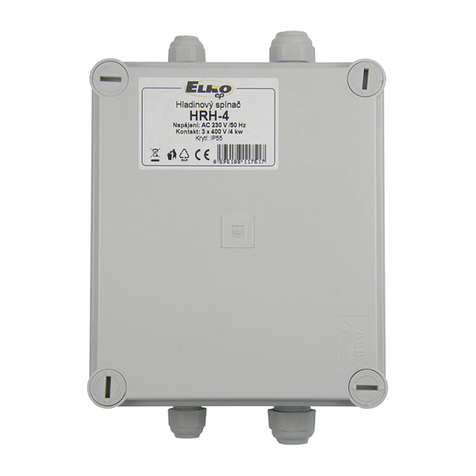
Elko HRH-4 User manual

Elko

Elko HRH-4 User manual

Elko iNels SA3-04M User manual

Elko

Elko iNels SA3-04M User manual

Elko HRH-4 User manual

Elko

Elko HRH-4 User manual

Elko RFDEL-76M User manual

Elko

Elko RFDEL-76M User manual

Elko iNels DA2-22M User manual

Elko

Elko iNels DA2-22M User manual

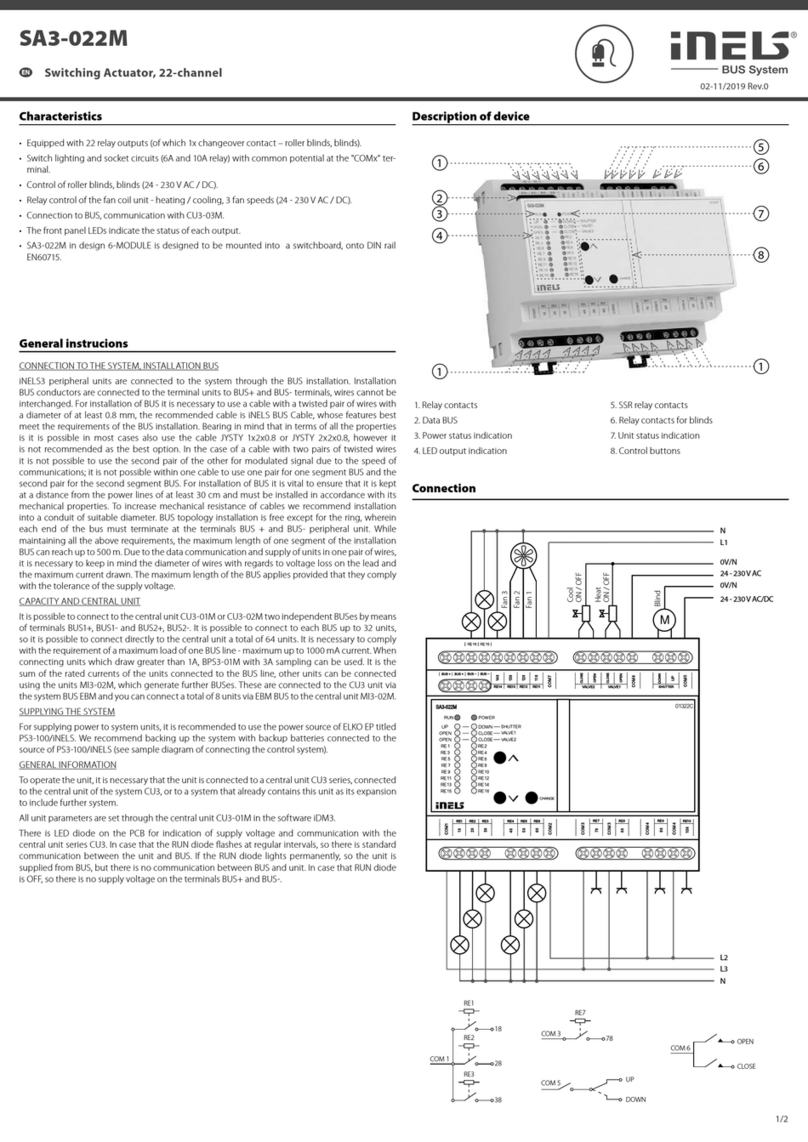
Elko iNels SA3-022M User manual

Elko

Elko iNels SA3-022M User manual

Elko RFJA-12B/230V User manual

Elko

Elko RFJA-12B/230V User manual

Elko iNels BPS3-01M User manual

Elko

Elko iNels BPS3-01M User manual

Elko iNELS SA2-012M Simple manual

Elko

Elko iNELS SA2-012M Simple manual

Elko RFWB-20/G User manual

Elko

Elko RFWB-20/G User manual

Elko LIC-2 User manual

Elko

Elko LIC-2 User manual

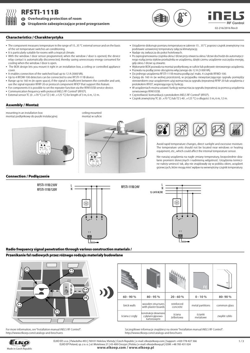
Elko iNELS RFSTI-111B User manual

Elko

Elko iNELS RFSTI-111B User manual

Elko inels RFSTI-11B User manual

Elko

Elko inels RFSTI-11B User manual

Elko LIC-2 User manual

Elko

Elko LIC-2 User manual

Elko RFDAC-71B User manual

Elko

Elko RFDAC-71B User manual

Elko LIC-1 User manual

Elko

Elko LIC-1 User manual

Elko iNELS AirSLC-100NB/NEMA/DALI User manual

Elko

Elko iNELS AirSLC-100NB/NEMA/DALI User manual

Elko RFSA-61B User manual

Elko

Elko RFSA-61B User manual

Popular Controllers manuals by other brands

White Rodgers 1131 installation instructions

White Rodgers

White Rodgers 1131 installation instructions

Noark Ex9S80 manual

Noark

Noark Ex9S80 manual

FlowLine Smart-Trak AV23 Series manual

FlowLine

FlowLine Smart-Trak AV23 Series manual

Wilo CONTROL BOX CE+ WeH Installation and operating instructions

Wilo

Wilo CONTROL BOX CE+ WeH Installation and operating instructions

Huviron SK-AR13 user manual

Huviron

Huviron SK-AR13 user manual

Air Lift Load CONTROLLER I 25655 installation guide

Air Lift

Air Lift Load CONTROLLER I 25655 installation guide

Avonic CM-CON100 user manual

Avonic

Avonic CM-CON100 user manual

Aruba Networks 3000 Series manual

Aruba Networks

Aruba Networks 3000 Series manual

AXIOMATIC AX141120 user manual

AXIOMATIC

AXIOMATIC AX141120 user manual

VIPA System 300S manual

VIPA

VIPA System 300S manual

GE EntelliPro ES Series Installation and instruction manual

GE

GE EntelliPro ES Series Installation and instruction manual

Hacker JETIBOX manual

Hacker

Hacker JETIBOX manual

artisan 5400-ES user manual

artisan

artisan 5400-ES user manual

Siemens OpenAir GIB132.1P Technical instructions

Siemens

Siemens OpenAir GIB132.1P Technical instructions

Beckett AquaSmart Quick Tutorial

Beckett

Beckett AquaSmart Quick Tutorial

ABB Jocab Safety Vital 2 Operating	 instruction

ABB

ABB Jocab Safety Vital 2 Operating instruction

Advanced Illumination DCS Series user manual

Advanced Illumination

Advanced Illumination DCS Series user manual

SDC EH SERIES installation instructions

SDC

SDC EH SERIES installation instructions

manuals.online logo
manuals.online logoBrands
  • About & Mission
  • Contact us
  • Privacy Policy
  • Terms and Conditions

Copyright 2025 Manuals.Online. All Rights Reserved.