7
Technical Support: +44(0)23 9269 6638 (option 3) PAK200583_02C Jan 2021 ©2019 ELMDENE INTERNATIONAL LTD
Standby Battery
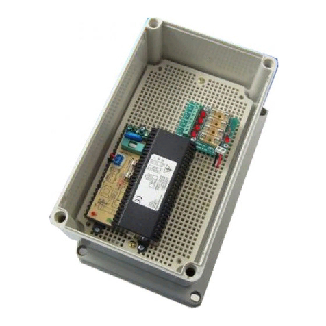
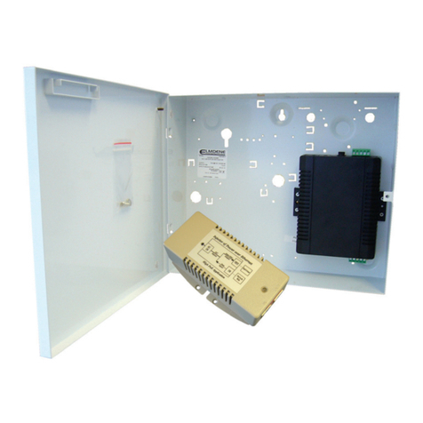
9) Mount the appropriate batteries as shown in Figure 2. Where a dual box solution is used all cabling
between the two boxes should be routed to use separate case entry/exit holes from other cabling and use
suitable bushes to protect the cables.
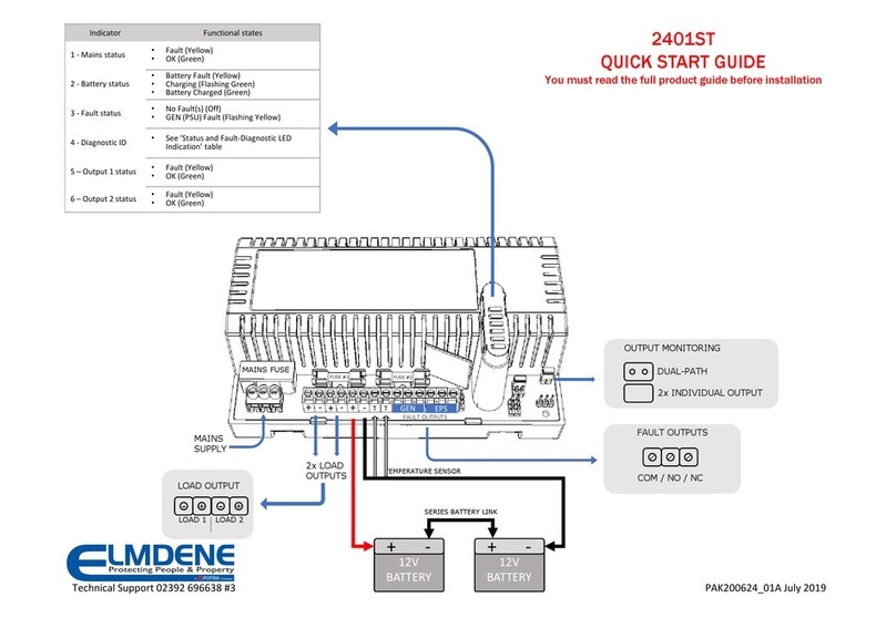
10) With mains disconnected, connect the two 12 V standby batteries in series using the single cable provided.
Connect the negative of one battery to the positive of the other. See Figure 3.
CAUTION –DO NOT CONNECT the two remaining (free) battery terminals to each other!
11) Connect the PCB terminals Batt+ and Batt–to the free Positive and Negative terminals of the batteries
using the cables provided. See Figure 2 and 3. With the cable pair ALREADY screwed into the battery
terminals the FINAL connection MUST be to the battery itself.
12) CAUTION –significant energy can be released from an SLA battery. When connecting the last battery
lead, take extreme care to attach the cable ONLY to the correct terminal. Avoid shorting it to any other
terminal or conducting surface.
13) Connect the battery temperature sensor (two white wires) to the PCB terminals Temp Sense. See Figure 4.
Wires can be connected either way around.
14) Verify that the yellow Fault LED does not flash (battery connection detected). Verify that the remote PSU
Fault monitor shows a closed contact.
15) Disconnect the mains power. Verify that the green Mains LED extinguishes and the Yellow Fault LED starts
to pulse (indicating that the PSE is running from its standby batteries).
16) If connected, verify that the EPS Fault monitor shows an open contact and the GEN PSU Fault monitor
shows a closed contact.
17) Verify that the standby batteries are now driving (supporting) the system load. Perform a full functional
test of system including full alarm condition Note: ensure batteries have sufficient charge to support the
system under full load.
Final
18) Reconnect the mains. Verify that the green Mains LED illuminates and the yellow Fault LED extinguishes.
19) If connected, verify that the EPS Fault monitor shows a closed contact and the GEN PSU Fault monitor
shows a closed contact.
20) Disconnect one of the battery leads, ensuring that no exposed section of conductor or connector is
allowed to contact exposed metal-work, other PSE terminals, or other battery terminals.
21) Verify that, in less than 1 minute, the yellow Fault LED starts to flash, and that the orange Diagnostic LED
flashes in a 2 pulse repeating pattern, (indicating that battery disconnection was detected).
22) Reconnect the battery lead and, after approximately 3 s, verify that that the Fault LED does not flash.
(Audible click can be heard as the battery relay closes, then a second click while the charger is tested.)
23) Note: If it is necessary to obtain confirmation of charging current; between steps 18 and 20, an ammeter
can be placed in series with the battery leads. Continue to observe caution with all exposed conductors
when inserting or removing the meter and when restoring normal battery wiring.
