ELTEX WB-2P-LR5 User manual

IP address:192.168.1.1
Username:admin
Password:password
User station
WB-2P-LR5
User manual
Firmware version2.3.0

WB-2P-LR5. User manual
2
Contents
1 Introduction .................................................................................................................................................. 4
1.1 Annotation.................................................................................................................................................4
1.2 Symbols.....................................................................................................................................................4
2 Device description ....................................................................................................................................... 5
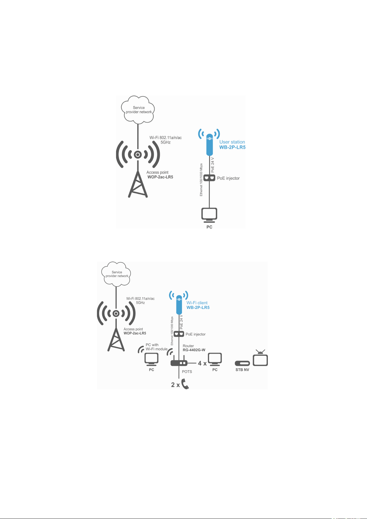
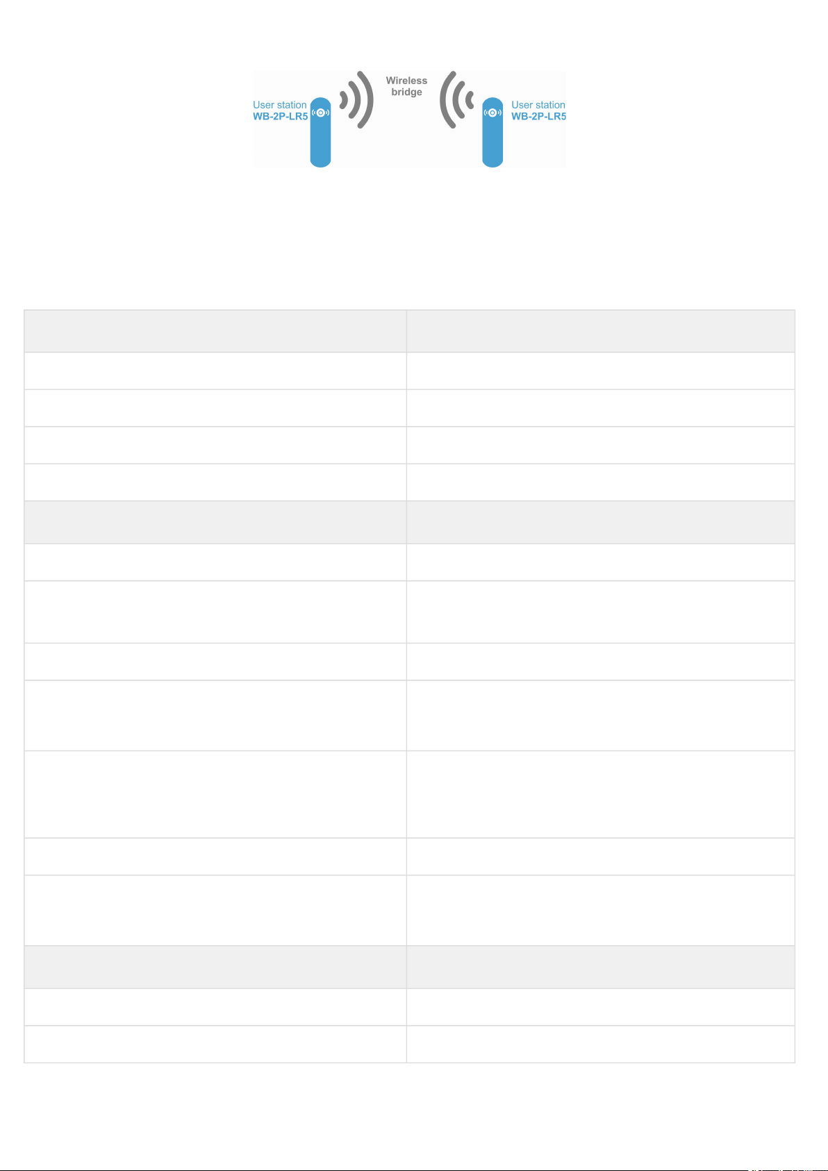
2.1 Purpose .....................................................................................................................................................5
2.2 Device specification..................................................................................................................................5
2.3 Technical features ....................................................................................................................................7
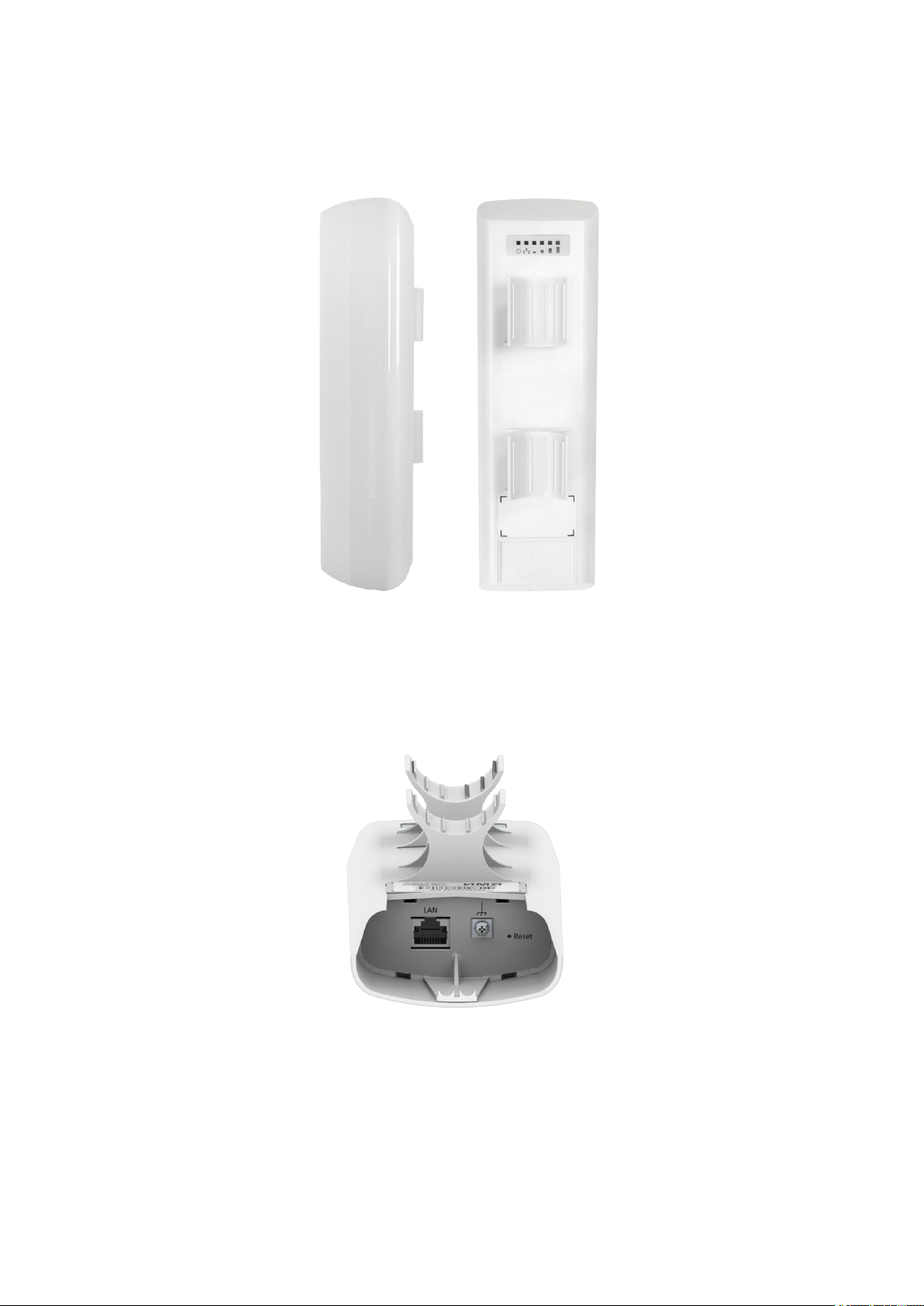
2.4 Design........................................................................................................................................................9
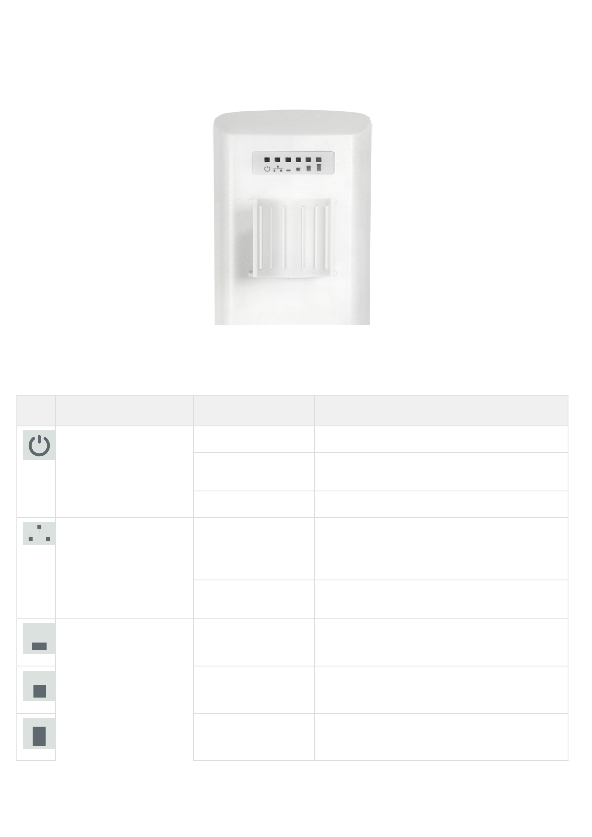
2.5 Light indication........................................................................................................................................10
2.6 Reset to the default settings ..................................................................................................................11
2.7 Delivery package.....................................................................................................................................11
3 Installation order........................................................................................................................................ 12
3.1 Safety rules..............................................................................................................................................12
3.2 Installation recommendations ...............................................................................................................12
3.3 WB-2P-LR5 mounting..............................................................................................................................12
3.3.1 Pre-tuning ............................................................................................................................................ 12
3.3.2 Mounting algorithm ............................................................................................................................ 12
3.4 Switching on............................................................................................................................................15
3.5 Wi-Fi antenna alignment.........................................................................................................................15
4 Device management via WEB configurator.............................................................................................. 16
4.1 Getting started ........................................................................................................................................16
4.2 Changing user .........................................................................................................................................17
4.3 Applying configuration and discarding changes ..................................................................................18
5 Main elements of the WEB interface ........................................................................................................ 19
5.1 The«Monitoring» menu..........................................................................................................................20
5.1.1 The «Internet» submenu..................................................................................................................... 20
5.1.2 The «WDS» submenu.......................................................................................................................... 21
5.1.3 The «Ethernet Ports» submenu.......................................................................................................... 22
5.1.4 The «DHCP» submenu........................................................................................................................ 23
5.1.5 The «ARP» submenu........................................................................................................................... 23
5.1.6 The «PPPoE Relay» submenu ............................................................................................................ 24
5.1.7 The «PPPoE Client» submenu............................................................................................................ 24
5.1.8 The «Device Info» submenu ............................................................................................................... 25

WB-2P-LR5. User manual
3
5.1.9 The «Conntrack» submenu................................................................................................................. 26
5.1.10 The «Routes» submenu ...................................................................................................................... 28
5.2 The «Network» menu..............................................................................................................................29
5.2.1 The «Internet» submenu..................................................................................................................... 29
5.2.2 The «Radio» submenu ........................................................................................................................ 38
5.2.3 The «LAN» submenu........................................................................................................................... 40
5.2.4 The «MAC address Management» submenu.................................................................................... 41
5.2.5 The «Local DNS» submenu ................................................................................................................ 42
5.2.6 The «NAT and Port Forwarding» submenu ....................................................................................... 43
5.2.7 The «Firewall» submenu..................................................................................................................... 45
5.2.8 The «Routes» submenu ...................................................................................................................... 47
5.2.9 The «Dynamic DNS» submenu........................................................................................................... 48
5.2.10 The «SNMP» submenu ....................................................................................................................... 49
5.3 The «IPTV» menu ....................................................................................................................................50
5.3.1 The «IPTV» submenu.......................................................................................................................... 50
5.4 The «System» menu................................................................................................................................52
5.4.1 The «Time» submenu ......................................................................................................................... 52
5.4.2 The «Access» submenu...................................................................................................................... 53
5.4.3 The «Log» submenu............................................................................................................................ 54
5.4.4 The «Passwords» submenu ............................................................................................................... 56
5.4.5 The «Configuration management» submenu.................................................................................... 57
5.4.6 The «Firmware Upgrade» submenu................................................................................................... 58
5.4.7 The «Reboot» submenu...................................................................................................................... 59
5.4.8 The «Autoprovisioning» submenu ..................................................................................................... 59
5.4.9 The «Advanced» submenu ................................................................................................................. 61
6 Configuration Example .............................................................................................................................. 63
7Spectrum Analyzer.................................................................................................................................... 65
8 Device automatic DHCP-based update algorithm ................................................................................... 66
9 System recovering after firmware update failure .................................................................................... 69
10 Appendix A. Launch user script when starting the system..................................................................... 70
11 Appendix B. Antenna Patterns .................................................................................................................. 71

WB-2P-LR5. User manual
4
1 Introduction
1.1 Annotation
Modern tendencies of telecommunication development necessitate operators to search for the most optimal
technologies, allowing you to satisfy drastically growing needs of subscribers, maintaining at the same time
consistency of business processes, development flexibility and reduction of costs of various services provision.
Wireless technologies are spinning up more and more and have paced a huge way for a short time from unstable
low-speed communication networks of low radius to broadband networks equitable to speed of wired networks
with high criteria for the quality of provided services.
WB-2P-LR5 is a user station designed for connection to Wi-Fi access network which might be constructed using
base stations within long distances. The case of WB-2P-LR5 is sealed, that is allows to install the device outdoor
with different climate conditions.
This manual specifies intended purpose, main technical parameters, design, installation procedure, safe operation
rules and installation recommendations forWB-2P-LR5.
1.2 Symbols
Notes and warnings
Notes contain important information, tips or recommendations on device operation and setup.
Warnings are used to inform the user about harmful situations for the device and the user alike, which
could cause malfunction or data loss.

WB-2P-LR5. User manual
5
•
•
•
•
•
•
•
•
•
•
•
•
•
•
•
•
•
•
•
•
•
2 Device description
2.1 Purpose
User station WB-2P-LR5 (herein after «the device») is designed for access provision to secure wireless network.
The device provides access to up-to-date interactive services: Internet, IPTV, VoIP.
WB-2P-LR5 connects to a base station via Wi-Fi technology and operates at 5 and 6 GHz (the frequency range –
5830-6150 MHz – is supported on WB-2P-LR5 rev.B and WB-2P-LR5 rev.C). The device is supposed to operate
with WOP-2ac-LR5. WB-2P-LR5 might be also used for wireless bridge organization.
WB-2P-LR5 supports up-to-date requirements to service quality and allows transmitting more important traffic in
higher priorities queues. Prioritization is based on QoS technologies: CoS (special tags in VLAN packet field) and
ToS (tags in IP packet field).
The device is capable to operate in wide temperature range and in high-humidity conditions (parks, factories,
stadiums, etc.).
Power to the device is supplied via PoE technology 24V.
2.2 Device specification
Interfaces:
LAN: 1 portEthernet RJ-45 10/100/1000BASE-T;
WLAN: IEEE 802.11a/n/ac;
Service Wi-Fi 2.4 GHz 802.11b/g/n(short-range interface for adjustment and device setup during the
installation period)1
The power is supplied via PoE injector 24V connected to 220V network.
1For WB-2P-LR5 rev.C.
Network functions:
operating in bridge and router modes;
operating in «Wi-Fi Station»and «Wireless bridge» modes;
support for VLAN Trunk;
support for Management VLAN;
support for General VLAN;
support for Transparent Mode;
static routing;
support for Transparent wireless bridge function;
support for PPPoE client;
time synchronization via NTP;
support for static address and DHCP (DHCP client on WAN side, DHCP server on LAN side);
support for DNS;
support for D-DNS;
support for NAT;
support for UPnP;
firewall;
support for cloning of MAC address on WAN interface;
support for quality of service mechanisms (QoS through DSCP and 802.1P).
Do not use an injector with voltage different from 24V so as not to break down the device!

WB-2P-LR5. User manual
6
•
•
•
•
•
support for IPTV functions (IGMP-proxy, UDP-to-HTTP proxy);
firmware update via web interface;
support for DHCP-based autoprovisioning;
support for TR-069;
remote monitoring, configuration and setup: SNMP, web interface, Telnet, SSH.
The figures below illustrate applications schemes of WB-2P-LR5.
Functional scheme of using WB-2P-LR5 without router
Functional scheme of using WB-2P-LR5 with router

WB-2P-LR5. User manual
7
Functional scheme of using WB-2P-LR5 for wireless bridge organization
2.3 Technical features
Table 1 shows main specifications of the device.
Table 1 — Main specifications
LAN Ethernet interface parameters
Number of ports 1
Electrical connector RJ-45
Data rate, Mbps 10/100/1000, auto-negotiation
Standards BASE-T
Wireless interface parameters
Standards 802.11a/n/ac
Frequency range, MHz 5180–5825 MHz
5180-6150 MHz (for WB-2P-LR5 rev.B, WB-2P-LR5 rev.C)
Modulation BPSK, QPSK, 16QAM, 64QAM, 256QAM
Speed of data transmission, Mbps 802.11a:up to 54 Mbps
802.11n:up to 300 Mbps
802.11ac:up to 867 Mbps
Maximum output power of the transmitter 5–6 GHz:
24 dBm (for WB-2P-LR5, WB-2P-LR5 rev.B)
28 dBm (forWB-2P-LR5 rev.C)
Receiver sensitivity 5-6 GHz:-94 dBm
Security 64/128/152- bit WEP encryption, WPA/WPA2,
centralized authorization via RADIUS server (WPA/WPA2
Enterprise)
Antenna's parameters
Gain 2x12 dBi
Polarization dualpolarized antenna

WB-2P-LR5. User manual
8
Beam angle (horizontal polarization) 60°
Beam angle (horizontal polarization) 15°
SWR 2.0:1
Impedance 50 Ohm
Front to back ratio > 20 dB
Control
Remote control Web interface, Telnet, SSH, SNMP (monitoring), TR-069
Access restriction by password
General parameters
Processor Realtek RTL8197FS 1 GHz
RAM 128 MB
Flash 32 MB
Power supply PoE 24 V
Power consumption no more than 8 W
range of operation temperatures from -45 to +65°С
Operating humidity up to 95%
Ingress Protection Marking IP54
Dimensions 80x66x282 mm
Weight 0,35 kg

WB-2P-LR5. User manual
9
2.4 Design
WB-2P-LR5 housed in a plastic case, industrial version. The size of the device: 80x66x282 mm.
The layout of WB-2P-LR5 is shown in the figure below.
WB-2P-LR5 layout
LAN port 10/100/1000Base-T (RJ-45 connector) for local network connection and power supply via PoE, a
grounding connector(for WB-2P-LR5 rev.C ) and the button for resetting to factory settings («Reset») are located
on the bottom panel of the device.
WB-2P-LR5 bottom panel elements

WB-2P-LR5. User manual
10
2.5 Light indication
The light indication panel of WB-2P-LR5 is shown below.
WB-2P-LR5 light indication panel
The current state of the device is shown with the help of light indicators located on the back panel of WB-2P-LR5.
The list of indicators and their description is shown in the table below.
Table 2 – Description of rear panel LED indicators
Indicator Indicator's state Description
Power – power and
operation status indicator
solid green the device power supply is enabled, normal operation
solid orange the device is loaded but IP address is not received via
DHCP
solid red the device is loading
LAN – LAN interface
indicator
solid green (10, 100
Mbps)/
solid orange (1000
Mbps)
the channel between LAN interface of WB-2P-LR5 and
connected device is active
flashes packet data transmission between LAN interface of
WB-2P-LR5 and connected device
WLAN – received signal
strength indicator (RSSI)
solid red the device is connected to a base station. The base
station signal level is more than -94 dBm
solid orange the device is connected to a base station. The base
station signal level is more than -80 dBm
solid green the device is connected to a base station. The base
station signal level is more than -70 dBm

WB-2P-LR5. User manual
11
1.
2.
•
•
•
•
•
•
•
•
Indicator Indicator's state Description
solid green the device is connected to a base station. The base
station signal level is more than -60 dBm
none of the indicators is
on
the device is not connected to the base station
2.6 Reset to the default settings
There are two ways to reset the device to factory settings:
Using «Reset» button on the device. When the device is loaded, press and hold«Reset» button located on
the bottom panel (approximately 10–15 seconds) until «Power» indicator is flashing orange;
Using PoE injector supplied with the device. When the device is loaded, press and hold«RST» button of the
injector (approximately 10–15 seconds) until«Power» indicator of WB-2P-LR5 is flashing orange.
Device will be rebooted automatically. DHCP client will be launched by default. If the address is not received via
DHCP the device will have IP address —192.168.1.1,subnet mask —255.255.255.0; User Name/Password to
access via Web interface: admin/password.
2.7 Delivery package
The basic supply package of WB-2P-LR5 includes:
User station WB-2P-LR5;
Mounting kit: 2 clamps for attaching;
PoE injector 24 V;
Patch cord RJ-45, 5e cat. 1.5 m;
Cord for europlug - C13-F-1.8 m;
Sheet with light indication description;
Conformity certificate;
Technical passport.
A bracket with horizontal and vertical adjustment might be included to the supply package upon a request.

WB-2P-LR5. User manual
12
1.
2.
3.
4.
5.
6.
7.
8.
1.
2.
3.
4.
5.
3 Installation order
This section defines safety rules, installation recommendations, setup procedure and the device starting
procedure.
3.1 Safety rules
Do not open the device case. There are no user serviceable parts inside.
Do not install the device during a thunderstorm. There is a risk of lightning stroke.
You must follow requirements for voltage, current and frequency specified in the user manual.
Measuring devices and computer must be grounded before connecting to the device. The electric potential
differnce between devices' cases should not exceed 1 V.
Make sure that all the cables are intact and they are reliably attached to connectors.
You should satisfy established standards and requirements for working at height during the device
installation on the high-rise constructions.
The device exploitation should be performed by speciallyprepared engineering and technical personnel.
Connect only to operational service equipment.
3.2 Installation recommendations
Recommended location for device installation: communications mast/pole.
Before you install and enable device, check the device for visible mechanical defects. If defects are
observed, you should stop the device installation, draw up corresponding act and contact the supplier.
Install the device vertically on communications mast or pole in the way that the LAN port is pointed down.
In order to provide better receiving signal level, the sectoral antenna of a base station should be in line of
sight of WB-2P-LR5. You may achive the highest signal level by antenna alignment with the help of RSSI
indicators.
The transmitting part of the device is located on the other side from brackets. This area should be directed
to base station sectoral antenna.
After adjusting, make sure that level of the received signal from the base station should be no more than -65 ÷ -70
dBm. Decreasing this level up to -75 dBm is permitted if it does not involve the use of VoIP, streaming video and
other traffic that is sensitive to losses in a wireless network.
3.3 WB-2P-LR5 mounting
3.3.1 Pre-tuning
Before installing, proceed pre-tuning of the device (see sectionConfiguration example). For this, power on the
device (paragraph 2-7, sectionMounting algorithm) and follow the instructions given in the sectionConfiguration
example. Make sure that the user station connects required wireless network: RSSI indicators should be on.
3.3.2 Mounting algorithm
1.Install the device on communications mast/pole pointing LAN port down as it is shown on the figure below.
Attach the device using clamps supplied in the device package. Comply the safety rules and
recommendations given in Safety rulesandInstallation recommendations.
Install the device on communications mast/pole so that the device is directed to base station sectoral
antenna as much as possible. There must also be direct visibility to the base station.

WB-2P-LR5. User manual
13
2. Remove the bottom cover which close LAN-port.Ground the device through a grounding connector (for
WB-2P-LR-5 rev.C).
3. Connect Ethernet cable to LAN port.
4. Close the bottom cover.
5. Connect Ethernet cable connected to WB-2P-LR5 to PoE port of injector.

WB-2P-LR5. User manual
14
6. Connect Ethernet cable of your LAN network or PC to LAN port of PoE injector.
7. Connect PoE injector to 220V socket with the help of power line cord.
8. Align the position of the device for best signal level receiving. The level of received signal is shown by the
indication located on the back panel of the device.
9. Fasten the clamps.

WB-2P-LR5. User manual
15
1.
2.
3.
1.
2.
3.
3.4 Switching on
Plug the injector into 220 V outlet. Connect a PC to LAN port of the injector.
WB-2P-LR5 loads in a minute after switching on. Connect to the web configurator of WB-2P-LR5 through a
browser.
Network configuration is described in The 'Network' menusection.
3.5 Wi-Fi antenna alignment
For ease of antenna alignment the Service Wi-Fi is implemented in the device (only for WB-2P-LR5 rev.C). It allows
to connect the wireless client to the "EltexWiFi" SSID (2.4 GHz frequency band) and align antennas using data
ofmonitoring of the connection parameters of the subscriber station WB-2P-LR5 with the base station in WEB
interface.
Connect the smartphone to a Wi-Fi network using the EltexWiFi SSID.
Set the following connection settings on the smartphone: Static IP address– 192.0.2.X; netmask–
255.255.255.0; gateway–192.0.2.1.
Open the browser aand enter the address192.0.2.1:8080.The alignment tab will be displayed, where the
signal level from the station to which the WB-2P-LR5 is connected is displayed in real time:
4. Perform the alignment with maximum RSSI.
5. After alignment, you must disable the Service Wi-Fi.
Service Wi-Fi enable/disable through the device’s web configurator is described in the 'Advanced settings'
submenu.
IP address by default: 192.168.1.1.
Username:admin, password:password.

WB-2P-LR5. User manual
16
1.
2.
4 Device management via WEB configurator
4.1 Getting started
To start, you need to connect the device through a browser:
Open a web browser(web-page explorer), for example, Firefox, Opera, Chrome.
Enter IP-address of the device to the browser address line.
If connection is successful, request form with user name and password will be displayed on a browser window.
3. Enter your username into ‘Login’ and password into ‘Password’ field. Click the ‘Log in’ button. Device Web
configurator home page will be opened in the browser window.
IP address by default:192.168.1.1,subnet mask: 255.255.255.0. The device is capable to obtain an IP
address via DHCP.
Factory settings:login:admin, password:password.

WB-2P-LR5. User manual
17
•
•
4.2 Changing user
There are two user types for the device:adminand viewer:
admin(password by default:password) has the full access to the device: read/write any settings, full device
status monitoring.
viewer may only view full device configuration without editing privileges; may access full device status
monitoring.
When you click the Logout button, the current user session will be terminated; login window will be displayed:
To change the access, you should specify the corresponding username and password and click Log in button.
You may select languages on the top-right of the page. Russian and English languages are available.

WB-2P-LR5. User manual
18
1.
2.
4.3 Applying configuration and discarding changes
Applying configuration
The visual indication of the settings applying is realized in the web interface.
The visual indication of the settings applying:
Image State description
After pressing «Apply», the process of settings saving to device memory is
launched. This is indicated by the icon in the tab name and on the Apply
button.
If the setting are saved successfully, the iconwill be displayed next to the
tab name and on «Apply» button.
If any parameter value have been set incorrectly, the error notification with
description will be displayed after pressing «Apply» button. The mark will be
displayed next to the tab name and on «Apply» button.
The 'Apply' button in the menu .
Discarding changes
The button for discarding changes appears as follows: .
Press «Apply» to save configuration to flash memory and apply new settings. All the settings come
into operation without device rebooting.
You can discard changes only before pressing «Apply» button. If you press «Apply» button, all the
changed parameters will be applyed and saved to device memory. You will not be able to return to
previous configuration after pressing «Apply».

WB-2P-LR5. User manual
19
1.
2.
3.
4.
5.
6.
5 Main elements of the WEB interface
The figure below shows navigation elements of the web configurator.
The user interface is divided into seven areas:
Username, which was used to enter the system and «logout» button to finish the user session.
Menu tabs which contain submenu tabs are divided into categories:Network, System.
Submenu tabs manage the settings field below.
Settings field, which is based on the user select. The field is dedicated to view device settings and setting
configuration data.
Configuration management buttons, the detailed description is given in sectionApplying configuration and
discarding changes.
Information field. The field contain information on firmware version and web interface version.

WB-2P-LR5. User manual
20
•
•
•
•
•
•
•
5.1 The«Monitoring» menu
To move to the system monitoring mode, select «Monitoring» on the left panel.
5.1.1 The «Internet» submenu
In the Internet submenu, you may view main network parameters of the device.
Internet Connection
Network connection –the parameter shows the type of connection to the external network;
Connection Status–the parameter shows state of connection to the external network;
SSID –a name of wireless network, to which the device is connected;
Access Protocol – a protocol which is used for access to the external network;
IP Address– device IP address in the external network;
Link Capacity – parameter that reflects the effectiveness of the use of a modulation by the device on the
transmission. It is calculated based on the number of packets transmitted on each modulation, and the
reduction factors. The maximum value is 100% (means that all packets are transmitted at maximum
modulation for the maximum nss type supported by the device). The minimum value is 2% (in the case
when the packets are transmitted to the modulation nss1mcs0 for the device with MIMO 3x3 support). The
parameter value is calculated for the last 10 s;
Link Quality – parameter that displays the status of the link, calculated based on the number of sent
retransmit packets. The maximum value is 100% (all transmitted packets were sent on the first attempt), the
Some pages are not updated automatically. To obtain current state of the device, press .
Other manuals for WB-2P-LR5
1
Table of contents
Other ELTEX Wireless Access Point manuals

ELTEX
ELTEX WB-15-W User manual

ELTEX
ELTEX WB-2P-LR2 User manual

ELTEX
ELTEX WOP-2ac User manual

ELTEX
ELTEX WEP-2ac Smart User manual

ELTEX
ELTEX WOP-2L User manual

ELTEX
ELTEX WEP-1L User manual

ELTEX
ELTEX WOP-12ac User manual

ELTEX
ELTEX WEP-3ax User manual

ELTEX
ELTEX WOP-20L User manual

ELTEX
ELTEX WEP-2ac-Z User manual

ELTEX
ELTEX WOP-12ac-LR User manual

ELTEX
ELTEX WEP-2ac Smart User manual

ELTEX
ELTEX WEP-30L User manual

ELTEX
ELTEX WEP-200L User manual

ELTEX
ELTEX WEP-2ac Smart User manual

ELTEX
ELTEX WOP-12ac-LR User manual

ELTEX
ELTEX WEP-2L User manual

ELTEX
ELTEX WOP-2ac Installation guide

ELTEX
ELTEX WOP-12ac User manual

ELTEX
ELTEX WOP-12ac User manual