2
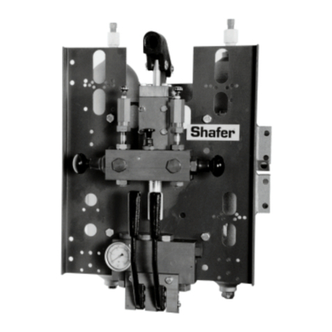
ANDERSON GREENWOOD TYPE 727 DUAL PILOT MANIFOLD
INSTALLATION AND MAINTENANCE INSTRUCTIONS
1 GENERAL DESCRIPTION
Operation
The Type 727 pilot operated safety valve uses
the principle of loading the larger area of a
differential area piston with line pressure to
hold the piston closed up to set pressure.
Service configurations (see Figure 1)
The 727 assembly is shipped in one of two main
valve configurations depending on whether it
is to be applied to steam or air/gas service.
Thepilot assembly is identical for both services.
1. Steam service configuration
Valves for steam service are identified
externally by the presence of tubing
connecting the unloader valve in the
manifold assembly to the main valve
outlet. When the pilot actuates, it vents the
small volume of steam in the dome of the
unloader causing the unloader to open.
The unloader is connected directly to the
main valve dome chamber and allows the
pressure in the dome chamber to vent
intothe outlet of the main valve.
2. Air/gas service configuration
Valves for air/gas service are identified
externally by the lack of tubing from the
manifold to the main valve outlet. The
unloader piston has been removed and a
cap is installed in the unloader cavity in
the manifold. The pilot vents main valve
dome pressure directly to the atmosphere.
An NPT plug is installed in the unloader
discharge port in the main valve outlet.
Internally, the main valve piston radial hole
used for steam service either is eliminated
or plugged permanently for air/gas service.
Installed in the top groove of the air/gas
piston is a special piston ring with a low
leakage end joint design. Installed in
the pressure sense port in the cap is a
pressurespike snubber.
WARNING
The protection and safety of equipment, property
and personnel depends on the proper operation
of the safety valves described in this manual. All
Emerson Flow Control safety valves should be
kept in proper working condition in accordance
with the manufacturer’s written instructions.
Periodic testing and maintenance by the user of
this equipment is essential for reliable and safe
valveoperation.
All installation, maintenance, adjustment, repair
and testing performed on safety valves should
be done by qualified technicians having the
necessary skills and training adequate to perform
such work. All applicable codes and standards,
governing regulations and authorities should be
adhered to when performing safety valve repair.
No repair, assembly, adjustment or testing
performed by other than Emerson Flow Control
or its authorized assemblers and representatives
shall be covered by the warranty extended by
Emerson Flow Control to its customers. The
user should use only original, factory supplied
OEM parts in any maintenance or repair activity
involving this product.
This maintenance manual is provided as a general
guide for the repair and maintenance of the
safety valves described herein. It is not possible
to describe all configurations or variations
with such equipment. The user is advised to
contact Emerson Flow Control or its authorized
assemblers and representatives for assistance
in situations that are not covered adequately or
described in this manual.
Before removing a safety valve for maintenance,
ensure that the system pressure has been fully
depressurized. If an isolation block valve is used,
ensure that any trapped fluid between the block
valve and the safety valve is vented safely.
Before disassembling the safety valve ensure
that the valve has been decontaminated from
any harmful gasses or fluids and that it is at a
safe temperature range for handling. Fluids can
be trapped in the dome space of pilot operated
safetyvalves.
Before installation, the Installation and
Operational Safety Instructions should be read
fully and understood. These Instructions may
be requested from the factory or are available
atvalves.emerson.com.
Onrising system pressure, the pilot actuates at
set pressure, venting pressure from the main
valve dome chamber. When the main valve
dome pressure is reduced to 40% of system
pressure, the main valve disk lifts off the nozzle
seat, thereby venting system pressure through
the outlet.
When system pressure drops by 5 to 7% of set,
the pilot closes, allowing system pressure to
recharge the main valve dome causing the disk
to reseat on the nozzle.
When operating below set pressure, the inlet
and main valve dome pressures are equal so
that the seating force on the main valve seat is
equal to the system pressure times the seating
area. Since the seat load increases with system
pressure, the main valve maintains premium
seat tightness up to set pressure.
