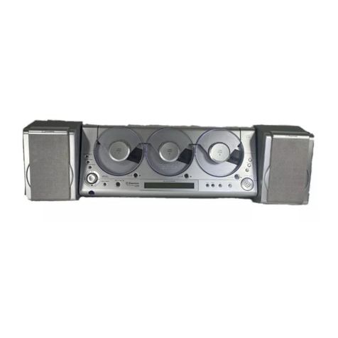
Emerson MS3110 User manual

OWNER'SMANUAL
MS3110
Visitourweb siteatwww.emersonradio.com
HOMEAUDIOSYSTEM
with3-CD Changer,
DigitalAM/FMReceiver
and RemoteControl
MS3110_112106.p65 22/11/2006, 11:4844

1
TO PREVENT FIRE OR SHOCK HAZARD, DO NOT USE THIS PLUG WITH AN
EXTENSION CORD, RECEPTACLE OR OTHER OUTLET UNLESS THE BLADES
CAN BE FULLY INSERTED TO PREVENT BLADE EXPOSURE. TO PREVENT FIRE
ORSHOCKHAZARD,DONOTEXPOSETHISAPPLIANCETORAINORMOISTURE.
IMPORTANTSAFETYINSTRUCTIONS
1.) Read these instructions. Keep these instructions. Follow all instructions. Heed all warnings.
2.) Do not use this apparatus near water.
3.) Clean only with dry cloth.
4.) Do not block any ventilation openings. Install in accordance with the manufacturer’s instructions.
5.) Do not install near any heat sources such as radiators, heat registers, stoves, or other apparatus
(including amplifiers) that produce heat.
6.) Do not defeat the safety purpose of the polarized or grounding-type plug. A polarized plug has two
blades with one wider than the other. A grounding type plug has two blades and a third grounding
prong. The wide blade or the third prong is provided for your safety. If the provided plug does not
fit into your outlet, consult an electrician for replacement of the obsolete outlet.
7.) Protect the power cord from being walked on or pinched particularly at plugs, convenience
receptacles, and the point where they exit from the apparatus.
8.) Only use attachments / accessories specified by the manufacturer.
9.) Unplug this apparatus during lightning storms or when unused for long periods of time.
10.) Refer all servicing to qualified service personnel. Servicing is required when the apparatus has
been damaged in any way, such as power-supply cord or plug is damaged, liquid has been spilled
or objects have fallen into the apparatus, the apparatus has been exposed to rain or moisture,
does not operate normally, or has been dropped.
11.) This appliance shall not be exposed to dripping or splashing water and no object filled with liquids
such as vases shall be placed on the apparatus.
12.) Use only with the cart, stand, tripod, bracket, or table specified by the
manufacturer, or sold with the apparatus. When a cart is used, use caution
when moving the cart/apparatus combination to avoid injury from tip-over.
13.) Do not overload wall outlet. Use only power source as indicated.
14.) Use replacement parts as specified by the manufacturer.
15.) The product may be mounted to a wall only if recommended by the manufacturer.
16.) Upon completion of any service or repairs to this product, ask the service technician to
perform safety checks.
!
CAUTION
RISK OFELECTRICSHOCK
DONOTOPEN
The lightning flashwitharrow-
head symbol,withinan equi-
lateraltriangleisintended to
alertthe usertothe presence
ofuninsulated‘dangerousvoltage’
withinthe product’s enclosure
thatmaybe ofsufficient
magnitude toconstitutearisk
ofelectricshock topersons.
The exclamation pointwithin
an equilateraltriangleisin-
tended toalertthe userto
the presenceofimportant
operating and maintenance
(servicing)instructionsin
the literatureaccompany-
ing the appliance.
WARNING:TOREDUCETHE
RISK OFELECTRICSHOCK
DONOTREMOVE COVER
(ORBACK),NOUSER
SERVICEABLEPARTSINSIDE
REFERSERVICINGTO
QUALIFIEDSERVICE
PERSONNEL.
CAUTION
The Caution Marking maybe located at the bottom enclosure of the apparatus.
MS3110_112106.p65 22/11/2006, 11:481
2
BEFOREWEBEGIN
Thankyou forpurchasing thisEmerson audioproduct.The Emerson brand
isyourassuranceofquality,performanceand value.
Ourengineershaveincluded manyusefuland convenientfeaturesinthis
product. Pleasebe suretoread thisOwner’s Manualcompletelytomake
sureyou aregetting the maximumbenefitfromeachfeature.
Thisproductwasmanufactured using the highestqualitycomponentsand
standardsofworkmanship.It wastested byEmerson inspectorsand found
tobe inperfectworking orderbeforeitleft ourfactory.However,thereis
alwaysthechancethatsomeproblemmayoccurbecauseofroughhandling
during shipmenttothe retail storeortothe finalconsumer.
If,afterreadingthismanual,youexperienceanyproblemswiththeoperation
ofthisproduct, pleaserefertothe instructionsforobtaining serviceatthe
end ofthismanual.Emerson and Emerson retailersarecommitted toyour
satisfaction.
Onceagain,thanks forpurchasing thisEmerson audioproduct.
MS3110_112106.p65 22/11/2006, 11:482

3
IMPORTANTNOTES
•Avoidinstalling thisunitinplacesexposed
todirectsunlightorclosetoheatradiating
appliancessuchaselectricheaters,on top
ofotherstereo equipmentthatradiatestoo
muchheat, placeslacking ventilation or
dustyareas,placessubjecttoconstant
vibration and/orhumidormoistareas.
•Donotattempttoclean thisunitwith
chemicalsolventsasthismightdamage the
finish.Useaclean drycloth.
CLASS 1LASERPRODUCT
CLASS 1LASERPRODUCT
APPAREILÁLASERDECLASSE 1
PRODUCTOLASERDECLASE 1
CAUTION
INVISIBLELASERRADIATION
WHENOPENAND INTERLOCKS
DEFEATED.
AVOIDEXPOSURETOBEAM
ThisproductcontainsalowpowerLaserDevice.
FCC Information
Thisequipmenthasbeen tested and found tocomplywiththe limitsforaClass Bdigitaldevice,
pursuanttoPart15 ofthe FCC Rules.Theselimitsaredesigned toprovide reasonableprotection
againstharmfulinterferenceinaresidentialinstallation.Thisequipmentgenerates,uses,and
canradiateradiofrequencyenergyand,ifnotinstalledandusedinaccordancewiththeinstructions,
maycauseharmfulinterferencetoradiocommunications.However,thereisno guarantee that
interferencewill notoccurinaparticularinstallation.If thisequipmentdoescauseharmful
interferencetoradioortelevision reception,whichcan be determined byturning the equipment
off and on,the userisencouraged totrytocorrectthe interferencebyone ormoreofthe following
measures:
•Reorientorrelocatethe receiving antenna.
•Increasethe separation between the equipmentand receiver.
•Connectthe equipmentintoan outleton acircuitdifferentfromthattowhichthe receiveris
connected.
•Consultthe dealeroran experienced radio/TVtechnician forhelp.
ThisdevicecomplieswithPart15 ofthe FCC Rules.Operation issubjecttothe following two
conditions:
(1)Thisdevicemaynotcauseharmfulinterference,and
(2)Thisdevicemustacceptanyinterferencereceived,including interferencethatmay
causeundesired operation.
Changesormodificationsnotexpresslyapproved bythe partyresponsibleforcompliancecould
voidthe user’s authoritytooperatethe equipment.
•Operatecontrolsand switchesasdescribed
inthe manual.
•Beforeturning ‘On’the power,makecertain
thatACpowercordisproperlyinstalled.
•StoreyourCDsinacoolarea toavoid
damage fromheat.
•When moving the set, be suretofirst
disconnecttheACpowercord.
MS3110_112106.p65 22/11/2006, 11:483

4
PREPARATIONFORUSE
Unpacking and Set Up
• This carton contains the main unit, two speakers with removable front panels,
the pedestal stand, and the remote control handset. Carefully remove all the
components from the carton and remove all packing materials form the
components. Make sure nothing is accidentally discarded with the packing
materials.
• Save the carton and packing materials, if possible, in the unlikely event that
this unit ever needs to be returned for service. Using the original carton and
packing material is the only way to properly protect the unit from shipping
damage.
• Remove any descriptive stickers or labels from the front panel of the main unit.
Do not remove any labels or stickers that may be affixed to the back panel of
the main unit or the speakers.
• Note the serial number on the back of the main unit and write this number in
the space provided on the Warranty page of this manual.
• Unwind the AC power cord on the back of the main unit and extend it to its full
length.
• Unwind the FM lead wire antenna on the back of the main unit and extend it to
its full length.
• Unwind the speaker cables on the backs of the speakers and extend them to
their full length.
MS3110_112106.p65 22/11/2006, 11:484

5
Attaching The Pedestal Stand
Note:Thissystemcan be used and operated withorwithoutthe pedestal
stand.If you plan tousethissystemon abookshelf, forexample,you mayfind
thatitismoreconvenienttousewithoutthe pedestalattached.
Howeverthe pedestaldoesprovide extrastabilitysowedo recommend
attaching the pedestalifspaceisnotaproblem.
1.)Placethe mainunitfacedown
on aflatsurfaceasshown.
2.)Position the pedestalbasesothat
the 4guide railson the baseslide
intothe 4slotson the bottomof
the mainunit.
MS3110_112106.p65 22/11/2006, 11:485

6
3.)Returnthe mainunitand the pedestalbasetothe uprightposition and slide the
mainunitall the waybackwardinthe direction ofthe ‘arrow’ontothe pedestal
until the locking tabs‘click’and the mainunitislocked inplace.
If you everneed toremovethe mainunitfromthe pedestal:
1.)Placethe entireunitfacedown
on aflatsurface.
2.)(A)Depress the twopedestal
locking tabstoreleasethe
pedestal.
(B)Slide the pedestalupward
tocompletelyremoveitfrom
the mainunit.
B
A
MS3110_112106.p65 22/11/2006, 11:486

7
Installing TheBack UpBatteries
Thissystemincludesabatteryback up circuitthatwill maintainthe tunerpreset
station memories,the clock time,and the timersettingsinthe eventofatemporary
powerinterruption.The batteryback up systemrequiresthree “AA”batteries,not
included.Pleaseuseawell-knownbrand ofalkaline batteriesforlongestlifeand
mostreliableperformance.
The back-up batterycompartmentislocated on the backside ofthe mainunit.
1.)Press downon the batterydoor-locking tab asshownand removethe door.
2.)Install 3fresh“AA”alkaline batteriesinthe batterycompartment. Besureto
install the batteriescorrectly,according tothe polarity(+/-) markingsinside
the batterycompartment.
3.)Replacethe batterydoor.
Note:The lifeexpectancy ofthe back up batterieswill depend on the number
and the lengthofthe powerinterruptionsthatyou experience.Undernormal
circumstanceswerecommend thatyou replacethe back up batteriesevery12
months.
MS3110_112106.p65 22/11/2006, 11:487

8
RemoteControlBattery
The remotecontrolrequiresone “button-type”3-voltlithium
battery,included.Toextend the lifeofthe originalbattery
wehaveinserted asmall clearplasticspacertab between
the lithiumbatteryand the batteryterminal.
You mustremovethisbatteryspacertab beforeyou can
usethe remotecontrol.
Toremovethe tab,pull itinthe direction ofthe arrowinthe
illustration asshown.
When the operation ofthe remotecontrolbecomesintermittentorunsatisfactory,
replacethe originalbatterywithanew3-voltlithiumbattery.
The batterynumberisCR2025 orequivalent.
Toreplacethe battery,slide the batteryholderoutofthe remotecontrolasshown
inthe following illustration.
Removethe originalbatteryfromthe holderand install anewCR2025 batterywith
the “+”side facing up asshowninthe illustration.Then slide the batteryholder
back intothe remotecontrol.
Dispose oftheoriginalbatteryproperly.Itshouldnotbethrownintoa
fireas thebatterymay explodeifincinerated.Itshouldnotbeleft around
wheresmall childrenorpetsmightplay with,orswallowit.Ifthebattery
isaccidentallyswallowed,contactaphysicianimmediately.
RC-3110
Remove
before use
Remueva
antes de
usar
MS3110_112106.p65 22/11/2006, 11:488

9
RemoteControlStorage
Foryourconveniencewehaveincluded aremotecontrolhandsetholderon the
back cabinetofthe mainunit.
Toavoidmisplacing the handsetwesuggestthatyou storeitinthisholderwhen
notinuse.
BatteryPrecautions
•Replacementofbatteriesmustbe done byan adult.
•Donotmixoldand newbatteries.
•Donotmixalkaline,standard(carbon-zinc)orrechargeable(nickel-cadmium)
batteries.
•The supplyterminalsarenottobe short-circuited.
•Non-rechargeablebatteriesarenottobe recharged.
•Exhausted batteriesaretobe removed.
•Onlybatteriesofthe equivalenttype aretobe used.
•Batteriesaretobe inserted withthe correctpolarity.
•Disposeofbatteriesproperly.Donotdisposeofbatteriesinfire.The batteries
mayexplode orleak.
MS3110_112106.p65 22/11/2006, 11:489

10
Connecting The Speakers
Note: Always connect the speakers before switching the power ‘On’, and
never operate the system without the speakers properly connected.
The speaker cables and the speaker terminals are color-coded.
Connect the Black with Gray dashes wires to the Red terminals.
Connect theBlack wires to the Black terminals.If thewires are connectedincorrectly
the sound will be “muddy” or distorted.
Tomakethe connection,completelydepress theplastic levers toopen the terminals,
insert the bare end of the speaker wire into the terminal openings, and release the
plastic levers to lock the wires in place.
Black with
Gray Dashes
Black with
Gray Dashes
+
+
R
L
MS3110_112106.p65 22/11/2006, 11:4810

11
Active Subwoofer Output Jack
Thissystemincludes anoutput jack forthe connectionofan optionalactive/powered
subwoofer. The subwoofer must have its own power supply and AC power cord.
You cannot use a passive/un-powered subwoofer.
Connect your active subwoofer to the SUB-WOOFER output jack on the back
panel of this system. Connect the subwoofers AC power cord to your AC outlet,
set the subwoofer power switch ‘On’ and adjust the subwoofers level control to the
desired setting.
When you operate this system the low frequencies will be sent to the external
powered subwoofer for a more powerful bass sound.
Note: the remote controller of this system cannot control the external
subwoofer. You must remember to switch the external subwoofer ‘On’ and
‘Off’, and adjust the subwoofer output manually.
Subwoofer Out
To Optional Subwoofer Amplifier
MS3110_112106.p65 22/11/2006, 11:4811

12
Auxiliary Input Jacks
This system includesAUX IN R/L Jacks. These jacks allow you to connect external
audio equipment to this system and listen to the sound from the external equipment
through the speakers of this system.
Examples of the types of external equipment that may be connected are: a cassette
deck; the audio outputs from a VCR or DVD player; a personal cassette player,
MP3 player, MD player, or a personal hard-disc audio jukebox device such as an
iPod®.
Connect the audio output jack(s) or headphone jack of the external audio equipment
to the AUX IN R/L jacks on the back panel of this system.
CONNECTION CABLESARE NOT INCLUDED.
You may leave your external device permanently connected to this system if you
wish. It is not necessary to disconnect the external device in order to listen to the
Tuner or CD player in this system.
Instructions for listening to your external device will be found at the end of this
Owner’s Manual.
From External
Audio Source
MS3110_112106.p65 22/11/2006, 11:4812

13
Stereo Headphone Jack
This system includes a stereo PHONES jack on the back panel of the main unit.
You may connect a set of stereo headphones, not included, to this jack for private
listening without disturbing others.
The main speakers are automatically shut off when headphones are connected to
the PHONES jack. Make sure that the plug from your headphones is fully inserted
intotheheadphone jack.If theplug isnotfully insertedthe soundmay beintermittent,
or you may only hear sound from one side of the headphones.
IMPORTANT: To prevent hearing damage always set the volume control to a
low level before you connect the headphones. Then connect the headphones,
put them on, and very gradually increase the volume to a comfortable listening
level. Remember that CDs may contain both very soft and very loud passages.
Adjust the volume to a comfortable level using a louder passage, so that you
always know what the maximum level will be.
Placement Of The System
The system should be placed on a stable, level surface such as a table, shelf, or
stand, convenient to a 120V 60HzAC outlet, out of direct sunlight, and away from
sources of excess heat, dust, moisture, or vibration.
The speakers may be separated from the main as far the wires allow for maximum
stereo separation, or the may be placed to the immediate left and right of the main
unit. However to avoid interfering with the operation of the CD door the speakers
should not be placed directly against the main unit.Always leave a gap of at least
1/2 inch between the speakers and the main unit.
MS3110_112106.p65 22/11/2006, 11:4813

14
Power Source
This system is designed to operate on 120V AC 60Hz house current only.
Connecting this system to any other power source may cause damage to the
system and such damage is not covered by your warranty.
NOTE:The systemhaspolarized ACplug withone wide blade and one narrow
blade.The plug will onlyfitintomatching polarizedACoutlets.
Thisisasafetyfeaturetoreducethe
possibilityofelectricshock.If the plug
will notfitinyourACoutlets,youprobably
haveoutdated non-polarized outlet. You
shouldhaveyouroutdated outlet
changed byaqualified,licensed
electrician.Donotfilethe wide blade on
the plug,orusean adaptertomakethe
plug fitintoyouroutlet. Thisdefeatsthe
safetyfeatureand couldexposeyou to
electricshock.
Protect Your Furniture
Thismodelisequipped withnon-skidrubber'feet'topreventthe productfrom
moving when you operatethe controls.These'feet'aremade fromnon-migrating
rubbermaterialspeciallyformulated toavoidleaving anymarks orstainson your
furniture.Howevercertaintypesofoil based furniturepolishes,wood preservatives,
orcleaning sprays maycausethe rubber'feet'tosoften,and leavemarks ora
rubberresidue on the furniture.Topreventanydamage toyourfurniturewestrongly
recommend thatyou purchasesmall self-adhesivefeltpads,availableathardware
storesand homeimprovementcenterseverywhere,and applythesepadstothe
bottomofthe rubber'feet'beforeyou placethe producton fine wooden furniture.
AC Plug
AC Outlet
MS3110_112106.p65 22/11/2006, 11:4814

15
LOCATIONOFCONTROLSAND INDICATORS
FRONTPANEL
BACK PANEL
25
26
27 28
29
30
31
32
3 COMPACT DISC PLAYER
123
PLAY/
PAUSE
SKIP-
SKIP+
STOP
STANDBY
AUX
TUNER
/BAND
MONO/ST
EQ
X-BASS
SLEEP
TIMER
MODE
SNOOZE
RESET PRESET REPEAT PROGRAM
DISC2
VOL-DOWN
VOL-UP
MUTE
DISC1
DISC3
OPEN/CLOSE
1
2
3
456
24
23 22 21 20 19 18 17 16 15 14 13 12 11 10
9
8
7
MS3110_112106.p65 22/11/2006, 11:4815

16
1.) SLEEP / TIMER / MODE / SNOOZE Buttons.
2.) AUX / TUNER-BAND / MONO-ST / EQ / X-BASS Buttons.
3.) CD Door.
4.) DISC 1Tray.
5.) DISC 2Tray.
6.) DISC 3Tray.
7.) MUTE Button.
8.) VOL-DOWN / VOL-UP Buttons.
9.) CD Door OPEN/CLOSE Button.
10.) DISC 3 Indicator & Play Button.
11.) DISC 2 Indicator & Play Button.
12.) DISC 1 Indicator & Play Button.
13.) SKIP + ( ) Button.
14.) PLAY/PAUSE Button.
15.) STOP Button.
16.) SKIP – ( ) Button.
17.) MULTI FUNCTION DISPLAY.
18.) Remote SENSOR.
19.) Pedestal Stand.
20.)PROGRAM Button.
21.)REPEAT Button.
22.)PRESET Button.
23.)RESET Button (Inside Pin Hole).
24.)STANDBY Button.
25.) FM Lead WireAntenna.
26.) Remote Control Storage.
27.) AUX IN R/L Jacks.
28.) SUFWOOFER Out Jack.
29.) PHONES Jack.
30.) Speaker Terminals.
31.) AC Power Cord.
32.) Back Up Battery Compartment.
MS3110_112106.p65 22/11/2006, 11:4816

17
REMOTECONTROL
1.) PRESET Button.
2.) EQ Button.
3.) Numeric Buttons.
4.) VOL – Button.
5.) TUNING Button.
6.) VOL + Button.
7.) CD 1/CD 2/CD 3 Buttons.
8.) TUNER/BAND Button.
9.) MUTE Button.
10.) AUX Button.
11.) IR (Infrared) Transmitter.
12.) Standy On/Off Button.
13.) PLAY/Pause Button.
14.) Stop Button.
15.) TUNING Button.
16.) REPEAT Button.
17.) CD Door OPEN/CLOSE
Button.
18.) RANDOM Button.
19.) X-BASS Button.
20.) MEMORY Button.
21.) ST/MONO Button.
22.) Battery Compartment.
RC-3110
22
1
2
3
4
5
6
7
8
9
10
12
13
14
15
17
18
19
20
21
16
11
MS3110_112106.p65 22/11/2006, 11:4817

18
OPERATINGINSTRUCTIONS
• Make sure that you have fully extended the FM antenna wire.
• Make sure that you have removed the battery spacer from the remote
control handset.
• Make sure that you have installed 3 “AA” batteries in the main unit
battery back up compartment.
• Make sure that the system is connected to an AC outlet that is always
“live”.
Do not connect the system to an AC outlet controlled by a wall switch.
Remove The Dummy CD Transit Protection Cards
This system was shipped with a “dummy CD” transit protection card in each of the
3 CD players. These cards were inserted to prevent the CD player mechanisms
from moving during shipping and handling. They must be removed and discarded
before you can load your own CDs.After connecting the system to yourAC outlet,
press the STANDBY button to turn the system ‘On’. Then press theOPEN/CLOSE
button to open the CD door. Remove the 3 “dummy CDs” and discard them.
Press the OPEN/CLOSE button to close the CD door.
General Controls
Most of the main functions of this system can be operated by the controls on the
front panel of the main unit, or by the buttons on the remote control handset. If a
specific function can only be operated by the remote handset, or by the front panel
controls, this will be clearly indicated in the instructions.
When operating this system with the remote control handset make sure that the
IR (Infrared) transmitter on the front of the remote handset is pointed at the remote
sensor on the front panel of the main unit. The effective operating range of the
remote control is approximately 15 feet. Please note that bright sunlight or room
lighting may interfere with the remote control operation. If the remote is not operating
properly try reducing the brightness of the room or moving closer to the main unit.
If this does not solve the problem, it may be time to change the remote control
battery.
MS3110_112106.p65 22/11/2006, 11:4818

19
Volume Controls
To increase or decrease the system volume press the VOL DOWN ( –) or VOL
UP (+) buttons on the front panel or the remote control. The Volume Level Indicator
will appear on the display when you change
the volume level. The level indicator ranges
from “0” (Minimum) to “60” (Maximum). The
system remembers the volume level when
the power is switched ‘Off’ and automatically
returns to the same level when the power is switched ‘On’ again.
Bass Boost Control (X-BASS)
To increase the bass response, press the X-BASS button on the main unit or on
the remote control.
The XBASS indicator appears in the display.
Press again to cancel the X-BASS and return
to normal bass response. The XBASS
indicator goes ‘off’.
Electronic Preset Equalizer (EQ)
The preset equalizer allows you to adjust the sound characteristic for the most
popular types of music.
Press the EQ button on the front panel or
the remote control to cycle through the
following equalizer settings:FLAT (EQ ‘Off’),
POP, ROCK, JAZZ, or DISCO.
The appropriate EQ indicator appears in the display to confirm your selection. The
system remembers the EQ setting when the power is switched ‘off’ and returns to
the same setting when the power is switched ‘on’ again.
MS3110_112106.p65 22/11/2006, 11:4819
Table of contents
Other Emerson Stereo System manuals

Emerson
Emerson NR305TT User manual

Emerson
Emerson NR290TTC User manual

Emerson
Emerson MS7608 User manual

Emerson
Emerson ES79 User manual

Emerson
Emerson MS7622 User manual

Emerson
Emerson MS3100 User manual

Emerson
Emerson ES27 User manual

Emerson
Emerson Research iE600 User manual

Emerson
Emerson MS7630 User manual

Emerson
Emerson PD6511 User manual

Emerson
Emerson ES3 User manual

Emerson
Emerson MS3103 User manual

Emerson
Emerson RS1008 User manual

Emerson
Emerson ES58 User manual

Emerson
Emerson MS9920TT User manual

Emerson
Emerson Research ES299 User manual

Emerson
Emerson CKD9906 User manual

Emerson
Emerson ES50 User manual

Emerson
Emerson MS3105 User manual

Emerson
Emerson MS7618R User manual