endolite EchelonVAC User manual
EN Instructions for Use 1
FR Instructions D’Utilisation 20
DE Gebrauchsanweisung 39
IT Istruzioni per L’uso 59
ES Instrucciones de Uso 79
NO Bruksanvisning 98
RU Инструкция протезиста 117
TR Kullanım Talimatları 136


EN
1
938367/1-0816
Application:
These instructions are for use by the practitioner.
The EchelonVAC foot is to be used exclusively as part of a lower limb prosthesis.
The EchelonVAC provides limited self-alignment of the prosthesis on varied terrain and following
footwear changes. It is intended to improve on postural sway and symmetry while easing
abnormal pressures at the socket interface. A moderate energy return foot with multi-axial ankle
movement. Independent heel and toe springs provides some axial deection. The split toe
provides good ground compliance.
1 Description and Purpose
This device is recommended for users that have the potential to achieve Activity Level 3 who may
benet from enhanced stability and an increase in condence on uneven surfaces.
Of course there are exceptions and in our recommendation we want to allow for unique,
individual circumstances. There may also be a number of users in the Activity Levels 2 and 4* who
would benet from the enhanced stability oered by the EchelonVAC, but this decision should
be made with sound and thorough justication.
*(maximum user weight 100kg (220lbs) and always use one higher spring rate category than
shown in the Spring Set Selection table).
Contra-indications:
This device may not be suitable for Activity Level 1 individuals or for competitive sports events,
as these types of users will be better served by a specially designed prosthesis optimized for their
needs.
It may not be suitable for use on individuals with poor balance , especially for bilateral use. If
the user has any pertinent circulation condition seek medical advice if there is a possible risk of
adverse reactions.
It is NOT recommended for use for:
• Wearers with poor cognitive function
• Users on dialysis
• Users with neuromas preventing weight bearing
• Use where a large range of heel height is required without re-alignment
EchelonVAC should only be tted by suitably trained practitioners and should only be used with
suitable, well tting total contact sockets. There should be no reliefs or voids into which tissue
may be drawn by the vacuum.
• If multiple walled sockets are used there should be no voids in their construction
• There should be no excessive ares to socket brim or trim lines
Intended for single user.
Ensure that the user has understood all instructions for use, drawing particular attention to the
section regarding Maintenance.
In addition to the visco-elastic, self-aligning hydraulic ankle it generates an elevated vacuum in
the range 12-17in Hg.
2
938367/1-0816
Note:
If in doubt choosing between two categories, choose the higher rate spring set.
Foot Spring set recommendations shown are for transtibial users.
For transfemoral users we suggest selecting a spring set one category lower,
refer to tting advice Section 7 to ensure satisfactory function and range of movement.
Has the ability or potential for ambulation with variable cadence.
Typical of the community ambulator who has the ability to traverse most
environmental barriers and may have vocational, therapeutic, or exercise activity
that demands prosthetic utilization beyond simple locomotion.
Activity Level 3
Spring Set Selection
Activity
Foot
Spring Set
44-52 53-59 60-68 69-77 78-88 89-100 101-116 117-125 kg
(100-115) (116-130) (131-150) (151-170) (171-195) (196-220) (221-255) (256-275) (lbs)
1 2 3 4 5 6 7 8
User Weight
3
Available from size 22 to size 30:
EVAC22L1 to EVAC30R8
EVAC22L1D to EVAC30R8D
Size
Side
Spring Set
Category
Order Example:
e.g. EVAC25L3
(add ‘D’ for a dark tone foot shell)
EVAC 25L 3
After continuous use the ankle casing may become hot to the touch.
3
938367/1-0816
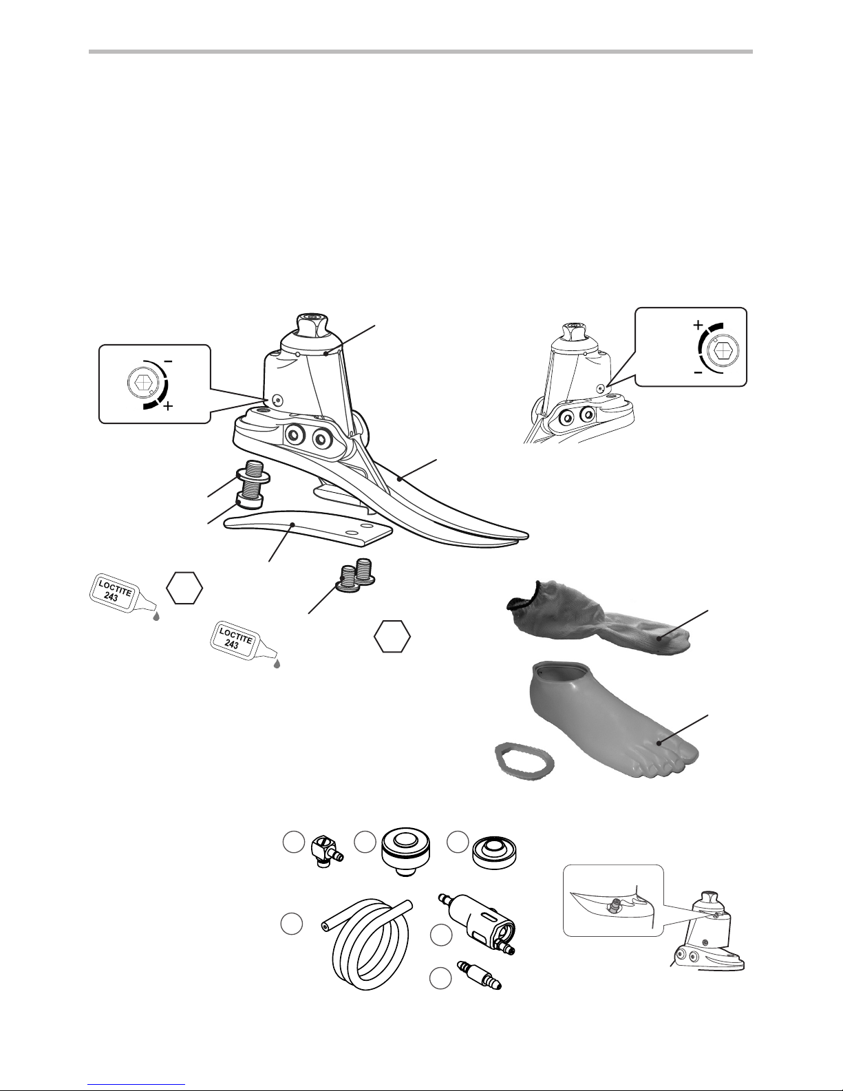
Principal Parts:
• Hydraulic Body Assembly including pyramid (Aluminium/St. Stl./Titanium)
• Carrier Assembly (Aluminium/St. Stl.)
• Heel & Toe Springs (e-Carbon)
• Spring Attachment Screws (Titanium/St.Stl.)
• Glide Sock (UHM PE)
• Foot Shell (PU)
• Vacuum Parts (PU, Nylon, Aluminium)
2 Construction
Glide
Sock
Foot
Shell
Toe
Spring
Min 1
Dorsiexion
Valve Adjuster
(opposite Plantar
Flexion adjuster)
DF
Heel Spring
Screws
(Loctite 243)
Plantar Flexion
Valve Adjuster
Toe Spring
Washer
Toe Spring
Screw
(Loctite 243)
PF
Heel
Spring
4
15Nm
8
35Nm
Attachment
Plate
Min
Max
Min
Max
Carrier, Hydraulic
Body and Vacuum
Assembly
Vacuum System Parts
1 Vac Barb 90deg
2a Auto-Expulsion Valve
2b Threaded Housing
3 Check Valve
4 In-line Filter
5 Vacuum Tubing
Vacuum Connector
1
3
5
2a
4
2b

4
938367/1-0816
3 Function
The EchelonVAC comprises a hydraulic body assembly containing adjustable hydraulic valves.
The valves can be independently adjusted to increase and reduce hydraulic resistance of plantar
exion and dorsiexion.
4 Maintenance
The hydraulic body assembly is connected to a carrier assembly via two pivot pins. Heel and toe
springs are attached to the carrier assembly using titanium and stainless steel screws. The foot is
wrapped in a UHM PE sock which is in turn surrounded by a PU foot shell.
Maintenance must be carried out by competent personnel.
It is recommended that the following maintenance is carried out annually:
• Remove the foot shell and glide sock, check for damage or wear and replace if necessary.
• Check all screws for tightness, clean and reassemble as necessary.
• Visually check the heel and toe springs for signs of delamination or wear and replace if
necessary. Some surface damage may occur after a period of use, this does not aect the
function or strength of the foot.
The wearer should be advised:
Any changes in performance of this device must be reported to the practitioner.
Changes in performance may include:
• Increase in ankle stiness
• Reduced ankle support (free movement)
• Any unusual noise
• Lack of vacuum
Cleaning:
Use a damp cloth and mild soap to clean outside surfaces, do not use aggressive cleansers.
The practitioner must also be informed of:
• Any changes in body weight and/or activity level.
• Discoloration of the residual limb.
The hydraulic body also houses a pneumatic chamber and piston which, via one-way valves
and a lter, creates a vacuum that can be passed via tubing to a prosthetic socket. For maximum
vacuum eect the check valve should be positioned close to the ankle. The number of steps
necessary to create an elevated vacuum will vary depending on the free space/air in the system.
The use of multiple socks may require an increased number of steps to reach an elevated
vacuum.
NB. if high hydraulic resistances are used such that they restrict ankle movement, the ability to
generate vacuum may be compromised.
5
938367/1-0816
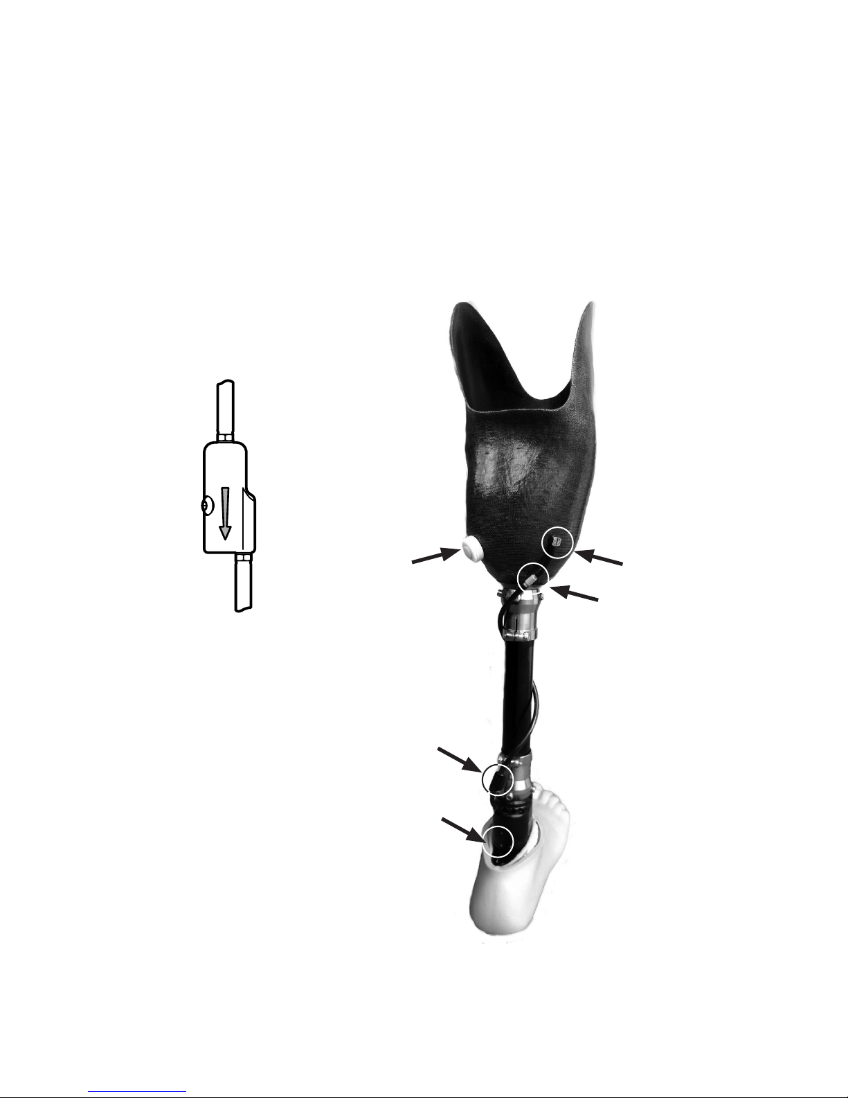
4.1 Vacuum System Maintenance Guide
1 Visual Inspection
Make a visual inspection of the system parts paying attention to connections, these must be air
tight to ensure integrity of the vacuum. Inspect the tubes and ensure they are rmly connected
and are not kinked or split. The socket arrangement should also be inspected to check the
integrity of the vacuum seals.
Auto-Expulsion
Valve In-line Filter
Check Valve
Vac Barb
90deg
distal
tube
2 Check Valve
The check valve retains the vacuum created
in the socket. It must be connected with
the direction arrow pointing towards the
EchelonVAC ankle.
proximal
tube
Connector
6
938367/1-0816
Check the Auto-Expulsion Valve
in the socket
The valve should be silent after the user takes some steps.
Check that the seal is not compromised, clean it or replace
it if required.
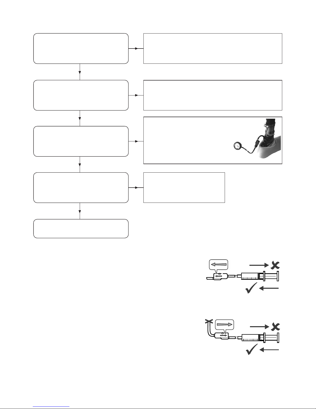
1 Cleaning the Check Valve, vacuum inlet
Disconnect the check valve and connect a syringe to the proximal
tube with the ow direction arrow pointing away from the syringe.
If the valve is working correctly the syringe should only push
inwards. If the valve is blocked use the syringe to clear the valve
with a‘blast of air’ (Do not use compressed air). If it is still blocked
clean it with distilled water using the syringe. If the valve is still not
working replace it (409663 or 409863).
2 Cleaning the Check Valve, exhaust port
Check the exhaust valve is working correctly by connecting a
syringe to the distal tube and clamp the proximal tube. Use a
‘blast of air’ to clear it through (Do not use compressed air). If
the exhaust valve is working correctly and retaining the vacuum
it should not be possible to draw the syringe plunger back out
again.
4.2 Vacuum System Checklist
Inspect the tubing and connections Ensure the tubes are rmly connected and are not
kinked or split, replace if required.
Check that a vacuum is being
created at the ankle using a vacuum
gauge or syringe
Fully plantar ex and dorsiex the
foot several times.
If the vacuum is working and there is
no vacuum at the socket, the In-line
Filter or the Check Valve may need
replacing.
Check the Check Valve See Cleaning the Check Valve
Contact your practitioner or
Endolite representative
7
938367/1-0816
5 Limitations on Use
Intended life:
A local risk assessment should be carried out based upon activity and usage.
Lifting loads:
User weight and activity is governed by the stated limits.
Load carrying by the user should be based on a local risk assessment.
Environment:
Avoid exposing the EchelonVAC to corrosive elements such as water, acids and other liquids. Also
avoid abrasive environments such as those containing sand for example as these may promote
premature wear.
Exclusively for use between -15˚C and 50˚C (5˚F to 122˚F).
It is recommended that only Endolite products be used in conjunction with the EchelonVAC.
For use only by appropriately trained practitioners.
Should only be used with well tting total surface bearing sockets with no reliefs or voids, which
have been constructed with air tight sockets and a suspension sleeve to create an air tight seal
proximally.
8
938367/1-0816
½½
0-10mm
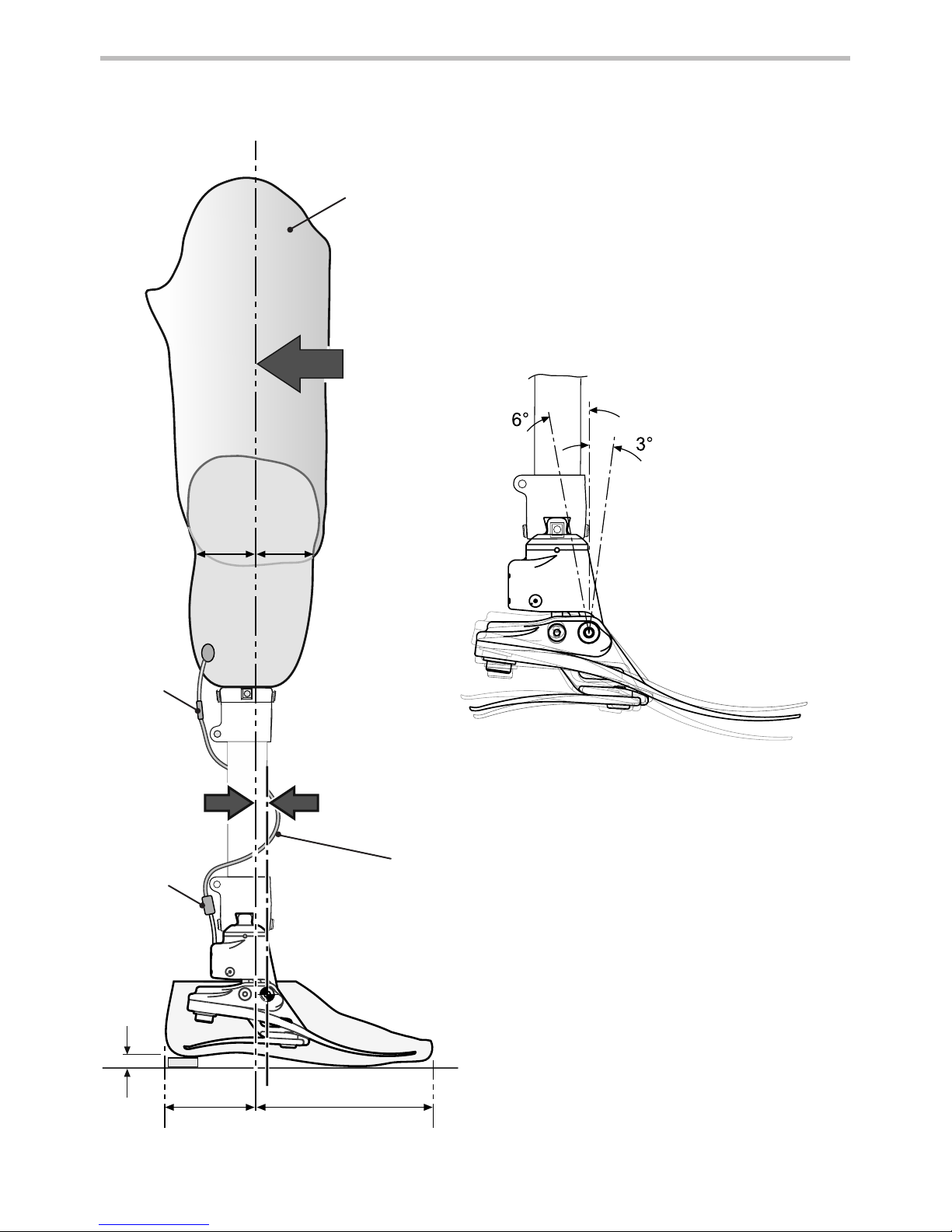
6 Bench Alignment
6.1 Static Alignment
Align limb to
achieve range of
motion shown.
Approx. 1/3 2/3
Build
Line
Allow for users
own footwear
*
Align trans-femoral devices according to tting
instructions supplied with the knee.
Keep the build line between foot pivots as shown,
using shift and/or tilt devices as necessary.
In-Line
Filter
*
For the Vacuum System
Assembly see section 8.0
Wrap the vacuum tubing
around the pylon as shown and
position the Check Valve close
to the ankle for the best vacuum
performance.
Check
Valve
9
938367/1-0816
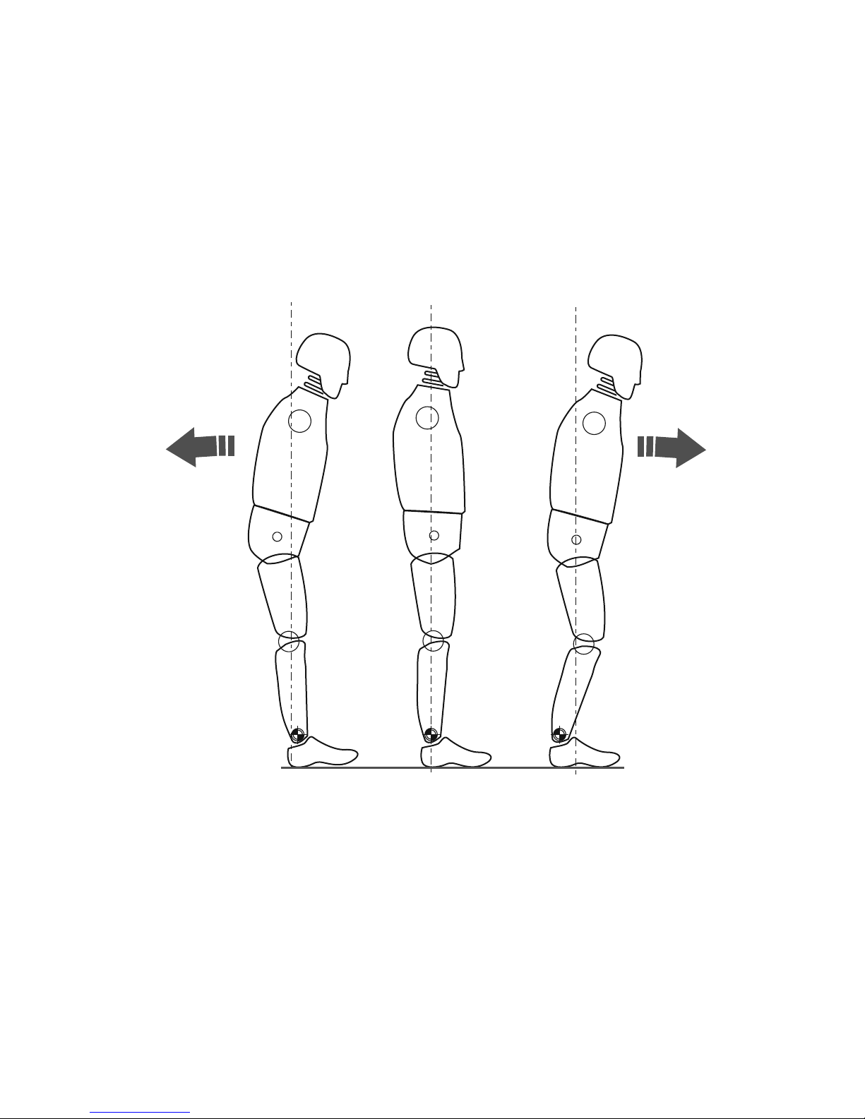
6.2 Biomimetic Alignment
The aim of alignment is to achieve a“balance point” while standing and set the hydraulically
damped range of motion. The aim of damping adjustment is to ne tune the ankle-foot roll-
over stiness characteristics until a comfortable gait is achieved. Due to the increased range of
motion provided by the ankle the user may experience the need for more voluntary control and
initially nd the ankle disconcerting during setup. This should quickly pass upon completion of
satisfactory setup.
Ensure that the user is relaxed and not resting on the dorsiexion limit.
Falling backwards =
[Hyper-extension]
A-P shift too far forward
Falling forwards =
[Hyper-exion]
A-P shift too far back
10
938367/1-0816
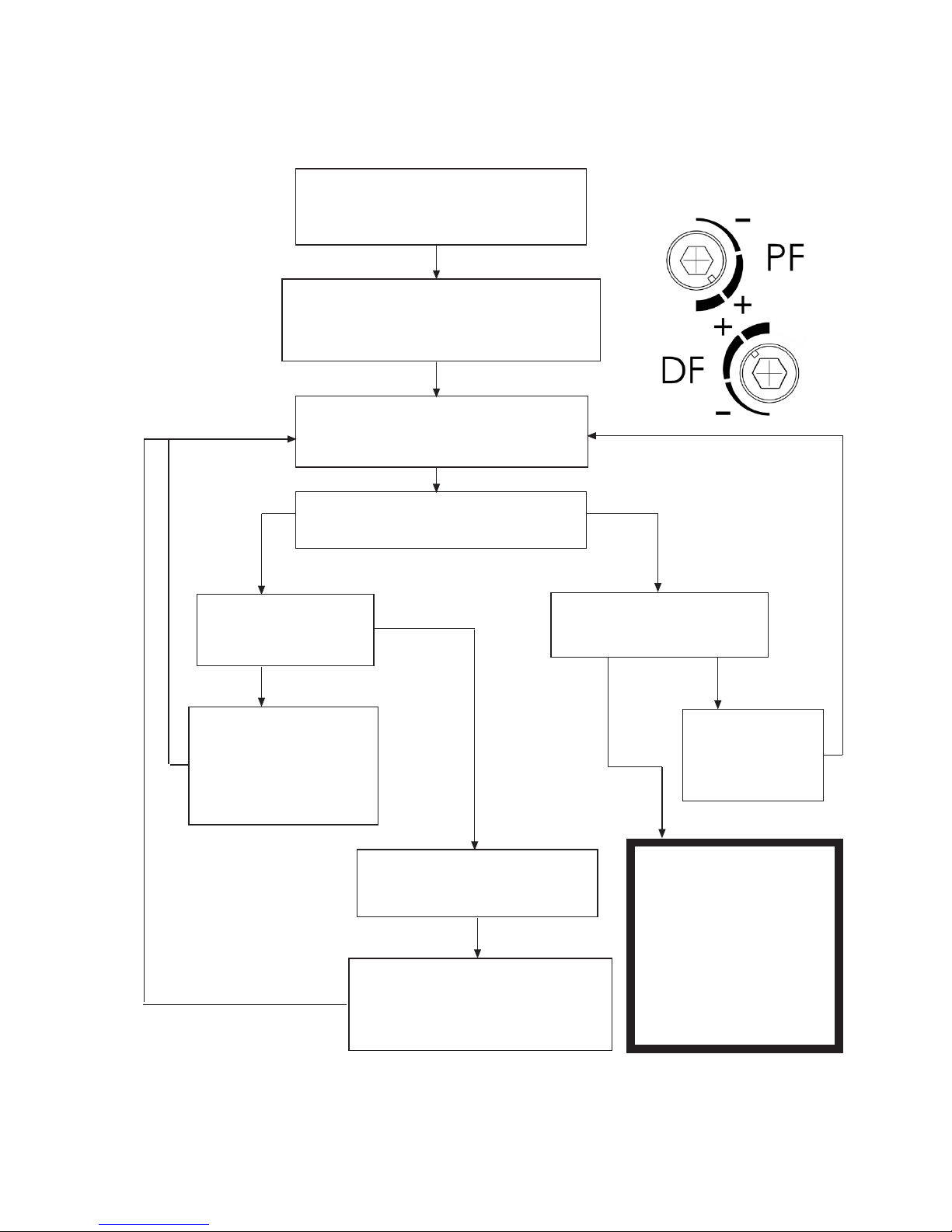
6.3 Biomimetic Adjustment
NB: Carry out static alignment while ensuring the user has some means of support such as
parallel bars. This is standing alignment only.
Check bench alignment taking
heel height into account
Ensure PF and DF valves are set as shown.
(the user must feel some movement in
the ankle)
Ask the user to stand with weight
evenly distributed between each foot
Does the user feel sufficiently stable
using minimal muscle control?
No Yes
Does the user report
a feeling of falling
forwards?
Shift the foot forwards
slightly relative to the
socket (e.g. tilt using
proximal & distal
interfaces)
Yes
No
Yes
Yes
Can the user dorsiflex the
ankle by approx. 3°?
Adjust the angle
of the foot at the
distal pyramid
interface
Does the user report a
feeling of falling backwards?
Shift the foot backwards slightly
relative to the socket (e.g. tilt
using proximal & distal interfaces)
Proceed to
Dynamic
Adjustment
Allow user to become
accustomed to the ankle for
10 mins before carrying
out any DF/PF valve
adjustments
Use shift for static alignment and standing.
The device should encourage some degree of self adjustment to achieve a sense of balance for
the user during standing.
No
}
11
938367/1-0816
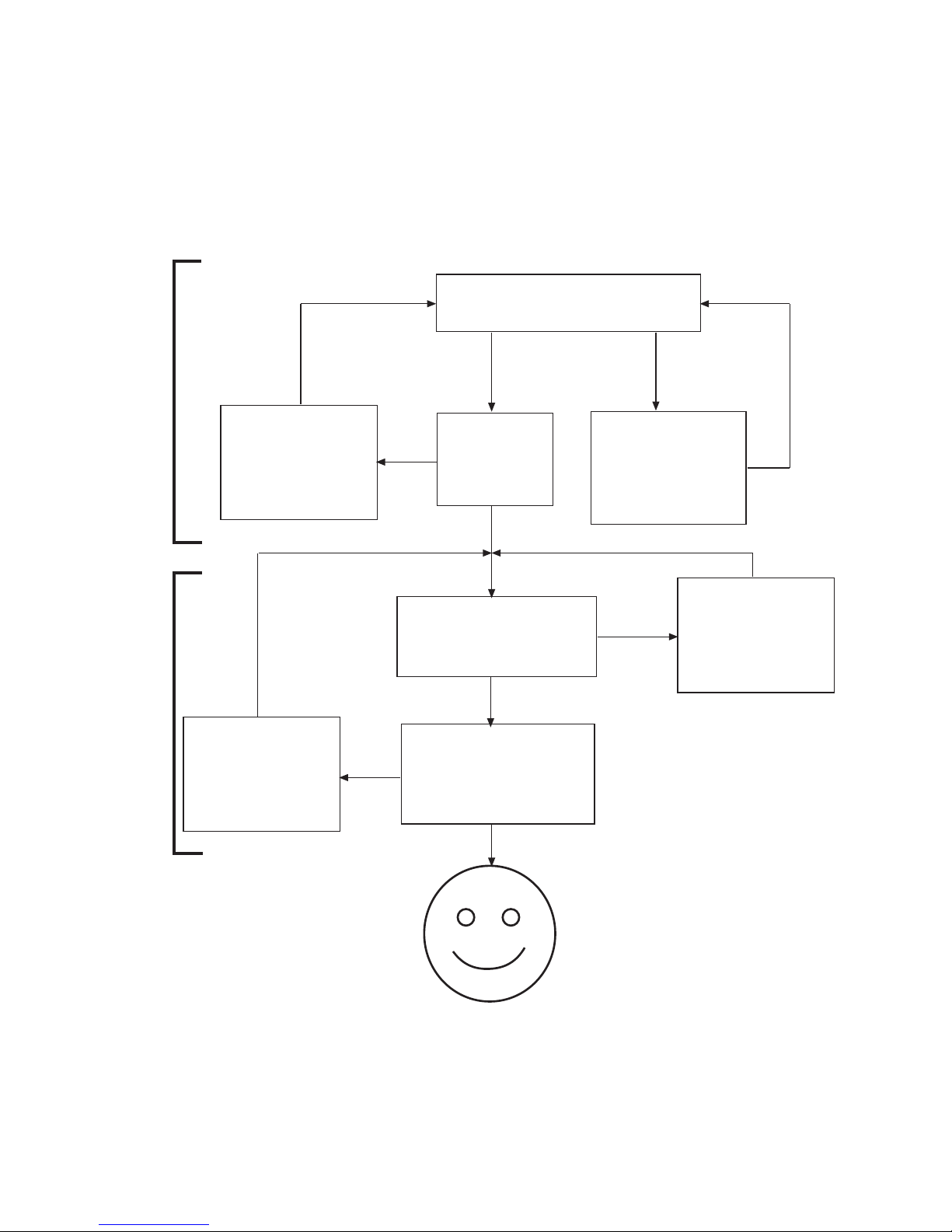
Upon walking, does the user
experience foot slap?
No Yes
Adjust the Plantar
flexion valve to
reduce resistance
(counterclockwise)
No
Yes
Yes
Yes
No
No
Adjust the Plantar
Flexion valve to
increase resistance
(clockwise)
Adjust the
Dorsiflexion
valve to
reduce resistance
(counterclockwise)
Does the
user find the
heel too
hard?
Transfer should be smooth.
Does the user feel as if they
are walking uphill?
Does the user feel as
if they are being
thrown forwards
through stance?
Adjust the
Dorsiflexion
valve to
increase resistance
(clockwise)
PF
1st
6.4 Dynamic Adjustment
Adjustment of the hydraulic valves.
The user should experience the ankle moving smoothly with the body through the gait cycle
with no additional eort required by the user to overcome the hydraulic resistance of the ankle.
During this procedure the user should walk at normal speed, in a straight line on a level surface.
Guidance:
Following dynamic adjustment, trial the foot/ankle on ramps and stairs. Ensure the user is
comfortable with the kind of terrain he/she may normally be expected to encounter. If the user
reports any issues with comfort, usability or range of movement of the ankle, adjust accordingly.
DF
2nd

12
938367/1-0816
7 Fitting Advice
The springs for the EchelonVAC foot will be supplied assembled with heel and toe springs of the
same category. If after following the instructions below you still have problems with the function
please contact the sales team in your area for advice.
Any of the following:
• Incorrect spring selection
• Incorrect A-P shift alignment
• Incorrect distribution of plantar exion and dorsiexion range
will have a negative eect on function and stability.
Symptoms: Remedy
1. Sinking at heel strike
Diculty in achieving a smooth
progression to mid stance
User feels they are walking up hill
or forefoot feels excessively long
1. Increase plantar exion resistance
2. Check A-P shift alignment; ensure foot is not too
anteriorly positioned
3. Check distribution of plantar exion and
dorsiexion movement; ensure that the plantar
exion range is not excessive
4. Check spring category is not too soft,
if so t a higher rate spring
2. Progression from heel strike to mid
stance is too rapid
Diculty in controlling the energy
return from the foot at the heel
strike (reduced knee stability)
User feels heel is too hard, fore foot
is too short
1. Reduce plantar exion resistance
2. Check A-P shift alignment; ensure foot is not too
posteriorly positioned
3. Check distribution of plantar exion and
dorsiexion movement; ensure that there is
adequate plantarexion range
4. Check the spring category is not too high for the
weight and activity of the patient, if so t lower
rate spring
3. Heel contact and progression feel
OK but:
Forefoot feels too soft
Forefoot feels too short
User feels they are walking down
hill, possibly with reduced knee
stability
Lack of energy return
1. Increase dorsiexion resistance
2. Check A-P shift alignment;
ensure foot is not too posteriorly positioned
3. Check distribution of plantar exion and
dorsiexion movement; ensure that there is not
excessive dorsiexion range
4. Check the spring category is not too soft for the
weight and activity of the patient, if so t higher
rate spring
The correct alignment (A-P position), range of motion (distribution of plantar exion to
dorsiexion) and adjustment of the hydraulic settings are critical in achieving a smooth roll over
and correct slope adaptation (see 6.3).
The user should feel the vacuum eect after taking approximately 15-20 steps depending on the
initial socket t.
13
938367/1-0816
Symptoms: Remedy
4. Forefoot feels too rigid
Forefoot feels too long
Feels like walking up hill
1. Reduce dorsiexion resistance
2. Check A-P shift alignment;
ensure foot is not too anteriorly positioned
3. Check distribution of plantar exion and
dorsiexion movement; ensure that there is
sucient dorsiexion range
4. Check the spring category is not too rigid for the
weight and activity of the user, if so t a lower
rate spring
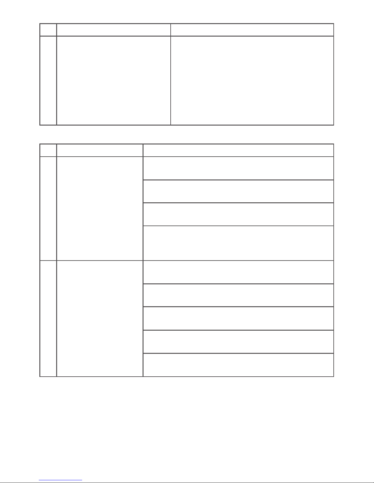
Symptoms: Cause/Remedy
1. Unable to generate a
vacuum
Vacuum tube(s) split or disconnected
Inspect and repair/replace as necessary
Check and clean/replace the check valve
Filter blocked, replace Filter
Limited ankle movement creating insucient vacuum due to:
1. Excessive PF/DF setting
2. Footwear
2. Unable to maintain a
vacuum
Vacuum tube(s) split or disconnected
Inspect and repair/replace as necessary
Check and clean/replace the check valve
Leakage at socket valve/barbs
Reseal valve/barb
Porous socket
Seal with lacquer/re-make
Check the integrity of the vacuum seal at the socket/
residuum interface
Vacuum System
2
3
1
4
5 6
14
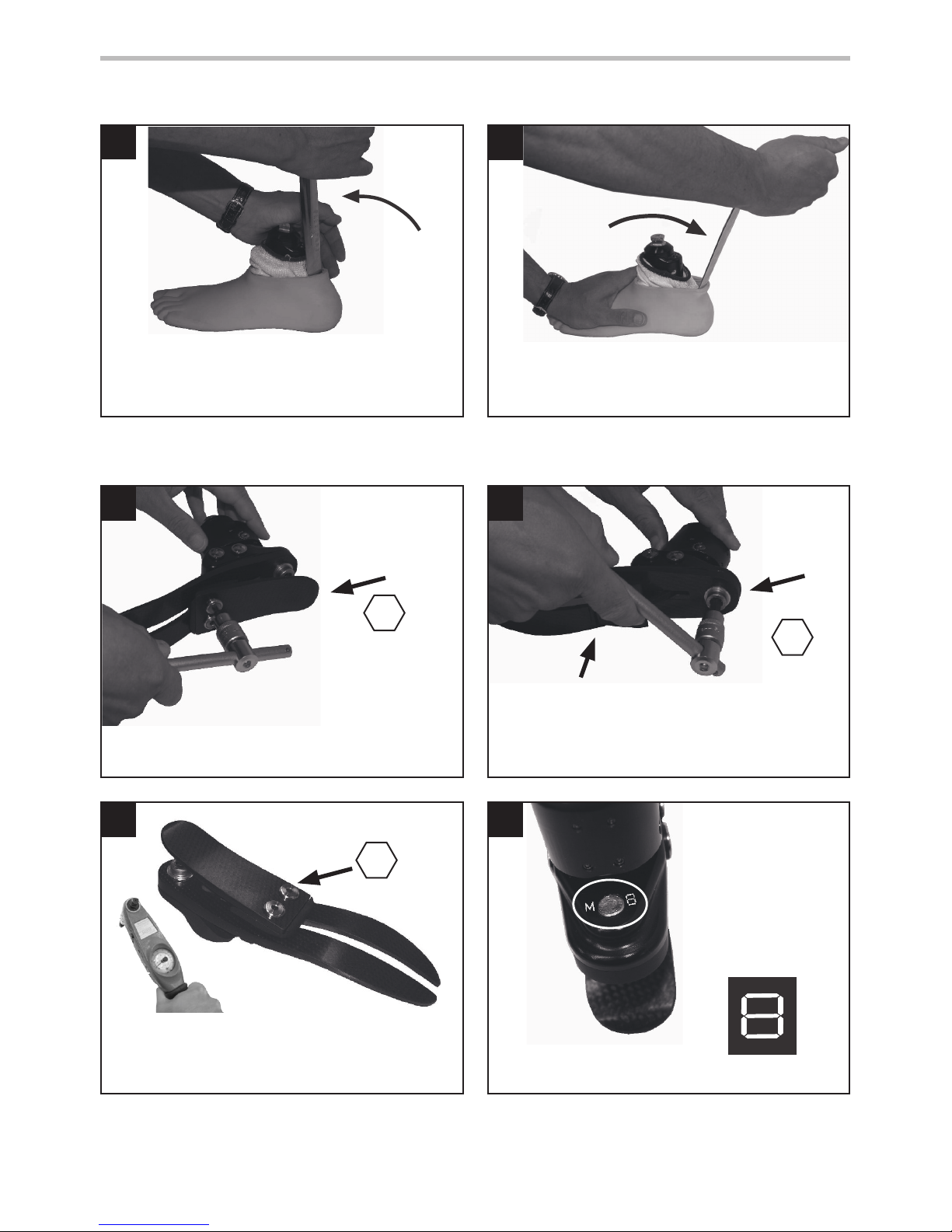
938367/1-0816
Insert shoe horn behind Heel Spring
Carrier
Assembly
Rotate shoe horn as shown to remove shell
heel Spring
Re-assemble with replacement heel spring. Use
Loctite 243 (926012) and torque to 15Nm.
Cover appropriate
lines on the carrier
with permanent
black marker to
leave the spring set
number showing.
Remove Heel Spring and screws.
Remove toe spring screw, replace toe. Upon
reassembly, use Loctite 243 (926012) and torque
to 35Nm. Ensure toe spring is central to the
carrier.
35Nm
4
8
4
15Nm
Spring Replacement
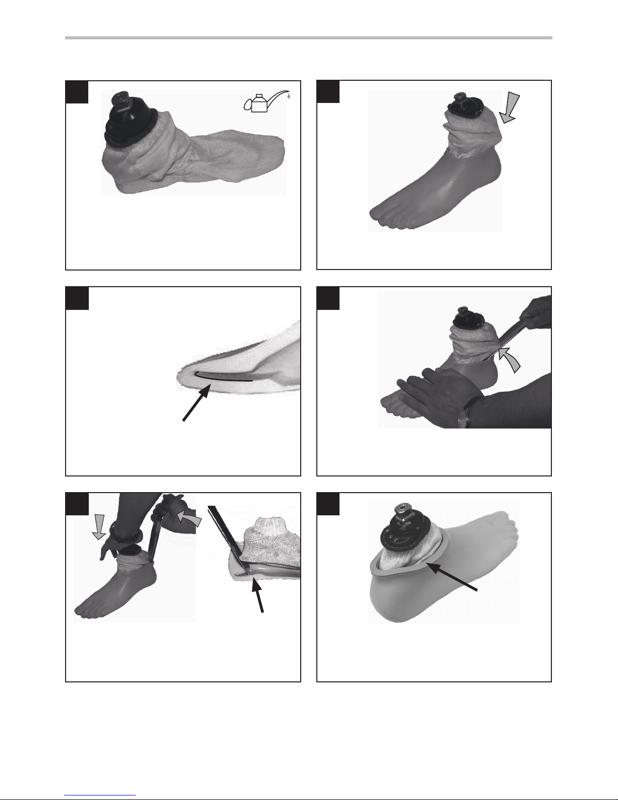
8 Assembly Instructions: Footshell Removal
Toe Spring
8
10
12
9
7
11
15
938367/1-0816
If a cosmetic nish is required please contact a member of the Endolite Sales Team.
Lubricate toe and heel if required.
(Footshell is pre-lubricated).
928017
Slide carrier/Heel Spring Assembly into the Foot
Shell.
toe spring location in Foot Shell Use a suitable lever to encourage the Heel Spring
into location in the Foot Shell.
Press Heel Spring into location in shell as shown.
Heel Spring
location slot
Ensure Glide Sock does not get trapped when
assembling to female pyramid part.
Cosmetic
Attachment
Plate
Fit Sock as shown.
Assembly Instructions continued
16
938367/1-0816
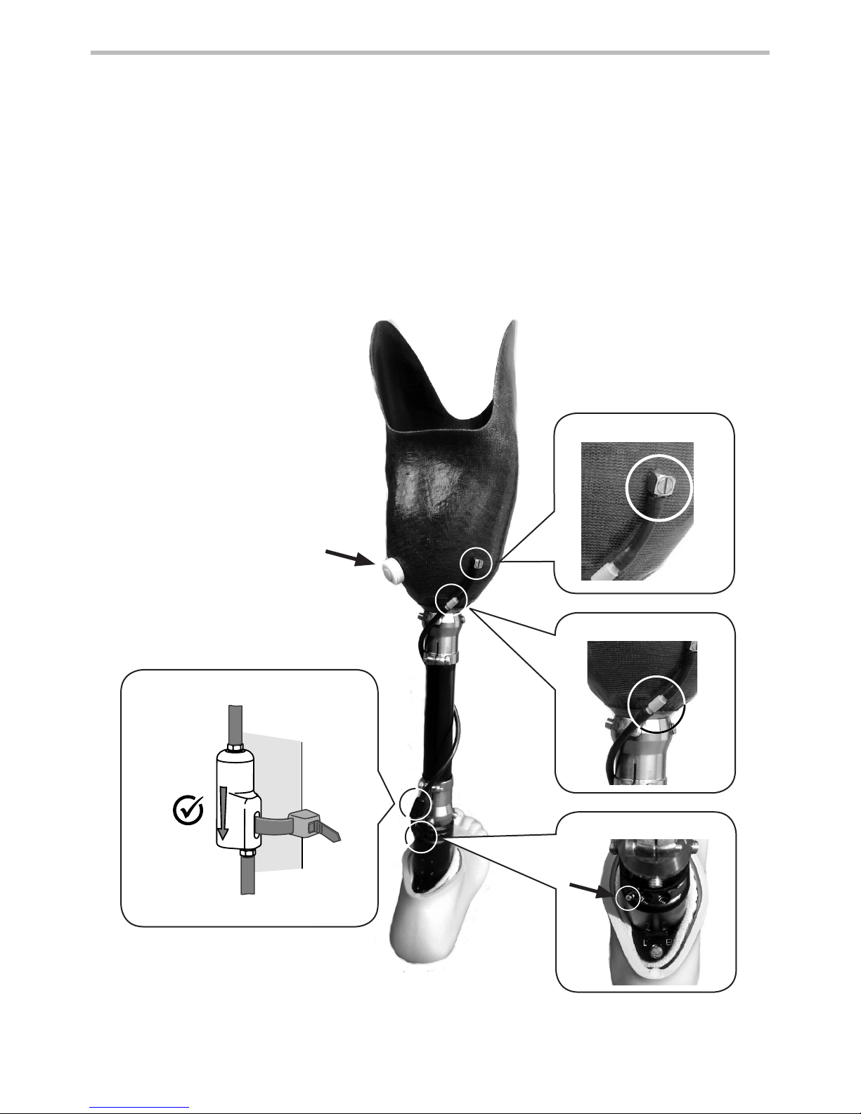
Vacuum System Assembly
1 Push the In-line Filter on to a short piece of vacuum tubing and connect it to the Vac Barb
90deg on the socket. The barb outlet should be positioned pointing downwards by releasing
the centre screw and rotating the body of the unit. Tighten the screw when the barb outlet is in
the required position.
2 Attach a length of vacuum tubing to the In-line Filter and wrap it around the pylon. Connect
the other end of the tube to the Check Valve ensuring that the ow arrow points towards the
ankle. For maximum vacuum, position the Check Valve close to the inlet on the EchelonVAC.
Connect a short length of vacuum tubing from the Check Valve to the inlet on the ankle to
complete the vacuum system.
Auto-Expulsion
Valve
In-line Filter
Inlet
Vac Barb 90deg
Assembly Instructions: Vacuum System
Check Valve
17
938367/1-0816
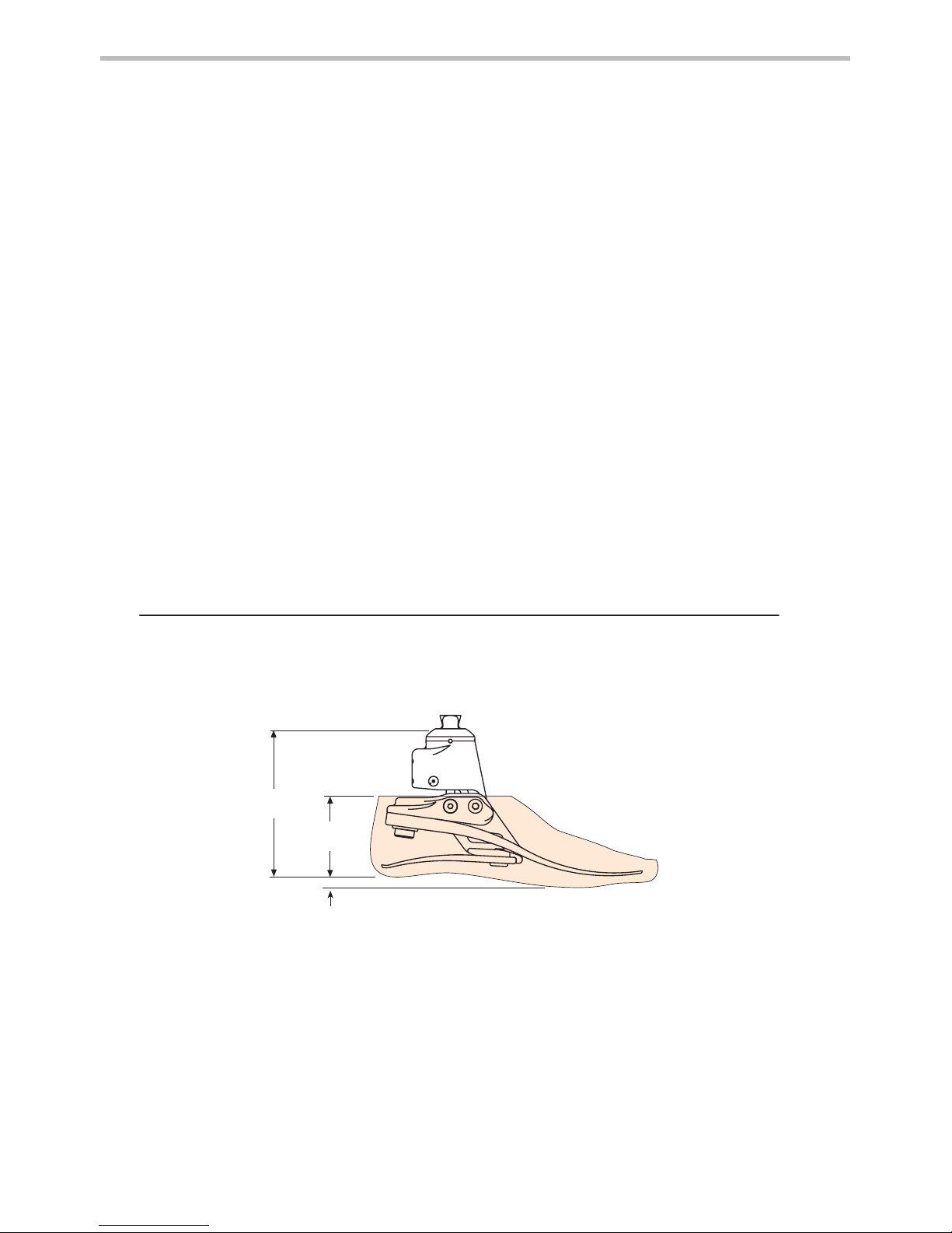
* sizes
22 - 24 = 121mm
25 - 26 = 126mm
27 - 30 = 131mm
** sizes
22 - 24 = 70mm
25 - 30 = 75mm
Fitting length
9 Technical Data
Operating and
Storage Temperature Range: -15˚C to 50˚C
(5˚F to 122˚F)
Component Weight [size 26]: 930g (2lb 1oz)
Recommended Activity Level: 2, 3, 4
Maximum User Weight: 125kg (275lb)
Proximal Alignment Attachment: Male Pyramid (Endolite)
Range of Hydraulic Ankle Motion:
(excludes additional range of motion
provided by heel and toe springs)
6 degrees plantar flexion
to 3 degrees dorsiexion
Build Height:
[See diagram below]
[sizes 22-24] 120mm
[sizes 25-26] 125mm
[sizes 27-30] 130mm
Heel Height: 10mm
Maximum Vacuum: 17in Hg
10mm
***

18
938367/1-0816
10 Ordering Information
Cosmetic interface (for dark add‘D’)
22-24L&R 530138 25-26 L&R 531035
27L&R 531935 28 L&R 531936
29L 532831 29R 532832
30L 532833 30R 532834
Glide Sock
One size ts all Part No. 532811
DF/PF Adjuster Key
4.0 A/F Allen Part No. 940236
Spring Kits
Rate
Foot sizes
22-24 25-26 27-28 29-30
Set 1 539801 539810 539819 539828
Set 2 539802 539811 539820 539829
Set 3 539803 539812 539821 539830
Set 4 539804 539813 539822 539831
Set 5 539805 539814 539823 539832
Set 6 539806 539815 539824 539833
Set 7 539807 539816 539825 539834
Set 8 539808 539817 539826 539835
Foot shell (for dark add‘D’)
Small Medium Large Extra Large
22L 539038 25L 539044 27L 539048 29L 539052
22R 539039 25R 539045 27R 539049 29R 539053
23L 539040 26L 539046 28L 539050 30L 539054
23R 539041 26R 539047 28R 539051 30R 539055
24L 539042 -- -- --
24R 539043 -- -- --
Vacuum System Parts:
Socket Connection Kit Part No. 409663
Check Valve
Service Kit Part No. 409863
Table of contents
Languages:
Other endolite Medical Equipment manuals

endolite
endolite Smart IP System SMARTIPSFPYR User manual

endolite
endolite Navigator Foot User manual

endolite
endolite aqualimb TF User manual

endolite
endolite Smart IP User manual

endolite
endolite Echelon User manual

endolite
endolite BladeXT User manual

endolite
endolite Comfort Cushion Liner CTTCP22L User manual

endolite
endolite linx User manual

endolite
endolite AvalonK2 User manual

endolite
endolite AqualimbTT User manual


