enorossi ENOSPE US User manual
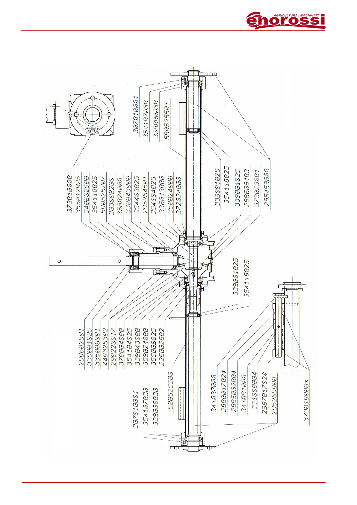
ENOAGRICOLA ROSSI s.r.l.
Via Cortonese s.n
Calzolaro di Umbertide 06018 Pg Italia
Tel. (39) 075-930 22 22 - Telefax (39) 075-930 23 28
EC DECLARATION OF CONFORMITY
(Annex IIA - Machinery Directives 2006/42/EC)
The Manufacturer ENOAGRICOLA ROSSI s.r.l.
with head office in via Cortonese s.n. - 06018
Calzolaro di Umbertide (PG) - Italy
it declares under its own responsibility
that the machine
whose functions are described in this manual
is conform to the Essential Requirements of Safety and Health Protection, as per
Machinery Directive 2006/42/EC and to the Directive 94/20/EC relating to the mechanical coupling
devices of motor vehicles and their trailers and their attachment to those vehicles
To check the conformity of the Directives mentioned up here, the following
EN Harmonized Norms have been consulted:
UNI EN ISO 3767-2 (1998) - EN ISO 4254-1 (2008) - EN 4254-8 (2009) - EN 4413 (2010)
ISO 11684 (1995) - EN 12100:2010 -EN 12965:2010 -EN 14017:2010 - UNI EN ISO 13857:2008
and it authorizes Giovannini Massimo
Via Cortonese s.n. - 06018
Calzolaro di Umbertide (PG) - Italy
to compile the relevant technical documentation
GIOVANNINI ADELMO
Calzolaro di Umbertide, …….. ……. …… ….……………………….
Legal representative
PULL TYPE FERTILIZER SPREADER
……………………………………………………………………………………….…………………………………..
Generic denomination and commercial name
ENOSPE US
…………………………..
Series/Model
….
……………………………………………
Serial number
20..
…………….
Manufacturing year

3
CONTENTS
EC DECLARATION OF CONFORMITY
2
GENERAL SAFETY REGULATIONS
4
SAFETY DECALS
5
SAFETY RULES AND PREVENTION OF ACCIDENTS
6
EQUIPMENT ASSEMBLY
7
REGULATING OF THE FERTILIZER SPREADER
14
SERIAL NUMBER AND IDENTIFICATION PLATE
15
MAINTENANCE
16
SERVICING
16
SPARE PARTS
18
SPREADING CHART FOR FERTILIZER
22
SPREADING CHART FOR SEEDS
23

4
General Safety Regulations
In addition to the safety regulations given in this manual it is imperative that the general rules
for safety and hygiene at work be respected at all times, as well as the public highway code.
-Before commencing work with the machine it is necessary to become familiar with the
operation of the controls and operating devices.
-Before switching on the tractor make sure that all the protection elements are correctly
assembled.
-Do not handle the machine when the power take-up is rotating.
-Do not exceed the maximum load capacity of fertilizer recommended by the Manufacturer.
-Do not use any equipment not recommended by the manufacturer, and do not modify the
machine or its components.
-Before leaving the tractor make sure the spreader is lowered to the ground and switch off
the tractor.
Read this manual carefully before operating the equipment.

5
Safety Decals
Adhesives and plates with symbols on them are applied on the equipment. These safety
symbols are to assist the operator in order to avoid possible risks of accidents during working,
servicing and storage.
This manual will explain the following symbols:
Symbol
Description
Use protection gloves
Use safety eye glasses
The following symbols are attached to the equipment:
Symbol
Description
Consult the operator and servicing manual
Do not pass or stand near the equipment while in use
Danger for hands and/or feet

6
Safety rules and prevention of accidents
The operator of this fertilizer spreader must be competent and being good physical and visual
conditions and must be able to co-ordinate the different functions. Moreover he must apply the
established rules and act with the necessary precaution while carrying out a job, so that he does
not expose himself or other people to danger.
The operator must put the indications given in this manual into practice and he has also to make
possible third persons to assume their responsibilities.
The operator must act only after being certain and sure on how to use the entire equipment. He
must not neglect the servicing of the machine.
During the job, the operator must be able to control the machine and oversee the area where
the machine is operating.
It is compulsory to wear working garments which are not too wide, preferably overalls, which
have no loose parts that can get entangled in parts of the machine.
Do not work without sufficient lighting in the working area.
Do not make any emergency repairs on the machine in order to start or finish a job.
Check that the instruction/warning plates and adhesives are clean and easily seen and that the
safety devices are in place and well locked.
Do not drink alcohol or take medicines before or during work or when carrying out
maintenance/service work.
Always use gloves and if necessary safety eye glasses during servicing of the fertilizer machine.
Do not clean or oil parts of the fertilizer machine while in motion/use.
Check the conditions of the bolts and tighten them adequately before starting work.
Check if there are foreign objects in the hopper and be careful not to drop the bag, which
contains the fertilizer, into the hopper.
Do not carry objects that could slip out of your pockets or your breast-pockets while leaning over
the machine.
The operator must never leave the driving place before:
1. disengaging the power-take-off shaft
2. lowering the fertilizer spreader to the ground
3. turning off the tractor engine
4. inserting the parking brake and low gear
5. taking the ignition key out of the control board
All the necessary interventions must be carried out when the fertilizer spreader machine is
switched off.

7
US Assembly
Assemble the gearbox (2) to the frame (1), by means of screws (3) and nuts (4) and tighten
them.
Now insert the disc (5) on the gearbox (2) and fix it by means of pin (6) on the hole placed
under the disc. Fix the fans (7) to the disc (5) by means of proper bolts (8) and nuts (9).
Assemble the beam (10) by means of the screw (11) and the self-locking nut (12). After this,
assemble the holder linkage (18) by means of the relevant bolts (19) and nuts (20). If you have
bought a machine with a caravan hitch, take the linkage (21), assemble it on item (18) by means

8
of bolts (22) and nuts (23). Mount the standing (24) and stop it by adding the copper pin (25).
So take the two connecting rods (13) and fix by means of bolts (14) (15) and nuts (16) (17).

9
Next, assemble the disengaging lever (26) by means of the screw (27), the washer (28) and the
self-locking nut (29) paying attention to keep loose the self-locking nut.
Connect the rubber handle (30) and the chain (31) by means of proper screw (32), nut (33) and
“R” cotter pin (34).

10
Fix the guard (35) to the machine by inserting the screws (36), the washers (37) and the nuts
(38).
Connect the Right H. lever (39) and the Left H. one (40) to the frame by means of proper screw
(41), insert the spring (42) in the screw and tighten the self- locking nut (43), then insert the
rubber handles (30).Fix the two levels (39) (40) by means of screws (68) and nut (69).

11
Take the hopper (44), insert the bushing (45), with the Left H. shutter (46) and the Right H. one
(47), fix everything by means of seeger (48).
Set the hopper (44) on the frame (1) and fix by means of bolts (49) and nuts (50).
Put the agitator (51) into the gearbox shaft (2) and fix by means of the screw (52) and the self-
locking nut (53).

12
Assemble the short opening connecting rod (54) and the long one (55), then put the short
connecting rod into the return (56) and tighten the self-locking nut (57). Next stop the
connecting rods trough the split pins (58).
Place the brushes (59) in the upper side of disengagement box (60); next connect the lower
disengagement box (61) and the upper one to the machine by tightening screws (62) and self-
locking nuts (63).

13
Fix the guard (64) by means of bolts (65) and nuts (66); mount the arms (67) by fitting bolts (68)
and nuts (69) while on the other side fix the guard to one of the screws which support the
hopper.
Finally, assemble the wheels (70) by means of screws (71) and self-locking nuts (72).

14
Regulating of the fertilizer spreader
As suggested in figure C, to obtain the maximum fertilize and
seed spreading, bring the lever 1 and 2 to position of
maximum opening. Above mentioned levers can be fixed by
a screw.
To spread to the left (of the forward direction) remove the link
screw and bring the lever no. 1 to the maximum opening
while no. 2 must be in the position “0” (figure D).
To spread to the right (of the forward direction) the lever no.
1 must stand at the position “0” and no. 2 at the maximum
opening.
For a larger spreading distance you can act on fixed wings of the disc:
-Slacken the bolt positioned near the centre of the disc;
-Remove the external bolt which fixes the wing;
-Move the wing toward the more correct position;
-Reassemble the bolt screwing down it well;
-Tighten the other fixing bolt.
The same operation must be repeated with the other three wings,
remember to maintain the same order for all of them

15
Tel. +39 075.9302222 - Fax +39 075.9302328
YEAR Kg
SERIAL NUMBER kW
ENOAGRICOLA ROSSI s.r.l.
CALZOLARO DI UMBERTIDE - PERUGIA - ITALIA
MODEL
Serial number and identification plate
Manufacturer: ENOAGRICOLA ROSSI s.r.l. via Cortonese s.n. –06018 Calzolaro di Umbertide
(PG) - Italy
-Equipment: Pull type Fertilizer Spreader
-Manufacturing year
-Weight
-Model
-Serial number
-Tractor power
PULL TYPE FERTLIZER SPREADER

16
Maintenance
The servicing of your spreader is very important and must be done carefully as it gives a lower
operational cost and a long life of the equipment.
Servicing
In this part of the manual we examine the most frequent cases of servicing:
After use
-wash the machine with water;
-dry all the metal parts carefully;
-grease all the moving parts of the machine;
-check and tighten all bolts.
Periodical servicing
-change the oil and grease in the gear box after the first 30 working hours;
-every subsequent 250 hours of work this operation has to be repeated by unscrewing
the drainage cap of the gear box and waiting for the oil to drain out completely;
-turn the machine in such a way as to have the cap opening in the ideal position to fill up
the gear box with about 0,25 kg of new oil;
-check the metal parts which are under great strain during working conditions and if
necessary replace them.
Replacement servicing
-wash the machine with water and sodium carbonate, taking care to dry the machine
properly;
-retouch the metal parts with paint if necessary lubricate the moving parts with grease and
spray other parts with oil;
-protect the machine by covering it with a nylon or canvas cover stow, in a dry room and
off the ground.

17

18
US GEARBOX

19
US GEARBOX GLOSSARY
CODE
DESCRIPTION
QTY
226002602
DISENGAGING SLEEVE 22x19 DIN 5482
1
290220017
"FAZA" SPREADER BOX 2018 - G25
1
295264601
SHAFT XY 2018 "R" 22X19 DIN 5482 SPEC.
1
295269800
SHAFT WITH FLANGE L=459.5 2018 FAZA
1
295459800
SHAFT WITH FLANGE L=186 2018 FAZA
1
298001702
DISENGAGEMENT LEVER L=70 2018 FAZA
1
298503200
FIXING DISENGAGING ROD COMPASS 2018
1
298602501
PROTECTION D.25X65X9.5
1
298609403
COVER D.94 WITH HOLE 3/8" GAS X 2018
1
298701702
DISENGAGING ROD 2018 D.18 INOX
1
299000400
GREASE NLGI 0-EP
0,01
303008200
SCREWS M 8X25X1,25 C 8,8 UNI5931
12
307010001
SREWS M 10X12X1.5 C12,9 UNI5925 P.CIL
2
336008001
WASHER SCHNORR S8
12
338043000
FLEXIBLE RING .I. 52X2,00 DIN472/1
3
339000030
FLEXIBLE RING . E. 30X2,00 DIN 471/2
2
339001025
FLEXIBLE RING . E. 25X2,00 DIN 471/2
5
340E02500
RINGS - THICKNESS .E.025
1
341037000
FLEXIBLE PIN 8X40 DIN1481
1
341091000
FLEXIBLE PIN 6X28 DIN1481
1
351000004
SPRING D.3 SPREADER DISENGAGEMENT
1
354104025
BEARING 6205 25X52X15 SF
2
354107030
BEARING 6006 2RS1 30X55X13 SF
2
354110025
BEARING 6205 2RS1 25X52X15 SF
1
354116025
BEARING 61905 RS1 25X42X9 SF. Q.I.
2
354403025
BEARING 30205 25X52X16,25 R.C.D.Q.
1
355009025
STABILITY RING 025X042X006
1
355012025
STABILITY RING 025X052X007
1
358024000
RING OR 3181 D. 45,69X2,62
3
370004000
TONGUE B 8X7X18 UNI 6604
1
372024000
LOCK CAP 42X7
1
373010000
PLUG 3/8"GAS CON. DIN906
1
373023001
PLUG 3/8"GAS CIL.+ ALUMINIUM SEAL
1
379018000
BUSHING D. 018X020 L=20 INAPAP1820P10
2
448325302
BEVEL TORQUE R=3,25X2018 SPREADER
1
580525207
COMPL. EXTEN. PIPE L=90 "Z" AXLE
1
580525500
COMPL. EXTEN. PIPE L=478.5 2018 DISENGAG
1
580525501
COMPL. EXTEN. PIPE L=478.5 2018 FAZA
1

20
US
Table of contents
Other enorossi Farm Equipment manuals

enorossi
enorossi G4V-3P User manual

enorossi
enorossi ENODUO TRACER 780 User manual

enorossi
enorossi RR 400 EVO Series User manual

enorossi
enorossi EASY RAKE Series Operating instructions

enorossi
enorossi RR 420 EVO User manual

enorossi
enorossi RT7 User manual

enorossi
enorossi RAKE CADDY Series Operating instructions

enorossi
enorossi G2 Series User manual

enorossi
enorossi EASY RAKE 10 User manual

enorossi
enorossi MAXIMUS 12 User manual