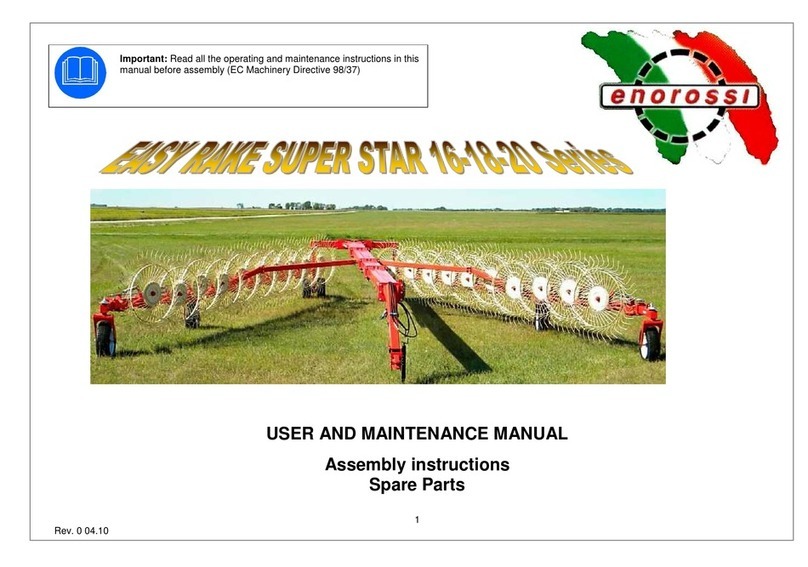
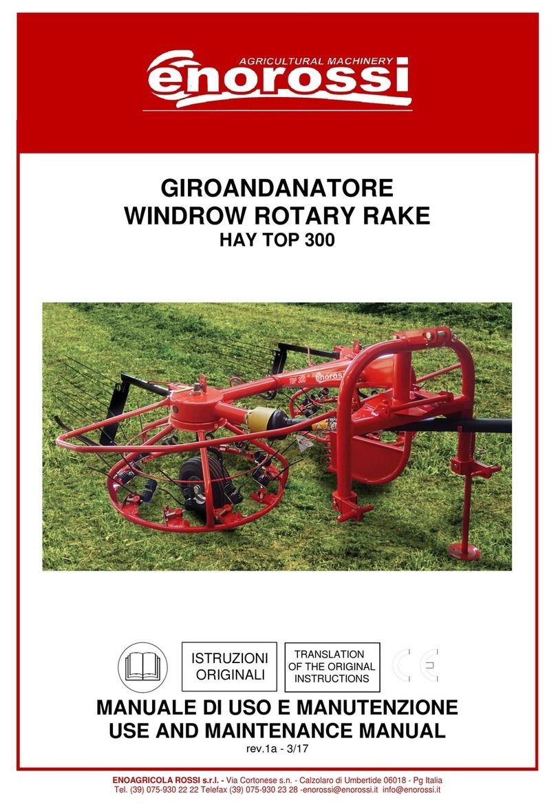
enorossi DR 420 4R User manual

ENOAGRICOLA ROSSI s.r.l.
Via Cortonese s.n
Calzolaro di Umbertide 06019 Pg Italia
Tel. (39) 075-930 22 22 - Telefax (39) 075-930 23 28
DICHIARAZIONE CE
DI CONFORMITÀ
(All.IIA Direttiva Macchine 2006/42/CE)
EC DECLARATION OF
CONFORMITY
(Annex IIA Machinery Directives 2006/42/EC)
Il Fabbricante ENOAGRICOLA ROSSI s.r.l.
con sede in via Cortonese s.n. - 06019
Calzolaro di Umbertide (PG) - Italia
dichiara sotto la propria responsabilità
che la macchina
The Manufacturer, ENOAGRICOLA ROSSI s.r.l.
with head office in Via Cortonese s.n. - 06019
Calzolaro di Umbertide (PG) - Italy
declares under its own responsability
that the machine
le cui funzioni sono descritte in questo manuale
è conforme ai requisiti essenziali di Sicurezza e di Tutela
della Salute di cui alla Direttiva Macchine 2006/42/CE
Per la verifica della Conformità di cui alle Direttive
sopra menzionate, sono state consultate le seguenti
Norme Armonizzate EN:
whose functions are described in this manual
Is conform tothe essential Requirements of Safety and Health
Protection, as per Machinery Directive 2006/42/EC
To verify the conformity of the above-mentioned Directives,
the following EN Harmonized Standarts have been
consulted:
EN ISO 4254-1:2013 - EN ISO 4254-10:2010
EN ISO 4413:2010 - ISO 11684 (1995) - EN 12100:2010
EN ISO 12965:2010 - EN ISO 13857 (2008) - ISO 3600:2015
E autorizza Enorossi
Via Cortonese s.n. - 06019
Calzolaro di Umbertide (PG) - Italia
a costituire il Fascicolo Tecnico per suo conto
and authorizes Enorossi
Via Cortonese s.n. - 06019
Calzolaro di Umbertide (PG) - Italy
To compose the technical documentation on its behalf
GIOVANNINI ADELMO
Calzolaro di Umbertide, …….. ……. …… ….……………………….
Legale rappresentante –Legal Representative
ENOAGRICOLA ROSSI s.r.l.
06019 Calzolaro di Umbertide Perugia Italia
Tel. (39) 075-9302222 - Telefax (39) 075-9302328
www.enorossi.it - www.enoagricolarossi.com
GIROANDANATORE –WINDROW ROTARY RAKE
……………………………………………………………………………………….…………………………………..
Denominazione generica e commerciale –Generis denomination and commercial name
DR 420 4R
…………………………..
Serie/Modello –Series/Model
….
……………………………………………
Matricola- Serial number
20..
…………….
Anno costruz.- Manuf. year

3
INDICE - CONTENT
DICHIARAZIONE CE DI CONFORMITÀ
2
EC DECLARATION OF CONFIRMITY
2
INTRODUZIONE
5
INTRODUCTION
5
INFORMAZIONI SUL MANUALE
5
INFORMATION ON THE MANUAL
5
IDENTIFICAZIONE E CERTIFICAZIONI CE
6
IDENTIFICATION AND EC CERTIFICATION
6
COMPONENTI PRINCIPALI E DATI TECNICI
7
MAIN COMPONENTS AND TECHNICAL DATA
7
GARANZIA
8
WARRANTY
8
MONTAGGIO RUOTE E DENTI
10
ASSEMBLY OF WHEELS AND TEETH
10
MONTAGGIO MOLLE
10
SPRING ASSEMBLY
10
REGOLAZIONE E USO DELL’ATTREZZATURA
11
ADJUSTMENT AND USE OF THE EQUIPMENT
11
SPARGITURA DI FORAGGIO SEMISECCO E
VERDE
11
TEDDING OF SEMI-DRAY AND GREEN FORAGE
11
ANDANA CENTRALE
13
CENTRAL WINDROW
13
PULIZIA AI LIMITI DEL CAMPO
15
CLEANING OF FIELD BORDER
15
RIBALTAMENTO
17
OVERTURNING
17
ANDANALATERALE SINISTRA
19
LEFT SIDE WINDROW
19
TRASPORTO SU STRADA
21
TRANSPORT ON ROAD
21
AVVERTENZE NELL’USO DELL’ATTREZZATURA
22
WARNINGS DURING THE USE OF THE
EQUIPMENT
22
PITTOGRAMMI
23
PICTOGRAMS
23
RICAMBI
25
SPARE PARTS
25

4
Direttiva Macchine e Norme armonizzate
I giroandanatori sono stati progettati seguendo le norme
descritte nella Direttiva Macchine 2006/42CE ed in
particolare soddisfano le seguenti Norme armonizzate:
EN ISO 4254-1:2013 Macchine agricole - Sicurezza - Parte
1: Requisiti comuni di sicurezza
EN ISO 4254-10:2010 Macchine agricole - Sicurezza -
Parte 10: Ranghinatori e Giroandanatore
EN ISO 4413:2010 Oleoidraulica - Regole generali e
requisiti di sicurezza per i sistemi e i loro componenti.
ISO 11684: Trattrici, macchine agricole e forestali,
macchine a motore da giardinaggio - Segni grafici per la
sicurezza e pittogrammi di segnalazione dei pericoli -
Principi generali (1995)
EN 12100:2010 Sicurezza del macchinario - Principi
generali di progettazione - Valutazione del rischio e
riduzione del rischio
EN 12965:2009 Trattori e macchine per l'agricoltura e la
silvicoltura. Presa di forza (PTO), alberi di trasmissione e
le loro guardie. Sicurezza
EN 13857: Sicurezza del macchinario - Distanze di
sicurezza per impedire il raggiungimento di zone pericolose
con gli arti inferiori (2008)
Tutti i diritti sono riservati. È vietata la riproduzione di
qualsiasi parte di questo manuale, in qualsiasi forma,
senza l’esplicito permesso scritto della ENOROSSI. Il
contenuto di questo manuale può essere modificato
soltanto dalla ditta costruttrice e senza preavviso al Cliente.
Machine Directive and Harmonized standards
Windrow rotary rakes have been designed according to the
Machinery Directive EC/2006/42 standards and in
particular comply with the following harmonized standards:
EN ISO 4254-1:2013 Agricultural machines - Safety - Part
1: Common safety requirements
EN ISO 4254-10:2010 Agricultural machines - Safety - Part
10: Hay rake and Hay tedder
EN ISO 4413:2010 Hydraulic fluid power –General rules
and safety requirements for systems and their components
ISO 11684: Tractors, agricultural and forestry machinery,
powered lawn and garden equipment –Safety graphic
symbols and hazards indication pictograms –General
Principles (1995)
EN 12100:2010 Safety of Machinery –General principles
of design –Risk assessment and risk reduction
EN 12965:2009 Tractors, agricultural and forestry
machinery. Power Take-Off (PTO), shafts and guards.
Safety
EN 13857: Machinery safety –Safety distances to prevent
hazard areas from being reached by lower limbs (2008)
All rights reserved. Reproduction of any parts of this
manual, in any form without the Express griten permission
of ENOROSSI, is prohibited. The contents of this manual
can be modified only by the manufacturer and without
notice to the Customer.

5
INTRODUZIONE
Informazioni sul manuale
La ditta ENOROSSI (di seguito denominata
“Fabbricante”) ha progettato e realizzato l’attrezzatura
nel rispetto di appropriate norme di sicurezza con il
preciso intento di salvaguardare sia il personale che vi
opera intorno che l’intero sistema operativo.
Ogni giroandanatore viene fornito di una copia di
questo manuale, che deve essere letto attentamente
prima che lo stesso venga utilizzato. Nel manuale
sono contenute le informazioni necessarie per il
trasporto, l’impiego e la manutenzione dell’attrezzatura
nonché le relative norme di sicurezza.
La mancata conoscenza del suo sistema operativo
potrebbe provocare incidenti, con conseguenti danni
alla stessa attrezzatura. Pertanto, anche se al
momento della consegna il Fabbricante fornisce al
Cliente tutte le informazioni relative al giroandanatore
(funzionamento, uso e manutenzione), questi è tenuto,
comunque, a leggere il presente manuale e ad
osservare le istruzioni in esso contenute.
Il manuale fornisce le indicazioni di base per ottenere
le migliori condizioni di lavoro e di sicurezza ma resta
comunque l'esperienza ed il buon senso dell'operatore
il fattore più importante per il funzionamento
dell’attrezzatura. La stesura del manuale è stata
eseguita in base alle caratteristiche tecniche e
costruttive degli attuali modelli di giroandanatore e non
tiene conto dei modelli simili prodotti in precedenza.
Tuttavia, il Fabbricante si riserva il diritto di apportare
modifiche ai modelli in produzione, al fine di
migliorarne il prodotto o qualora venissero emanate
nuove disposizioni in materia (Direttiva Macchine),
senza l’obbligo di adeguare i modelli costruiti in
precedenza.
Il presente manuale costituisce parte integrante del
giroandanatore e, perciò, deve essere bene
conservato, pulito ed integro in tutte le sue parti e
custodito in un apposito contenitore, posto sul telaio
dell’attrezzatura o all’interno della cabina del trattore,
pronto per ogni consultazione.
In caso di cessione del giroandanatore sarà importante
verificare che il manuale sia presente nella sua
custodia. Nel caso esso fosse andato disperso, sarà
necessario chiederne un duplicato al Fabbricante.
Se durante la lettura del manuale le istruzioni
risultassero incomprensibili, è opportuno contattare il
Fabbricante, che fornirà gli opportuni chiarimenti.
Qualora il manuale fosse tradotto in un’altra lingua e
parte del suo contenuto dovesse dare adito a
controversie, il testo valido di riferimento rimane quello
scritto in lingua italiana.
INTRODUCTION
Information about the manual
ENOROSSI (hereinafter named "Manufacturer") has
designed and built the equipment in compliance with
the safety regulations and with the precise intent of
protecting both the working personnel and the entire
operating system.
Every windrow rotare rake is equipped with a copy of
this manual, which should be read carefully before
using the equipment. The manual contains the
necessary information for the equipment transport, use
and maintenance and the corresponding safety
regulations.
The lack of knowledge of its operating system could
cause accidents that may cause damage to the
equipment. Therefore, even if upon delivery, the
Manufacturer supplies the Customer with all the
information concerning the windrow rotary rake
(operation, use and maintenance), he must, however,
read this manual and follow the contained instructions.
The manual gives the basic guidelines for the best
working conditions and safety, but the operator's
experience and common sense remains the most
important factor for the equipment functioning.
This manual was created according to existing
windrow rotary rake models specifications and design
and does not take into account the similar models
previously produced. However, the Manufacturer
reserves the right to make changes to the models in
production, in order to improve the product or where
new regulations were enacted (Machinery Directive),
without the obligation to update the previously built
models.
This manual is part of the windrow rotary rake and,
therefore, should be kept, clean and intact in all its
parts and stored in a special container, placed on the
equipment frame or inside the tractor cabin, ready for
any consultation.
In case of sale of the Windrow rotary rake it is
important to verify that the manual is present. If the
manual is missing, a duplicate must be requested to
the Manufacturer.
If while reading the manual the instructions are
incomprehensible, you should contact the
Manufacturer, which will provide the necessary
clarifications. If the manual is translated into another
language, and part of its contents lead to disputes, the
valid reference texts remains the one written in Italian.

6
Segnalazioni contenute nel manuale:
IMPORTANTE
Per segnalare che le informazioni riportate devono
essere assolutamente conosciute dall’operatore;
PERICOLO
Per segnalare una probabile situazione di pericolo
che riguarda l’incolumità dell’operatore ed altrui
(lievi infortuni o ferite) o che riguarda l’efficienza
del giroandanatore;
La scritta Nota indica che l’argomento trattato può
agevolare il lavoro svolto dall’operatore.
Identificazione e certificazioni CE
Ogni attrezzatura è dotata di una targhetta d’iden-
tificazione, applicata sul telaio e bene in vista, su cui
sono riportati i seguenti dati:
-il modello del giroandanatore;
-numero di matricola;
-anno di costruzione.
Tali dati dovranno essere citati per ogni necessità di
assistenza e di ricambi.
IMPORTANTE
È assolutamente vietato
alterare e/o cancellare i
dati riportati sulla targhetta
d’identificazione. Ad ogni
modo, l’operatore è tenuto
a verificare spesso la
leggibilità dei dati e,
quando questa risulterà
precaria, a comunicarlo al
Fabbricante. Questi
provvederà a riportare i
dati su una nuova targhetta
e a sostituire quella
precedente.
Il marchio CE indica che il Fabbricante si è adeguato
alle disposizioni che gli Stati membri della Comunità
Europea hanno adottato sulla sicurezza e sulla salute
in materia e che è nota come “Direttiva macchine”.
Ciò significa che il Fabbricante ha progettato e
costruito l’attrezzatura nel pieno rispetto di tutti i
requisiti richiesti per il suo utilizzo e per evitare tutti i
possibili rischi e pericoli derivanti. Pertanto, il
giroandanatore può circolare liberamente nel territorio
europeo solo se munito di questo marchio e della
relativa dichiarazione di conformità.
Warnings in this manual:
IMPORTANT
To indicate that the supplied information must be
absolutely known by the operator;
HAZARD
To indicate a possible dangerous situation which
concerns the operator and others' safety (minor
accidents or injuries), or concerns the windrow
rotory rake’s efficiency;
The word Note indicates the topic can facilitate the
work of the operator
Identification and EC certifications
Each windrow rotary rake has a clearly visible
identification plate applied on the frame where the
following data are marked:
-the windrow rotary rake model (and/or version)
-the serial number
-manufacturing year
These data are to be cited for every need of
assistance and spare parts.
IMPORTANT
It is absolutely forbidden to
alter and/or delete the data
on the identification plate.
The operator is required to
verify the readability of
data, and when this results
precarious, to notify it to
the Manufacturer which will
replace the plate with a
new one, copying all the
data on it.
The CE mark indicates that the Manufacturer has
complied with the States Member of the European
Community provisions, adopted on safety and health
requirements and known as "Machinery Directive".
This means that the Manufacturer has designed and
built the equipment in full compliance with all the
requirements and in order to avoid all possible risks
and danger. Therefore, the windrow rotary rake can
circulate freely within European territory only if
equipped with this brand and with its compliance
declaration.
Type: XXXXXXXX Model
Serial N. XXXXXXX-XX
MFG: 2015 DEL: 2015
Enoagricola Rossi S.R.L.
Calzolaro di Umbertide - Perugia
Made in Italy

7
Componenti principali e dati tecnici
Main components and technical data
1. Attacco universale a tre punti
2. Attacco innesto albero cardanico
3. Deflettore laterale
4. Piedino di appoggio
5. Gruppo rotativo di lavoro
6. Schermi di protezione laterale
7. Leva regolazione altezza denti
8. Ruote
9. Denti andanatori
10. Supporti porta-bracci
11. Telaio
1. Three-point universal hitch
2. Cardan shaft coupling
3. Side deflector
4. Bearing foot
5. Rotary unit
6. Protective lateral screens
7. Tine height adjustment lever
8. Wheels
9. Tier tines
10. Tine-holder supports
11. Chassis
CARATTERISTICHE TECNICHE / TECHNICAL SPECIFICATIONS
DR 420 4R
Larghezza di trasporto / Transport width
cm.
230
Larghezza andanatura / Raking width
cm.
370/420
Larghezza spargitura / Tedding width
cm.
340/360
Bracci portadenti / Tine holder arms
nr.
12 + 6
Denti doppi / Double tines
nr.
24 / 18
Giri presa di forza / PTO speed
rpm
540
Potenza trattore / Tractor power
Hp
35 ÷ 45
Velocità trattore avanzamento di lavoro / Tractor working speed
km/h
Pneumatici - Ballon / Tires - Ballon
nr.
Peso dell’attrezzatura / Equipment weight
kg
500

8
Garanzia
La ditta Enorossi (denominata Fabbricante)
garantisce che il giroandanatore è esente da difetti in
ogni suo componente, in quanto lo sottopone a
collaudo prima di consegnarlo al Cliente. La
garanzia ha validità 1 anno a partire dalla data
indicata nel documento fiscale di consegna,
salvo diversi accordi sottoscritti con il Cliente.
Ad ogni modo, questi, al ricevimento del
giroandanatore, deve verificare che lo stesso sia
integro e completo in ogni sua parte. Eventuali
reclami dovranno pervenire al Fabbricante, per
iscritto, entro 8 giorni dal ricevimento dell’attrezza-
tura.
Entro il periodo di garanzia la ditta Enorossi si
impegna a sostituire, gratuitamente e presso la sua
sede, i componenti che, per difetti di fabbricazione o
di materiale, danno vita ad avarie di funzionamento.
Qualora non fosse possibile effettuare tale
sostituzione presso la propria sede, il Fabbricante si
impegna ad inviare, presso la sede del Cliente i pezzi
risultanti difettosi. In merito a tali sostituzioni, la ditta
Enorossi non proroga il periodo di garanzia per il
tempo durante il quale il giroandanatore rimane
fermo, né riconosce alcun risarcimento o indennizzo
al Cliente, per spese o per danni diretti o indiretti.
Qualora fosse necessario l’intervento di un nostro
tecnico, le relative spese di manodopera, viaggio e
soggiorno saranno interamente a carico del Cliente.
L’accertamento del difetto può essere effettuato
esclusivamente dal Fabbricante o da personale
tecnico incaricato dallo stesso.
Tuttavia è bene tenere presente che:
i pezzi difettosi restano di proprietà del Fabbricante;
qualora la sostituzione venisse effettuata presso
la sede del Cliente, i pezzi difettosi dovranno
essere restituiti e, quindi, inviati al Fabbricante,
per essere sottoposti ad esame tecnico, integri,
senza manomissioni ed in porto franco;
nel caso in cui i pezzi difettosi non fossero
restituiti al Fabbricante entro 30 giorni, dalla data
di ricezione di quelli nuovi e con le modalità
descritte nel punto precedente, il Fabbricante si
riserva il diritto di provvedere alla fatturazione dei
pezzi nuovi inviati.
La garanzia non viene riconosciuta:
durante il trasporto in quanto il giroandanatore
viaggia sotto la responsabilità del Cliente;
quando i guasti sono derivanti da un uso
improprio o scorretto del giroandanatore o dalla
negligenza dell’operatore;
quando i guasti sono causati da normale usura
anche con il giroandanatore non in esercizio;
Warranty
Enorossi (referred as Manufacturer) warrants that
the windrow rotary rake is free from defects in each
component, as it undergoes testing before it is
delivered to the Customer. The one-year warranty
is valid from the delivery date indicated in the
receipt, except for different agreements made
with the Customer.
However, the Customer, upon receiving the windrow
rotary rake, must make sure it is intact and complete
in all its parts. Any complaints must be received by
the Manufacturer, in writing, within 8 days from the
equipment delivery.
Within the warranty period Enorossi will replace, free
of charge and at its headquarters, all the components
that due to defects in workmanship or materials, give
rise to incorrect operation. In the impossibility of
replacement at its headquarters, the Manufacturer
agrees to send to the Customer headquarters the
defective parts. On these replacements, Enorossi
does not extend the warranty period for the time
during which the windrow rotary rake remains
stationary, nor recognizes any compensation or
indemnity to the Customer for any direct or indirect
expenses or damage. If a technician intervention is
required, the cost of labor, travel and subsistence will
be paid by the Customer. The verification of the
defect can only be made by the Manufacturer or by
technical personnel hired by the Manufacturer
However it is important to note that:
the defective parts remain property of the
Manufacturer;
if the replacement took place at the Customer
premises, the defective parts must be returned to
the Manufacturer, to be subjected to a technical
examination, intact, without tampering and
carriage paid;
in case the defective parts aren’t returned to the
Manufacturer within 30 days from the date of
delivery of the new ones and in the way
described in the previous paragraph, the
Manufacturer reserves the right to send an
invoice for the new delivered parts.
The warranty is not recognised:
during transport as the windrow rotary rake
travels under Customer’s responsibility;
when the damage is due to improper use of the
windrow rotary rake or to negligence of the
operator;
when the damage is due to normal wear out,
even with the windrow rotary rake not working;

9
in caso di tardiva segnalazione di difetti di
costruzione;
nel caso di incidenti o in casi fortuiti di forza
maggiore.
La garanzia decade qualora:
il giroandanatore venga usato da personale non
adeguatamente addestrato;
non siano state eseguite o rispettate le
indicazioni e/o le norme descritte in queste
istruzioni;
non siano stati eseguiti i previsti interventi di
manutenzione;
il Cliente apporti delle modifiche al giroanda-
natore senza l’autorizzazione scritta del
Fabbricante o che lo stesso effettui mano-
missioni su componenti;
siano utilizzati ricambi non originali o non
conformi a quelli consigliati dal Fabbricante.
Ad ogni modo, il periodo di garanzia riconosciuto per
il giroandanatore non è valido per tutti i componenti
non prodotti dal Fabbricante e per i quali resta valido
quello riportato nelle rispettive note di acquisto.
IMPORTANTE
Il Fabbricante non garantisce la conformità del
giroandanatore alle disposizioni di legge vigenti ed in
particolare a quelle relative alla prevenzione degli
infortuni ed all’inquinamento nei paesi extra U.E.
L’adeguamento del giroandanatore alle rispettive
norme sarà interamente a carico e sotto la
responsabilità del Cliente. Il Fabbricante è sollevato
da ogni responsabilità se l’inosservanza delle norme
stesse dovesse dare atto a controversie o provocare
qualsiasi tipo di danno.
in case of a delay in reporting manufacturing
defects;
in case of accidents or incidental cases of force
majeure.
The warranty is void when:
the windrow rotary rake is used by not
adequately trained personnel;
the instructions and/or regulations described in
this manual were not followed or respected;
the foreseen maintenance tasks have not been
carried out;
the Customer modificates the windrow rotary
rake or tampers with the componente without the
written authorisation of the Manufacturer;
non-original spare parts are used or non-conform
those recommended by the Manufacturer.
However, the warranty period recognized for the
windrow rotary rake is not valid for all those
components not manufactured by the Manufacturer
and for which remains valid what is written in the
respective purchase notes.
IMPORTANT
The Manufacturer does not guarantee the windrow
rotary rake’s compliance with the applicable laws, in
particular those relating to accidents prevention and
pollution, of non-EU Countries. The adjustment of the
windrow rotary rake to these regulations will be
entirely under the Customer’s responsibility. The
Manufacturer is not liable for any kind of controversial
or damage that could arise from the not compliance
to those rules.

10
MONTAGGIO RUOTE E DENTI
MONTAGGIO RUOTE E REGOLAZIONE ALTEZZA
DI LAVORO.
Montare le ruote come da figura 1, rispettando la
posizione del piantone e del supporto superiore
rispetto al senso di marcia (freccia A).
Verificare l’uguale altezza delle ruote da terra,
agendo sui fori del piantone per ottenere la posizione
desiderata.
MONTAGGIO MOLLA
Posizionare la molla come indicato dalla freccia B,
rispettando la fase della molla con il senso di
rotazione (freccia A).
ASSEMBLY OF WHEELS AND TEETH
WHEEL ASSEMBLY AND ADJUSTMENT OF
WORKING HEIGHT.
To assemble the wheels as in figure 1, by respecting
the position of the column and the one of the upper
support in respect to the direction of travel (arrow Á).
To verify the equal height of the wheels from the
ground, by acting on the holes of the column to get
the desired position.
SPRING ASSEMBLY
To position the springs as shown by the arrow B, by
respecting the spring phase with the direction of
rotation (arrow A).
fig.1A
fig.1B

11
D1
D2
REGOLAZIONE E USO DELL’ATTREZZATURA
SPARGITURA DI FORAGGIO SEMISECCO E
VERDE
Configurazione di lavoro (fig.2A e 5):
1. Se in configurazione di andanatura, rimuovere i
bracci porta denti (a due molle) dalle sedi mobili
di entrambi i rotori e poggiarli momentaneamente
a terra.
2. Fig.2B - Controllare che i rulli del rotore sinistro
siano nella posizione B (ciascun rullo deve
essere a valle del rispettivo porta denti e non a
monte). Se è necessario invertire il posiziona-
mento dei rulli seguire le istruzioni descritte più
avanti.
3. Fig.2C - Controllare che il telaio gruppi di lavoro
sia bloccato, mediante perno a maniglia, nel foro
1° (A).
4. Fig.2D - Controllare che il giroandanatore sia
chiuso, con la leva di regolazione inserita nella
piastrina C.
5. Fig.2E - Controllare che la leva dell’invertitore sia
ruotata nella posizione D1 (fig.2E).
6. Fig.3 - Inserire i bracci con due molle nelle sedi
fisse di entrambi i rotori.
ADJUSTMENT AND USE OF THE EQUIPMENT
TEDDING OF SEMI-DRY AND GREEN FORAGE
Working configuration (fig.2A e 5):
1.
If in raking configuration, to remove the tine-
holder arms (equipped with two springs) from
the mobile housings of both rotors and put them
temporarily on ground.
2.
Fig.2B - Verify that the rollers of the left rotor are
in the position B(each roller must be downline of
respective tine-holder and not upline). If it is
necessary to reverse the positioning of rollers to
follow the instructions described hereunder.
3.
Fig.2C - Verify that the working unit frame is
locked, by means the handle pin, in 1st hole (A).
4.
Fig.2D - Verify that the equipment is closed, with
the adjusting lever inserted in the plate C.
5.
Fig.2E - Verify that the lever of the reversing
gear is rotated in the position D1.
6.
Fig.3 - Insert the arms equipped with two
springs in the fixed housings of both rotors.
due molle
two springs
due molle
two springs
fig.2A
fig.2B
fig.2C
fig.2D
fig.2E

12
7. Fig.4 - Agendo sull’apposita leva di regolazione,
inclinare anteriormente i rotori in modo che i denti
sfiorino il terreno. Se è il caso sollevare le ruote
ad un’altezza più appropriata.
8. Fig.5 - Per questo tipo di lavoro è consigliabile
tenere la presa di forza ad un regime elevato.
7.
Fig.4 - By handling the special adjusting lever, to
tilt the rotors in the front area so that the tines
tough lightly the ground. If it is necessary to lift
the wheels to the height more suitable.
8.
Fig.5 - For this working process it is advisable to
hold the P.T.O. to an elevated rpm.
Esecuzione del
processo lavorativo
di spargitura da
una o due andane
Execution of
tedding working
process from
one or two
withdrows
fig.5

13
ANDANA CENTRALE
Configurazione di lavoro (fig.6A e 9):
1. Se in configurazione di spargitura, rimuovere i
bracci porta denti (a due molle) dalle sedi fisse
di entrambi i rotori e poggiarli momentaneamente
a terra.
2. Fig.6B - Controllare che i rulli del rotore sinistro
siano nella posizione B (ciascun rullo deve
essere a valle del rispettivo porta denti e non a
monte). Se è necessario invertire il posiziona-
mento dei rulli seguire le istruzioni descritte più
avanti.
3. Fig.6Aa/6Ab - Controllare che i fermi sotto le
camme siano negli incavi A(fig.6Aa) di ciascun
piantone. Se fosse necessario impegnare diversi
incavi basterà sganciare i fermi, uno alla volta
(come mostrato in fig.6Ab), e poi ruotare le
rispettive camme nella direzione del nuovo
incavo. Rilasciare il fermo che automaticamente
entrerà nell’incavo prescelto.
4. Fig.6C - Controllare che il telaio gruppi di lavoro
sia bloccato, mediante perno a maniglia, nel foro
1° (C).
5. Fig.6D - Distanziare i due rotori, agendo sulla
leva di regolazione e sfilando/inserendo il telaio
telescopico fino a quando il terminale della leva
può essere inserito nella piastrina D.
CENTRAL WINDROW
Working configuration (fig.6A e 9):
1. If in tedding configuration, to remove the tine-
holder arms (equipped with two springs) from
the fixed housings of both rotors and put them
temporarily on ground.
2. Fig.6B - Verify that the rollers of the left rotor are
in the position B(each roller must be downline of
respective tine-holder and not upline). If it is
necessary to reverse the positioning of rollers to
follow the instructions described hereunder.
3. Fig.6Aa/6Ab - Verify that the stops under the
cams are in the hollow A(fig.6Aa) of each
column. If it were necessary to hock different
hollow it will be enough to unhook the locks, one
to the time (as shown in fig.6Ab), and then to
rotate the respective cams in the direction of the
new hollow. To release the lock that will
automatically enter in the select hollow.
4. Fig.6C - Verify that the working unit frame is
locked, by means the handle pin, in 1st hole (C).
5. Fig.6D - Space out the two rotors, by handling on
the adjusting lever and by pulling out/inserting
the telescopic frame until the lever terminal can
be inserted in the plate D.
A
A
fig.6A
fig.6B
fig.6Aa
fig.6Ab
due molle
two springs
due molle
two springs

14
6. Fig.6E - Controllare che la leva dell’invertitore sia
ruotata nella posizione E1.
7. Fig.7 - Inserire i bracci con due molle nelle sedi
mobili di entrambi i rotori.
8. Fig.8 - Agendo sull’apposita leva di regolazione
F, portare i rotori paralleli al terreno. I denti
devono sfiorare il terreno. Se è il caso abbassare
le ruote ad un’altezza più appropriata.
6. Fig.6E - Verify that the lever of the reversing
gear is rotated in the position E1.
7. Fig.7 - Insert the arms equipped with two
springs in the mobile housings of both rotors.
8. Fig.8 - By handling the special adjusting lever F,
to put the rotors parallel to the ground. The tines
must tough lightly the ground. If it is necessary to
lower the wheels to the height more suitable.
Esecuzione di una
andana centrale
Execution of one
central withdrow
fig.9
E2
E1
E
fig.6C
fig.6D
fig.6E

15
A
A
fig.11A
fig.11B
PULIZIA AI LIMITI DEL CAMPO.
Configurazione di lavoro (fig.11A e 12):
1. Fig.10 - Controllare che
i bracci porta denti (a
due molle) siano inseriti
nelle sedi mobili di
entrambi i rotori.
2. Fig.11B - Controllare
che i rulli del rotore
sinistro siano nella
posizione B (ciascun
rullo deve essere a valle
del rispettivo porta denti
e non a monte). Se è
necessario invertire il
posizionamento dei rulli
seguire le istruzioni descritte più avanti.
3. Fig.11Aa/11Ab - Controllare che i fermi sotto le
camme siano negli incavi A(fig.11Aa) di ciascun
piantone. Se fosse necessario impegnare diversi
incavi basterà sganciare i fermi, uno alla volta
(come mostrato in fig.11Ab), e poi ruotare le
rispettive camme nella direzione del nuovo
incavo. Rilasciare il fermo che automaticamente
entrerà nell’incavo prescelto.
4. Fig.11C - Controllare che il telaio gruppi di lavoro
sia bloccato, mediante perno a maniglia, nel foro
1° (C).
CLEANING OF FIELD BORDER.
Working configuration (fig.11A e 12):
1. Fig.10 - Verify that the tine-
holder arms (equipped with
two springs) are positioned
in the mobile housings of
both rotors.
2. Fig.11B - Verify that the
rollers of the left rotor are in
the position B(each roller
must be downline of
respective tine-holder and
not upline). If it is necessary
to reverse the positioning of
rollers to follow the
instructions described
hereunder.
3. Fig.11Aa/11Ab - Verify that the stops under the
cams are in the hollow A(fig.11Aa) of each
column. If it were necessary to hock different
hollow it will be enough to unhook the locks, one
to the time (as shown in fig.11Ab), and then to
rotate the respective cams in the direction of the
new hollow. To release the lock that will
automatically enter in the select hollow.
4. Fig.11C - Verify that the working unit frame is
locked, by means the handle pin, in 1st hole (C).
fig.11Aa
fig.11Ab
due molle
two springs
due molle
two springs

16
5. Fig.11D - Distanziare i due rotori, agendo sulla
leva di regolazione e sfilando/inserendo il telaio
telescopico fino a quando il terminale della leva
può essere inserito nella piastrina D.
6. Fig.11E - Controllare che la leva dell’invertitore
sia ruotata nella posizione E1.
5. Fig.11D- Space out the two rotors, by handling
on the adjusting lever and by pulling out/inserting
the telescopic frame until the lever terminal can
be inserted in the plate D.
6. Fig.11E - Verify that the lever of the reversing
gear is rotated in the position E1.
Esecuzione di una
pulizia bordo campo
Execution of an
cleaning of field border
fig.12
E2
E1
E
fig.11C
fig.11D
fig.11E

17
RIBALTAMENTO
Configurazione di lavoro (fig.13A e 15):
1. Fig.10 - Controllare che i
bracci porta denti (a due
molle) siano inseriti nelle
sedi mobili di entrambi i
rotori.
2. Fig.13B- Controllare che i
rulli del rotore sinistro
siano nella posizione B
(ciascun rullo deve essere
a valle del rispettivo porta
denti e non a monte). Se è
necessario invertire il
posizionamento dei rulli
seguire le istruzioni
descritte più avanti.
3. Fig.13Aa/13Ab - Controllare che i fermi sotto le
camme siano negli incavi A(fig.13Aa) di ciascun
piantone. Se fosse necessario impegnare diversi
incavi basterà sganciare i fermi, uno alla volta
(come mostrato in fig.13Ab), e poi ruotare le
rispettive camme nella direzione del nuovo
incavo. Rilasciare il fermo che automaticamente
entrerà nell’incavo prescelto.
4. Fig.13C - Controllare che il telaio gruppi di lavoro
sia bloccato, mediante perno a maniglia, nel foro
1° (C).
OVERTURNING
Working configuration (fig.13A e 15):
1. Fig.10 - Verify that the
tine-holder arms
(equipped with two
springs) are positioned in
the mobile housings of
both rotors.
2. Fig.13B- Verify that the
rollers of the left rotor are
in the position B(each
roller must be downline of
respective tine-holder and
not upline). If it is
necessary to reverse the
positioning of rollers to
follow the instructions described hereunder.
3. Fig.13Aa/13Ab - Verify that the stops under the
cams are in the hollow A(fig.13Aa) of each
column. If it were necessary to hock different
hollow it will be enough to unhook the locks, one
to the time (as shown in fig.13Ab), and then to
rotate the respective cams in the direction of the
new hollow. To release the lock that will
automatically enter in the select hollow.
4. Fig.13C - Verify that the working unit frame is
locked, by means the handle pin, in 1st hole (C).
A
A
fig.13A
fig.13B
fig.13Aa
fig.13Ab
due molle
two springs
due molle
two springs

18
5. Fig.13D -Distanziare i due rotori, agendo sulla
leva di regolazione e sfilando/inserendo il telaio
telescopico fino a quando il terminale della leva
può essere inserito nella piastrina D.
6. Fig.13E - Controllare che la leva dell’invertitore
sia ruotata nella posizione E1.
7. Fig.14 - Control-
lare che i rotori
siano paralleli al
terreno e che i
denti sfiorano il
terreno. Se è il
caso abbassare le
ruote ad un’altez-
za più appropria-
ta.
5. Fig.13D - Space out the two rotors, by handling
on the adjusting lever and by pulling out/inserting
the telescopic frame until the lever terminal can
be inserted in the plate D.
6. Fig.13E - Verify that the lever of the reversing
gear is rotated in the position E1.
7. Fig.14 - Verify that
the rotors are
parallel to the
ground and the tines
tough lightly the
ground. If it is
necessary to lower
the wheels to the
height more
suitable.
Esecuzione di
un ribaltamento
Execution of
an overturning
fig.15
E2
E1
E
fig.13C
fig.13D
fig.13E

19
ANDANA LATERALE A SINISTRA
Configurazione di lavoro
(fig.17A e 22):
1. Fig.16 - Rimuovere i
bracci porta denti (a
tre molle) dagli appo-
siti supporti sul telaio
e poggiarli momenta-
neamente a terra. –
Rimuovere i bracci
porta denti (a 2 molle)
dalle sedi mobili del
rotore sinistro ed
inserirli nei supporti
appena liberati.
2. Fig.17Ba/17Bb - Ro-
tore sinistro: aprire il
settore della camma. Ruotando manualmente il
rotore fare uscire, uno alla volta, i rulli dei porta
bracci. Ruotare di 180° ciascun rullo ed inserirlo
nuovamente nella camma (C), come mostrato in
figura.
3. Fig.18A/18B - Controllare che i fermi sotto le
camme siano negli incavi A(fig.18A) di ciascun
piantone. Se fosse necessario impegnare diversi
incavi basterà sganciare i fermi, uno alla volta
(come mostrato in fig.18B), e poi ruotare le
rispettive camme nella direzione del nuovo
incavo. Rilasciare il fermo che automaticamente
entrerà nell’incavo prescelto.
4. Fig.19A - Ruotare, in senso antiorario, il telaio
gruppi di lavoro fino ache sarà possibile bloccarlo
LEFT SIDE WINDROW
Working configurazione
(fig.17A and 22):
1. Fig.16 –Remove the
tine-holder arms
(equipped with three
springs) from the special
supports on the frame
and put them temporarily
on ground. –Remove the
tine-holder arms
(equipped with two
springs) from mobile
housings of left rotorand
insert them in the
supports just now free.
2. Fig.17Ba/17Bb - Ro-tore
sinistro: aprire il settore della camma. Ruotando
manualmente il rotore fare uscire, uno alla volta,
i rulli dei porta bracci. Ruotare di 180° ciascun
rullo ed inserirlo nuovamente nella camma,
come mostrato in figura.
3. Fig.18A/18B - Verify that the stops under the
cams are in the hollow A(fig.18A) of each
column. If it were necessary to hock different
hollow it will be enough to unhook the locks, one
to the time (as shown in fig.18B), and then to
rotate the respective cams in the direction of the
new hollow. To release the lock that will
automatically enter in the select hollow.
4. Fig.19A - Rotate counterclockwise the working
unit frame until that it will be possible to lock
fig.16
C
fig.17A
fig.17Ba
fig.17Bb
tre molle
three springs
due molle
two springs

20
mediante perno a maniglia, nel foro 2° (B).
5. Fig.19B - Distanziare i due rotori, agendo sulla
leva di regolazione e sfilando/inserendo il telaio
telescopico fino a quando il terminale della leva
può essere inserito nella piastrina D.
6. Fig.19C - Controllare che la leva dell’invertitore
sia ruotata nella posizione E1.
7. Fig.20 - Inserire i bracci con tre molle nelle sedi
mobili del rotore sinistro.
8. Fig.21 - Controllare che i rotori siano paralleli al
terreno e che i denti sfiorano il terreno. Se è il
caso abbassare le ruote ad un’altezza più
appropriata.
it by handle pin, in the 2st hole (B).
5. Fig.19B - Space out the two rotors, by handling
on the adjusting lever and by pulling out/inserting
the telescopic frame until the lever terminal can
be inserted in the plate D.
6. Fig.19C - Verify that the lever of the reversing
gear is rotated in the position E1.
7. Fig.20 - Insert the arms equipped with three
springs in the mobile housings of left rotor.
8. Fig.21 - Verify that the rotors are parallel to the
ground and the tines tough lightly the ground. If it
is necessary to lower the wheels to the height
more suitable.
fig.17A
A
A
fig.18A
fig.18B
E2
E1
E
fig.19A
fig.19B
fig.19C
Table of contents
Other enorossi Farm Equipment manuals

enorossi
enorossi RR 350 EVO PROFI User manual

enorossi
enorossi 16 Series Operating instructions

enorossi
enorossi RR 400 EVO Series User manual

enorossi
enorossi EASY RAKE 10 User manual

enorossi
enorossi ENODUO TRACER 780 User manual

enorossi
enorossi ENODUO 610 User manual

enorossi
enorossi RR 420 EVO User manual

enorossi
enorossi G2 Series User manual

enorossi
enorossi MAXIMUS 12 User manual

enorossi
enorossi G4V-3P User manual