enorossi 16 Series Operating instructions

1
Rev. 0 04.10
USER AND MAINTENANCE MANUAL
Assembly instructions
Spare Parts
Important:
Read all the operating and maintenance instructions in this
manual before assembly (EC Machinery Directive 98/37)

2
Rev. 0 04.10
rev 0 – 04/10
Machine Directive and harmonized standards
The EASY RAKE SUPER STAR pull type
are designed in accordance with the
provisions of Machine Directive 2006/42/EC and conform to the following harmonized
standards in particular:
EN 349: Safety of Machinery – Minimum gaps to avoid crushing parts of the body (1993)
+ A1 (2008)
EN ISO 4254-1: Agricultural machines – general safety requirements for the design and
construction of agricultural self-propelled ride-on machines and mounted, semi-mounted
or trailed machines (2008)
EN ISO 4254-10: Agricultural machines – mounted, semi-mounted, trailed or self-
propelled agricultural machines – Part 10: rotary tedders, rotary rakes and rotary tedder-
rakes (2010)
EN ISO 11684: Tractors, machinery for agriculture and forestry, powered lawn and
garden equipment – Safety signs and hazard pictorials – General principles (1995)
EN 12100-1: Safety of machinery – Basic concepts, general principles for design – Part
1: Basic terminology, methodology (2003) + A1 (2009)
EN 12100-2: Safety of machinery – Basic concepts, general principles for design – Part
2: Technical principles (2003) + A1 (2009)
EN 12965: Tractors and machinery for agriculture and forestry. Power take-off (PTO)
drive shafts and their guards. Safety (2003) + A1 (2004) + A1 (2009)
EN 13857: Safety of machinery – Safety distances to prevent hazard zones being
reached by lower limbs (2008)
EN 14121-1: Safety of machinery – Risk assessment principles (2007)
CE DECLARATION OF CONFORMITY
The Manufacturer ENOAGRICOLA ROSSI s.r.l.
Headquartered at via Cortonese s.n. - 06018
Calzolaro di Umbertide (PG) - Italy
Declares under its sole responsibility that the machine
the functions of which are described in this manual
conforms to the essential health and safety requirements of Machine Directive 2006/42/EC
We have taken into account the following EN standards to ensure conformity with the above
Directives:
EN 349 (1993) + A1 (2008) - EN ISO 4254-1 (2008)
EN ISO 4254-10 (2010) - EN 11684 (1995)
EN 12100-1 (2003) + A1 (2009) - EN 12100-2 (2003) + A1 (2009)
EN ISO 12965 (2003) + A1 (2004) + A2 (2009)
EN ISO 13857 (2008) - EN 14121-1 (2007)
We hereby authorize Mr Massimo Giovannini
Via Cortonese s.n. - 06018 Calzolaro di Umbertide (PG) - Italy
to draw up the respective Technical Dossier
GIOVANNINI ADELMO
Calzolaro di Umbertide, …….. ….……………………….
Legal Representative
ENOAGRICOLA ROSSI s.r.l.
06018 Calzolaro di Umbertide Perugia Italy
Tel. (39) 075-930 22 22 - Telefax (39) 075-930 23 28
website: http://www.enorossi.it - http://www.enoagricolarossi.com
EASY RAKE SUPER STAR PULL TYPE
………………………………………………………………………………………….
General and commercial name
EASY RAKE
SUPER STAR
16-18-20
…………………………..
Series/model
……………………………………………
Serial number
2010
…………….
Year of
manufacture

3
Rev. 0 04.10
INDEX
USER AND MAINTENANCE MANUAL...............................................................................................................................1
Machine Directive and harmonized standards...............................................................................................................................2
CE DECLARATION OF CONFORMITY ...............................................................................................................................................................................2
INTRODUCTION....................................................................................................................................................................................................................4
A1
A
BOUT HAY RAKES
.......................................................................................4
A2
A
BOUT THE MANUAL
.....................................................................................4
A3
W
ARRANTY
..................................................................................................4
A4
EC
CERTIFICATION AND IDENTIFICATION
........................................................5
A5
M
AIN COMPONENTS AND TECHNICAL SPECIFICATIONS
....................................6
Stars........................................................................................................................................................................................................6
SAFETY.................................................................................................................................................................................................................................7
B1
G
ENERAL REGULATIONS
...............................................................................7
B2
H
ANDLING AND TRANSPORTATION
.................................................................7
B3
O
PERATOR
'
S RESPONSIBILITIES AND SAFETY
.................................................9
INSTALLATION...................................................................................................................................................................................................................11
C1
R
AKE ASSEMBLY
........................................................................................11
C2
H
ITCHING TO THE TRACTOR
........................................................................11
C3
H
YDRAULIC CONNECTIONS
..........................................................................11
C4
R
EMOVAL
..................................................................................................12
C5
S
TORING THE RAKE
....................................................................................12
OPERATION AND USE ......................................................................................................................................................................................................13
∆1
P
RELIMINARY INFORMATION
........................................................................13
∆2
O
PERATION AND USE
..................................................................................13
MAINTENANCE...................................................................................................................................................................................................................16
E1
M
AINTENANCE INSTRUCTIONS
.....................................................................16
E2
S
CHEDULED MAINTENANCE
.........................................................................16
E2.1
Checks on a daily basis .................................................................................................................................................................................16
E2.2
Checks on a monthly basis or per 50 hours’ operation..................................................................................................................................16
E2.3
Checks on an annual basis or per 500 hours’ operation................................................................................................................................16
E3
L
UBRICATION
.............................................................................................17
E4
T
ROUBLESHOOTING
...................................................................................17
E5
M
ACHINE DEMOLITION
:
DISPOSAL OF MATERIALS
..........................................17
SPARE PARTS....................................................................................................................................................................................................................45

4
INTRODUCTION
A1 About hay rakes
The hay rake is an agricultural device used to collect cut forage. The “Easy
Rake” models produced by our company, all trailer-type, comprise a
flexible, sturdy frame enabling use on any type of land, even if extremely
irregular or on a slope. The main component is the rake wheel, 14 of which
make up the device. Each wheel is separate from the other and comprises
a shock absorbing spring for the wheel to perfectly follow the surface of the
land.
The hay rake has to be attached to an agricultural tractor for it to work. The
arms and stars move hydraulically and the entire rake is trailed by the
tractor to which it is attached. Operation and use of the rake is described in
greater detail in the relative chapter.
A2 About the manual
The ENOROSSI firm (the “Manufacturer”) designed and created the device
in accordance with the relative safety standards to ensure the safety of
personnel and the entire operating system.
Each rake is supplied with a copy of this manual, which the operator must
read in full before using the equipment. The manual contains all information
relating to transportation, use and maintenance of the equipment, as well
as relative safety instructions.
Poor knowledge of the operating system can lead to accidents and
therefore damage to the equipment. Although the Manufacturer provides
the Customer with all information relating to the rake's operation, use and
maintenance, the Customer is still expected to read this manual and take
note of all the instructions herein.
The manual provides all basic instructions on how to ensure optimum
working and safety conditions, but the most important factors to ensure the
device's good working order are the operator's experience and common
sense.
The manual was drawn up on the basis of both the rake models' current
technical and structural characteristics and does not take previous similar
models into account. The Manufacturer therefore reserves the right to
modify models in production in the interest of improving the product or in
accordance with any new legislation (Machinery Directive) without
obligation for adapting previous models.
This manual is integral to the rake and must therefore be kept intact, clean
and in good condition, and stored in a container, either on the frame of the
equipment or in the tractor cabin, where it can be readily accessed for
consultation.
The manual must be kept in its container if the rake is placed out of
service. Ask the Manufacturer for a duplicate copy if the original manual is
lost.
Please contact the Manufacturer for any clarifications relating to the
instructions in this manual. If the translated copy of this manual is unclear
in any way, the valid text of reference is the original one in Italian.
Symbols used in this manual:
-WARNING, with associated pictogram, indicates
potential danger and therefore the need for the operator
to exercise caution and common sense;
-IMPORTANT indicates that the operator must be aware
of the matter referred to;
-Note indicates that the information referred to can facilitate the
operator's work.
A3 Warranty
The Manufacturer's warranty guarantees that all parts of the rake are free
of defects as they are all tested before delivery to the Customer. The
warranty is valid for a year (or for whatever duration is stipulated in the
purchase contract) from the date specified in the fiscal delivery document,
but is not valid during transportation as the Customer is responsible for its
shipment. The warranty does not cover commercial components that are
covered by the warranty of their original manufacturer.

5
Rev. 0 04.10
The Customer, upon receipt of the shipment, must check the entire
structure for any signs of damage and that the components are intact and
none are missing. Any claims must be made to the Manufacturer in writing
within 8 (eight) days of receiving the rake. Any components found to be
defective within the period of the warranty will be replaced by the
Manufacturer free of charge. Only the Manufacturer or technician employed
by the Manufacturer is entitled to check the defect. Spare parts remain the
property of the Manufacturer. The warranty does not however cover faults
caused by improper use of the rake, the operator's negligence, accidents
or normal wear and tear
The warranty is forfeited when:
-The manual's instructions are not followed;
-The necessary maintenance is not carried out;
-The Customer modifies the equipment without the Manufacturer's prior
written consent;
-The spare parts used are not type approved.
A4 EC certification and identification
An identification plate is affixed to each machine. Details on the plate are:
-The rake's model (and/or version);
-Serial number;
-Tractor's power capacity (kw);
-Overall weight (kg);
-Year of manufacture.
You must have this information at hand when requesting assistance and
spare parts.
IMPORTANT
It is strictly forbidden to alter and/or erase the data on the serial plate. The
operator must check legibility of the data on a regular basis and inform the
Manufacturer if it becomes in any way illegible. The Manufacturer will then
replace the old plate with a new one bearing the same data.
ENOAGRICOLA ROSSI s.r.l.
CALZOLARO DI UMBERTIDE - PERUGIA -
ANNO Kg
MODELLO MATRICOLA Kw
The EC mark indicates that the Manufacturer has complied with the health
and safety regulations, adopted by the EU countries, and known as the
“Machinery Directive”. This means that the Manufacturer designed and
created the equipment in full compliance with all the requisites on use of
the rake and avoidance of all possible risks and hazards associated with
the same. The rake can therefore be freely distributed throughout Europe
providing it features this mark and relative declaration of conformity.
6
Rev. 0 04.10
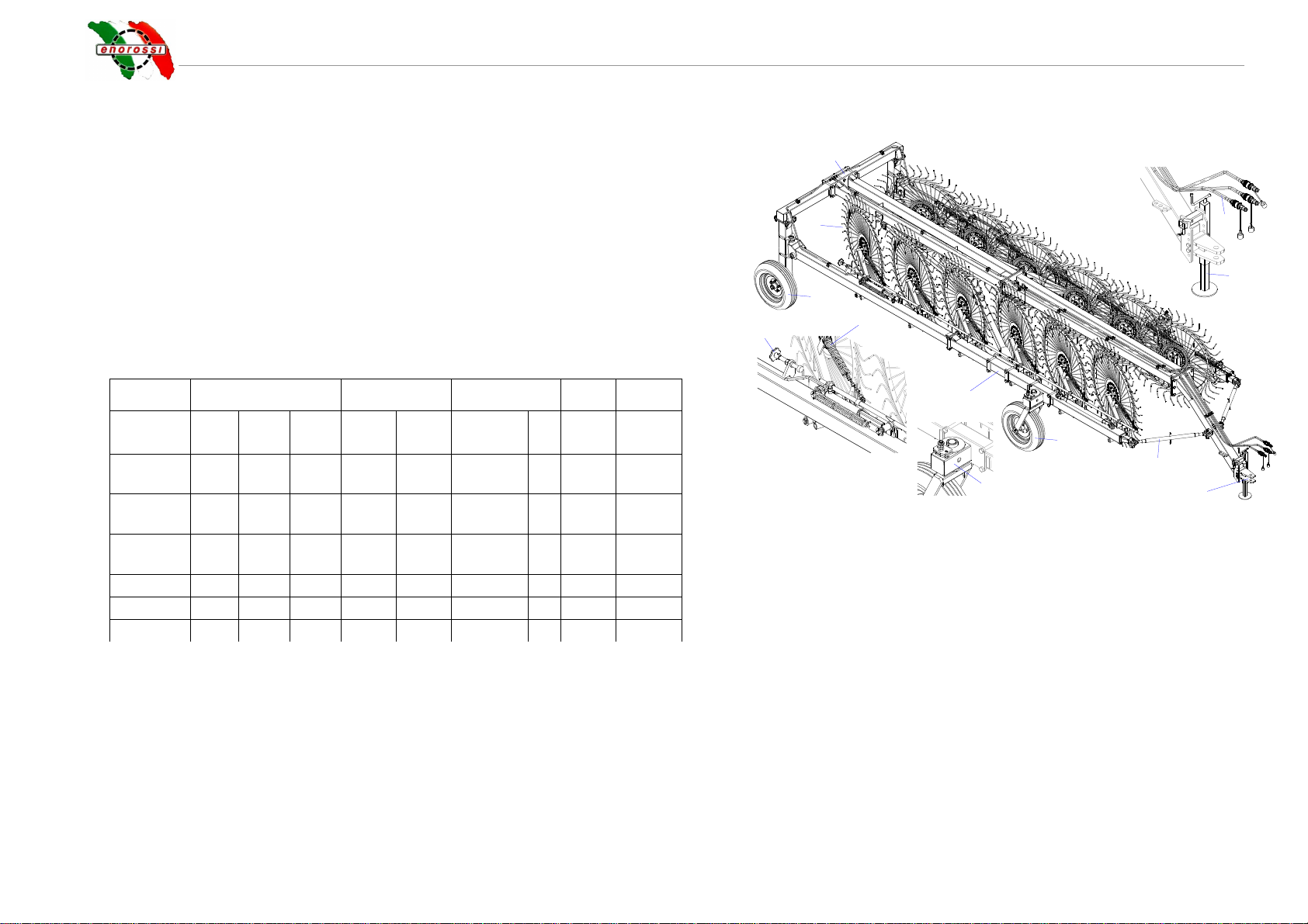
A5 Main components and technical specifications
1. Mechanical end stop (to adjust the rake wheel to the ground)
2. Shock absorbing spring
3. Rear wheel
4. Rake wheel
5. Frame
6. Hydraulic quick couplings
7. Supporting foot
8. Tractor coupling device
9. Tie rod (for road circulation)
10. Front wheel
11. Device to limit pivoting of the front wheel
12. Side arm
Model Stars Width Wheels HP Weight
N° Teeth Ø cm
Work
config
cm
Trnspt
config
cm
Type N°
Kg
Easy RAKE 16 40
149,
5 970 280
205/70.
15 8 50/60
2.250
Easy RAKE 18 40
149,
51.060 280 205/70.15 8 50/60
2.390
Easy RAKE 20 40
149,
51.150 280 205/70.15 8 50/60
2.549
2
1
3
4
5
6
7
8
9
10
11
12

Rev. 0 04.10
SAFETY
B1 General regulations
This manual describes the safety regulations to be followed when using
the rake. As most work-related accidents occur due to non-compliance
with the most basic of safety regulations, it is obligatory to read this
manual before carrying out any work with the rake and to follow all the
instructions.
The equipment must be used by qualified adult personnel trained in its use.
The Manufacturer therefore does not cover accidents caused by the
operator's negligence and/or non-compliance with the safety
instructions. This also forfeits the Manufacturer's responsibility and
the rake's warranty.
B2 Handling and transportation
•Transportation (delivery): the device is fully dismounted and placed in
a crate for transportation. The Customer can then re-assemble the
parts quickly and easily on receipt, following the well detailed
instructions. If the rake is sold or transferred to another user, the rake
can be dismantled by following the instructions in reverse order,
although it can also be delivered fully assembled. The rake can also
be easily transported by road on a suitable means of transport, as
illustrated below.
The rake is loaded or unloaded via a ramp attached to the vehicle. The
equipment, when ready for transportation, is reversed onto the vehicle,
then harnessed in place and fitted with all necessary safety devices for
transportation.
WARNING
Loading and unloading must always be carried out with all due
precautions as they can entail a certain element of risk.
Always take the following precautions:
- Loading/unloading must be carried out on a flat surface and at a
safe distance from slopes or ditches;
-Always ensure the ramps are strong enough to withstand the
rake's weight (given on the identification plate), are firmly attached
to the vehicle and are parallel to each other and perpendicular
with the edge of the vehicle;
-Ensure the ramps are clean, without any traces of oil, grease or
ice;
-Never change direction when moving the rake onto or off the
vehicle. If this does become necessary, bring the rake back down
to change its trajectory.
•Transportation (by road): as this is a trailer-type device, it can only
be transported if attached to an agricultural tractor. In this case, the
device must always be in its transportation configuration for
transportation either by road or in the fields, as illustrated below. This
configuration is necessary as the device can be up to 10 metres in
width in its working configuration.
CONFIGURAZIONE DA LAVORO CONFIGURAZIONE DA TRASPORTO
WORKING CONFIGURATION
TRANSPORTATION CONFIGURATION
8
Rev. 0 04.10
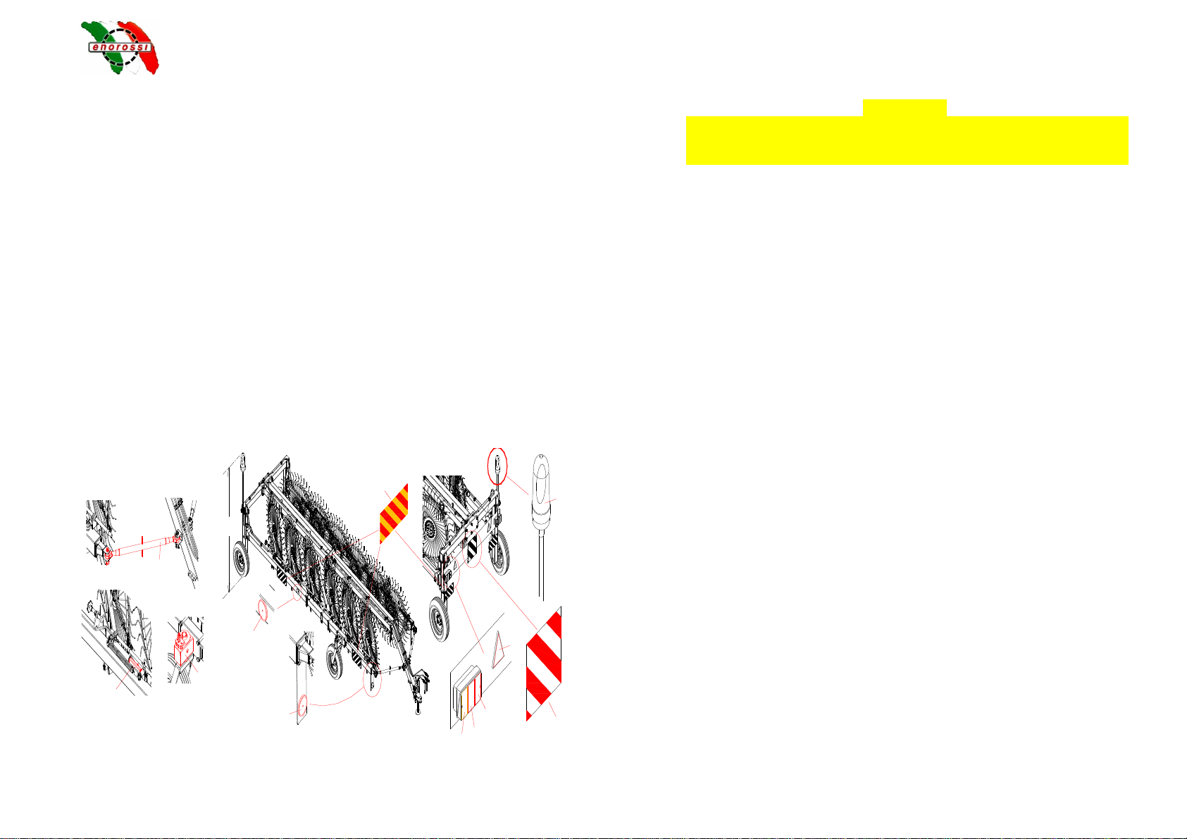
You must remember that the transportation configuration entails
closing the side arms and fitting the equipment with the following
safety devices:
-Tie rods (1) to be fitted in position on the arms and frame, and
locked in place with their relative safety pins;
-End stop device (2) to be inserted on the rod of the jack (to
prevent it from retracting) and blocked with its respective safety
pin;
-Device (3) on the front wheels to limit their movement;
You must also comply with your national road regulations.
•Installation: the device must only be installed on agricultural tractors
with universal three-point hitch system at the back and with hydraulic
lift.
IMPORTANT
The tractor must also, by law, be fitted with a protective roll-bar or
ROPS or FOPS cabin. It is strictly forbidden to install the rake
device on a tractor without the required protection.
Prior to installation, however, the Customer must check the tractor's
operating and maintenance manual to ensure the tractor is suited for
use and operation of the rake, and whether ballasts are needed to
prevent unbalancing that could cause it to tip over.
Instructions on installing the tiller and making the hydraulic
connections are given below.
2m
1
3
26131211 10
9
8
7
4

9
Rev. 0 04.10
Use: the rake must only be put to the use for which it was intended: to
rake up cut forage. Any other use is therefore improper and forbidden.
The rake's technical characteristics must also not be altered in any way to
modify performance otherwise the warranty will be forfeited
immediately and the Manufacturer will refuse all responsibility.
The rake must be used in conditions ensuring good light and visibility.
We recommend you do not work when light and visibility is poor as this
can compromise normal levels of safety. Recommence work only
when light and visibility is good again.
The rake does not require special attention during use as it is not
operated directly, being trailed by the tractor; the operator must,
however, ensure that no persons or animals come too close in the
interest of their safety.
In any case, the rake must only be operated by qualified and well
trained adult personnel who have read the instructions in this manual.
Safety is of paramount importance for personnel operating, repairing
or maintaining the device. As the instructions given in this manual
cannot cover all possible working situations and related risks,
personnel must always act with caution and with common sense.
The operator must take the following precautions when using the rake
device:
-The tractor must not be left running or unguarded, not even for
short periods. The operator must always switch off the tractor's
engine and take the key with him;
-The rake device is relatively quiet and does not require use of
acoustic protection (ear plugs, ear muffs, etc), although this may
not be the case with the tractor. We therefore recommend you
check this in the tractor's operation and maintenance manual.
B3 Operator's responsibilities and safety
Safety is of primary importance to personnel operating the rake device and
therefore each operator is directly responsible for controlling the rake's
operation, maintenance, repairs and/or use of spare parts or consumable
materials. This means the aforementioned personnel must never delegate
their work to operators without the necessary requisites.
The Manufacturer assumes no liability for:
-Improper or incorrect use of the rake device that can cause harm to
persons and animals or damage to objects and the actual rake;
-Employment of personnel who have not received proper training
and/or has not read and understood the instructions in this manual;
-Lack of or insufficient maintenance;
-Use of spare parts that are not type approved or not compatible with
the rake model;
In addition to the instructions in this manual, personnel are given visual
aids in the form of labels (shown in the illustration) attached to the front of
the rake device indicating the necessary safety precautions. These labels
are designed to attract the operator's attention and indicate the level of risk.
These labels, however, differ in shape and colour according to the
instructions. Personnel must therefore know that a circular label indicates
an obligation (blue and white) or a prohibition (red, white and black), and
a triangular label indicates a hazard (yellow and black). Rectangular labels
feature the hazard or prohibition symbol but also indicate the safety
precautions to be taken.
Warnings given on the labels:
a. Risk of flying objects. Objects in the field of operation may be caught
and thrown by the teeth of the rotating rake wheels;
b. Risk of snagging. As the rake wheel rotates, there is a risk that the
teeth snag on the operator's clothes or other objects on the operator's
body.

10
Rev. 0 04.10
c. Obligation to read the user and maintenance manual;
d. Prohibition for unauthorized persons to stand or move in the rake's
field of operation when the rake is being used. Persons must keep at a
safe distance and should they need to move in the rake's field of
operation, they must do taking all due precautions;
IMPORTANT
Warning labels and pictograms must be replaced if they become faded and
risk becoming illegible. In this case, the operator must not use the rake until
any faded labels are replaced with new ones. It is also strictly forbidden to
remove the pictograms and labels from the equipment. Should this occur,
the Manufacturer assumes no liability as the rake no longer meets the
safety requirements for which it was designed and created.

11
INSTALLATION
C1 Rake assembly
As mentioned above, the equipment is fully dismantled for delivery to the
Customer. The rake can be assembled quickly and easily following the
user-friendly instructions (see Page 18). Assembly must be carried out on a
flat surface prepared especially for the purpose. Assembly operators must
be knowledgeable of installation safety regulations and work with all due
care and attention.
The rake, once it has been assembled, can be installed or hitched to a
tractor.
C2 Hitching to the tractor
The rake can be hitched to the attachment of any agricultural tractor. To do
so, the operator must move the rake slowly to a position where the joints
can be easily aligned (1).
IMPORTANT
The holes in the tractor's attachment must be aligned with those on the
rake's attachment with maximum care and attention.
When the tractor is near the rake's attachment (type 1
or 2 – see picture), the operator turns the lever on the
foot support (2) to lift or lower the rake's attachment
and insert it in the tractor's attachment. The operator
can then insert the locking pin (3) through the
attachment holes, as illustrated below, and secure it in
place with the relative safety pin (4).
Next, the operator turns the lever (5) to lift the foot
support off the ground, completing the tractor-rake
attachment procedure. The foot support can then be
removed from its housing and inserted in the housing on the frame.
The operator therefore has to extract pin (6) to free pin (7), extract the latter
from the holes of the foot support and remove the foot support from its
housing (8). The foot support can then be placed in the housing on the
frame (9) and fastened with pin (7) and its relative safety pin.
C3 Hydraulic connections
•The rake wheels are lowered and lifted by retracting and extending a
jack, while the side arms are opened and closed hydraulically by
another jack. Both jacks are powered by the tractor's auxiliary circuit
and therefore commanded by their respective levers in the cabin. As a
result, these functions can only be carried out if the jack connections
1
2
tipo 1
tipo 2
3
4
5
6
78
9

12
are made (quick couplings, as illustrated) to their corresponding
attachments on the tractor's auxiliary circuits.
C4 Removal
To remove the rake from the tractor, follow the above instructions in
reverse order. The hydraulic connections have to be removed before the
actual rake.
C5 Storing the rake
The Customer must set aside a large and easily accessible area on his
premises where the rake can be stored. How to store the rake:
-Park the rake in a safe area set apart for the purpose. The area must
be flat and even;
-Install the foot support supplied with the rake and stored in its relative
housing on the frame, near the attachment;
-Detach the rake from the tractor, following the instructions in
paragraph C2 and C3 in reverse order;
-Chock the wheels;
-Place protective material over the rake.

13
OPERATION and USE
∆1
∆1∆1
∆1
Preliminary information
Suitable and optimal use of the rake not only helps avoid accidents but is
also the only way to ensure high yield and make use of the rake's full
potential and performance.
The rake must be used by trained adult personnel knowledgeable of the
instructions in this manual and on the labels. Safety is of paramount
importance for the personnel that operate, repair and maintain the
equipment. As the instructions given cannot possibly cover all possible
working situations, personnel must always exercise caution and common
sense.
Before the tractor can transport the rake to the work area, it is advisable to
carry out the following preliminary checks:
•Ensure all the parts of the rake are in their intended position and are
securely fitted;
•Ensure the rake is fitted properly to the tractor;
•Check efficiency of all the protection devices;
•Carry out the daily maintenance checks described in the relative
paragraph. Note: should the rake be returned to service after a long
period of inactivity, ensure it has been properly maintained and that it
has not been damaged in any way by poor weather or storage
conditions.
∆2
∆2∆2
∆2 Operation and use
The rake must be taken to the work area in keeping with the instructions in
paragraph B2 “Handling and Transportation”.
The tractor driver is personally responsible for the general procedure of
conveying the rake and must therefore prepare the rake for transportation
as follows:
•Firstly, the operator must remove any safety devices that need to be
removed for transportation, i.e. The jacks' end stop devices (B) and
the arms' tie rods (A):
-End stop device: remove the safety pin to free the device, lift the
latter from the jack rod and move it further back, as shown in the
illustration. Re-fasten the device with the safety pin (do one side
at a time);
-Arms' tie rods: remove the safety pin from the locating pin and
remove the latter from its housing. Repeat the same procedure
on the other side of the tie rod and then remove it from the
rake's pinned supports. Move the tie rod to the points on the
frame shown in the illustration. Screw the body of the tie rod into
place at the new points.
•After removing the safety devices, the operator uses the respective
controls in the cabin to fully open the rake’s arms (control A) into
the working configuration, and then lower the rake wheels (control
B), which all move together, as shown in the illustration.
B
A

14
The rake is now ready for use. It is extremely easy to operate as it just has
to be hitched to the tractor which trails it in the required direction. The rake
wheels, which have been adjusted according to the type of ground, turn as
they are pulled along and the teeth
collect the cut forage.
The rake’s working configuration, as
illustrated, allows the cut forage to
be collected and conveyed into a
single central swath. This
configuration, which can reach 10
metres for some models,
considerably simplifies the process
thereby reducing end costs.
IMPORTANT
You must remember that the tractor
must drive in a more or less straight
line. To change direction a few
metres before the end of the field,
the driver needs to apply the
command to lift the rake wheels and
close the side arms.
Only after the rake wheels have
been lifted and the arms are closed
can the operator change the
tractor’s direction, which requires
several maneuvers.
Once the operator has turned the tractor, he can apply the command to re-
open the side arms and then lower the rake wheels to continue the work.
To move the forage in the central swath, one or more additional rake
wheels need to be installed at the centre of the frame. A set of additional
rake wheels can be supplied with the Easy Rake series (the set, shown in
the illustration, is called Kicker wheel and is available on request).
Swath adjustment: the swath can be narrowed by moving the two rear
rake wheel arms, as indicated in the illustration by the arrow.
Easy Rake with Kicker wheel
CONTROL A
CONTROL B

15
Kicker wheel adjustment
After installing the kicker wheel (assembly instructions on page 40), the
rake wheels can be better adapted to the ground by adjusting their
inclination in relation to the direction in which they move:
Loosen the counter nut (pos 2) and screw or unscrew the bushing (pos 3)
to increase or decrease inclination of the two rake wheels.
1) Decreased inclination FIG. 1: hay is discharged
better from the rake wheels, but the ground isn’t
cleared as efficiently.
2) Increased inclination FIG. 2: hay isn’t discharged as
efficiently from the rake wheels, but the ground is
cleared better.
Figure 1 Figure 2
Prior to work breaks (even short ones) the operator must always:
•Switch off the tractor’s engine
•Apply the parking brake
•Place the gear stick in neutral
•Remove the keys from the ignition;
When the operator has finished work for the day, he must place the rake
back in its transportation configuration before returning the tractor to its
parking area.
Rake storage instructions are given in paragraph C5.
Kicker wheel

16
MAINTENANCE
E1 Maintenance instructions
The Manufacturer has drawn up a rake maintenance schedule based on
functional tests. This schedule, if followed assiduously by the Customer,
can maintain the rake’s working efficiency and capacity without risk of
damage. The operator, who must be a qualified technician of working age,
must follow these rules:
-All maintenance and repairs must never be left unfinished or
postponed;
-The operator must never rely on his memory alone, but always read
and follow the instructions in this manual without fail;
-The operator must install a “Maintenance in progress” sign in a
prominent position on the tractor’s dashboard before starting work. This
ensures the operator’s safety and can prevent damage to the rake.
-All maintenance must be carried out on a flat and well lit surface, with
the rake standing in a stable position and the tractor at standstill, with
the parking brake applied, the engine off and the keys removed from
the ignition;
-Tools for maintenance must be used in accordance with relative
accident prevention regulations. Equipment must not, therefore, be put
to improper use, e.g. do not use petrol instead of detergent, or pliers
instead of a wrench;
-Only use spare parts that are type approved or recommended by the
Manufacturer.
After maintenance or repairs, always clear the area of any water, oil,
grease, dirty cloths, tools and any other material.
IMPORTANT
Take extra care when checking for leaks of pressurized fluid as the fluid
can leak out of tiny, virtually invisible holes, burn through skin and cause
serious infections. You must therefore use safety glasses with side
protection and a piece of cardboard or wood to look for leaks.
E2 Scheduled maintenance
Scheduled maintenance is purely informative and depends on normal
operating conditions. It may therefore differ in relation to the type of
service, working environment (which may be dusty), the season, etc.
Maintenance should be stepped up the tougher the machine’s operating
conditions.
E2.1
Checks on a daily basis
Checks to be carried out on a daily basis:
-
Check condition of all the labels;
-
Check condition of all the fittings (tightness of connections,
condition of sleeves and leaks or overflowing of hydraulic oil);
-
Use a grease pump to re-fill all the greasers on the equipment,
or apply grease with a brush where necessary;
-
Ensure all the nuts and bolts are properly fastened.
E2.2
Checks on a monthly basis or per 50 hours’ operation
Checks to be carried out on a monthly basis or per 50 hours’
operation:
-Check condition of all the labels;
-Check condition of all the fittings (tightness of connections,
condition of sleeves and leaks or overflowing of hydraulic oil);
-Check presence and condition of fasteners and safety devices;
-Ensure all the nuts and bolts are properly fastened;
-Check condition of the entire structure.
E2.3
Checks on an annual basis or per 500 hours’ operation
Checks to be carried out on an annual basis or per 500 hours’
operation:
-Check condition of all the fittings (tightness of connections,
condition of sleeves and leaks or overflowing of hydraulic oil);
-Check presence and condition of fasteners and safety devices;
-Ensure all the nuts and bolts are properly fastened;
-Check condition of the entire structure.

17
E3 Lubrication
To top up the greasers, remove their protection caps (if
present), remove all traces of dust and then use the
pump to inject the grease. Afterwards, use a cloth to
remove any excess grease on the greasers. Use a
brush to apply grease wherever there aren’t any
greasers.
All grease top-up points on the rake are indicated by
labels like the one shown in the illustration.
IMPORTANT
To avoid pollution, it is strictly forbidden to dispose of
oil, lubricants, filter cartridges or other noxious
materials in the environment. Comply with all
regulations in force on disposal of liquid and solid substances.
E4 Troubleshooting
The jack activation
command does not
respond
Hydraulic oil level
low
Hydraulic system
piping is damaged
Hydraulic pump is
damaged
Filter is clogged
Top up oil level
Replace piping
Replace pump
Replace filter
The jacks only move
intermittently
Air in the hydraulic
circuit
Operate the pump at
no load for a few
minutes, using the
jacks, to expel any air
in the hydraulic
circuit.
The jacks move even
when the command
isn’t given
Jack seals are worn
out
Replace seals
Overheated oil
Filter is clogged
Pipes are crushed
Oil level low
Replace filter
Check and replace
pipes
Top up oil level
Oil loss
Slow connection
Worn out seal
Squeeze the pipe
Replace the seal
Note: contact the Manufacturer about any faults or trouble not mentioned
in the table.
E5 Machine demolition: disposal of materials
When the rake is placed out of service, you must make harmless all parts
that could pose a safety risk to persons, animals and the environment
when sent for disposal. Materials that make up the rake and should be set
aside for segregated disposal are:
-Iron
-Hydraulic oil
-Rubber
-Plastics
These materials must be disposed of in compliance with relative national
legislation in force.
PUNTI DA
INGRASSATORI
LUBRIFICARE

18
Rev. 0 04.10
5
1
23
4
2
6
7
IM1 ERS 16-18-20
Machine assembly instructions
Assembly 1
For Easy-Rake SUPER STAR 16-18-20
A) Connect the cross drawbar
Pos. 1 to the rear pullbar
Pos. Fix the 920x230x15
plate Pos. 3 using the 10
T.E. M20x200 screws Pos.
4 and the M20 self-locking
nuts Pos. 2.
B) Connect the central pullbar
Pos. 7 with the rear pullbar
Pos. 5. Fix using the T.E.
M20x55 screws Pos. 6
and the M20 self-locking
nuts pos. 2.

19
Rev. 0 04.10
IM2 ERS 16-18-20
8
7
9
10
8
9
11
MOD. ERS18
MOD. ERS20
A
B
Assembly 2
For Easy-Rake SUPER STAR 16-18-20
A) Connect the pullbar
Pos. 10 with the rear
pullbar Pos. 7. Fix
using the six T.E.
M20x55 screws Pos. 9
and the M20 self-
locking nuts pos. 8.
B) Connect the front
pullbar Pos. 11 with
the pullbar Pos. 10. Fix
using the six T.E.
M20x55 screws Pos. 9
and the M20 self-
locking nuts pos. 8.
20
Rev. 0 04.10
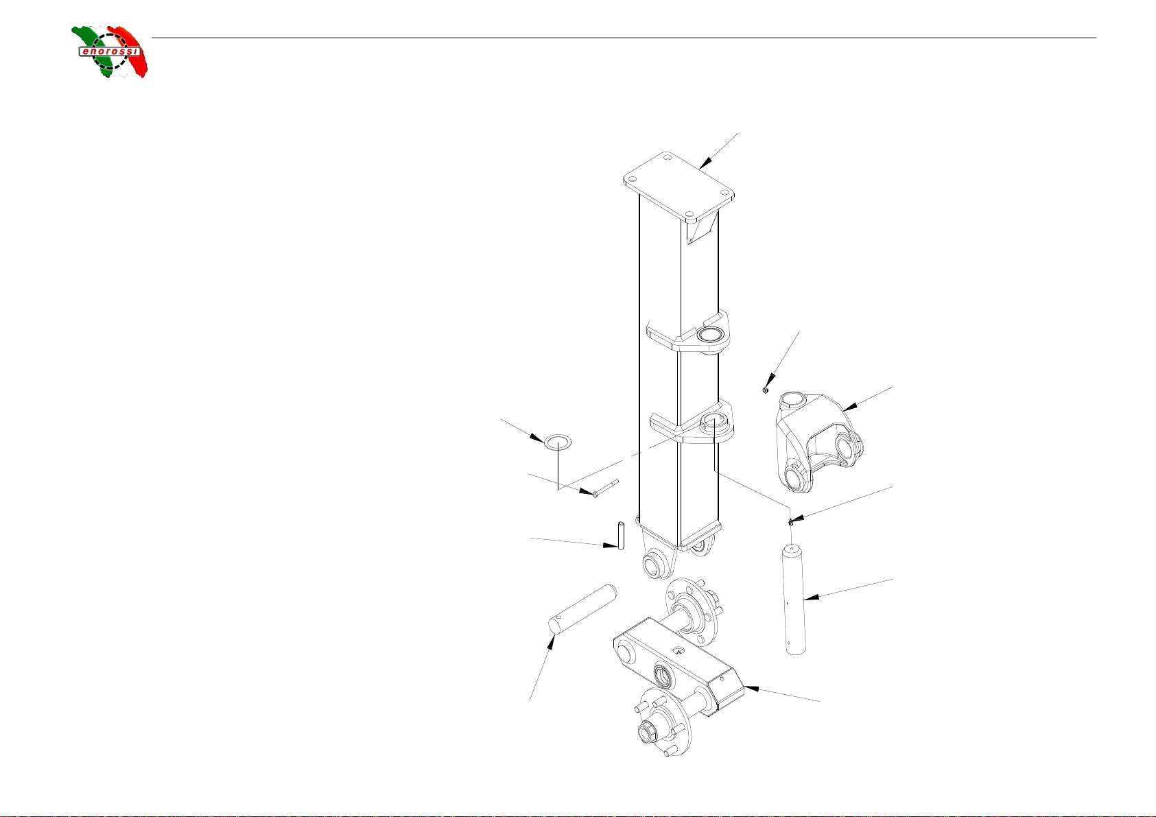
IM3 ERS16-18-20
12
14
13
17
18
19
20
21
15
16
Assembly 3
For Easy-Rake SUPER STAR 16-18-20
A) Assemble the joint for the right and left frame Pos. 14
into the right and left leg support Pos. 12, by placing
the antisiezure fifth wheel AS 5070 Pos. 21 under the
joint bush and on the leg support bracket. Insert pin
Ø50x297 Pos. 16 and fix it with T.E. M8x80 screw
Pos. 20 and M8 self-locking nut Pos. 13.
B) Assemble the tandem axle Pos. 17 in leg support
Pos. 12, insert pin Ø42x220 Pos. 18. Fix with circlip
Ø14x75 Pos. 19.
This manual suits for next models
2
Table of contents
Other enorossi Farm Equipment manuals

enorossi
enorossi RAKE CADDY Series Operating instructions

enorossi
enorossi DR 420 4R User manual

enorossi
enorossi ENOSPE US User manual

enorossi
enorossi RR 350 EVO PROFI User manual

enorossi
enorossi G4V-3P User manual

enorossi
enorossi MAXIMUS 12 User manual

enorossi
enorossi G2 Series User manual

enorossi
enorossi ENODUO TRACER 780 User manual

enorossi
enorossi HAY TOP 300 User manual

enorossi
enorossi RR 400 EVO Series User manual


