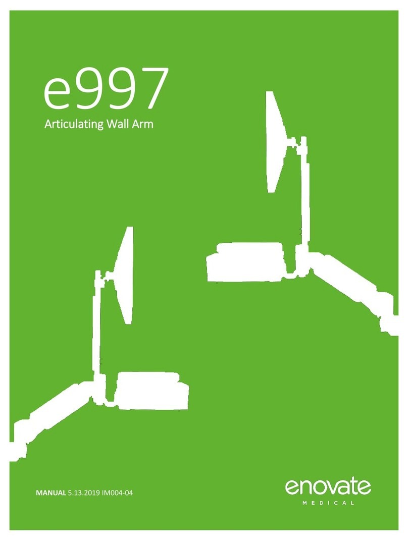
Enovate Medical e997 User manual

MANUAL | IM002-Rev004 10.25.23
e997
Articulating Wall Arm

1
The Enovate Medical e997 Wallstation was designed to set a new standard in qual-
ity. Enovate Medical’s goal is to provide a wallstation that is ready for years of use, and
backed by a commitment of exemplary service and support.
Thank you for purchasing the
Enovate Medical e997 Wall Arm!

Warnings • e997 MANUAL
23
• e997 MANUAL
The symbols below represent safety warnings that require significant
attention when seen on this product or in this user manual. Failure to
follow these warnings could result in minor injury, major injury, or even
death,
WARNINGS
Important Warnings Electrical Shock Warning
CONTENTS
WARNINGS....................................................................................................................................... 3
SERVICE AND REPLACEMENT....................................................................................................... 4
HARDWARE & COMPONENTS........................................................................................................ 5
OPTIONAL COMPONENTS .............................................................................................................. 6
HARDWARE INCLUDED .................................................................................................................. 7
TOOLS REQUIRED............................................................................................................................ 8
MOUNTING....................................................................................................................................... 10
WALL TRACK MOUNTING ALL OPTIONS: ................................................................................... 11
TOGGLE MOUNTINGPREFERRED MOUNTING METHOD .................................................................................................................................................12
TOGGLE MOUNTING CONTINUED ........................................................................................................ 13
METAL STUD
MOUNTING
20 GAGE .035" OR HEAVIER METAL STUD..........................................................................................................................14
WOOD STUD MOUNTING HARDWARE NOT INCLUDED..............................................................................................................................................15
CARRIAGE ARM MOUNTING NONEXTENSION ARM .............................................................................................................................................16
CARRIAGE MOUNTING EXTENSION ARM ......................................................................................................................................................................17
RISER ARM, MONITOR POLE, EDESK AND SIMPLE KEYBOARD TRAY ASSEMBLY................... 18
MOUNTING THE MONITOR.............................................................................................................. 22
KEYBOARD INSTALLATION............................................................................................................ 23
STANDARD KEYBOARD CABLE MANAGEMENT........................................................................... 22
EDESK CABLE MANAGEMENT....................................................................................................... 23
RISER ARM CABLE MANAGEMENT ............................................................................................... 26
ROUTING CABLES THROUGH THE WALL TRACK......................................................................... 28
ROUTING CABLES THROUGH EXTENSION ARM........................................................................... 29
INSTALL THE END CAP OR CPU BRACKET ................................................................................... 30
INSTALL THE END CAP OR CPU BRACKET CONT .......................................................................... 31
RISER ARM TENSION ADJUSTMENT............................................................................................ 32
WORK SURFACE AND MONITOR LEVELING.................................................................................. 33
KEYBOARD TILT .............................................................................................................................. 34
MOUNTING MOUSE HOLDER STANDARD SIMPLE KEYBOARD TRAY.................................................................. 35
ARM EXTENSION............................................................................................................................. 36
KEYBOARD TILT .............................................................................................................................. 36
MONITOR TILT.................................................................................................................................. 36
RANGE OF MOVEMENT WITH EXTENSION ARM ......................................................................................... 37
RANGE OF MOVEMENT NO EXTENSION ARM ............................................................................................ 38
PARTS LIST ...................................................................................................................................... 41
Read the entire installation manual before you begin.
Mounting
Installer must verify that the entire wall will safely support the
combined weight of all attached equipment and hardware. Improper
installation of this product can cause extensive property damage or
serious personal injury, either during or after installation. It is the
responsibility of the installer to ensure that all applications including
wood, concrete, block, brick, steel, etc. are secured properly and
are in compliance with local and national building codes. California
installations could require specific anchorage, and additional mounting
screws. Check with local authorities for codes in your area. Other
seismic states have similar regulations.
WARNING:
Because wall surfaces and construction methods and materials vary,
it is imperative that you consult with the appropriate engineering,
architectural, or construction professional to ensure that your wall
computing station is mounted properly to handle the applied loads
ELECTRICAL SHOCK HAZARD:
Cutting or drilling into electrical wires and cables can cause FIRE,
DEATH or SERIOUS PERSONAL INJURY. Always make certain the area
behind the mounting surface is free of electrical wires and cables
before drilling into wall.
EXPLOSION AND FIRE HAZARD:
Drilling into gas plumbing can cause EXPLOSION, FIRE, DEATH or
SERIOUS PERSONAL INJURY. Always make certain the area behind
the mounting surface is free of gas, water, waste, or any other
plumbing before drilling into wall.
WARNING:
Weight restrictions apply. See table on page 5 for more information.

Hardware & Components • e997 MANUAL
45
Warnings • e997 MANUAL
Riser Arm
Part Number
If desk type
is:
COMBINED
WEIGHT* of
equipment
(monitor, AIO,
printer, scanner,
badge reader,
etc.) must not
exceed:
If Desk Type
Is:
COMBINED
WEIGHT* of
equipment
(monitor, AIO,
printer, scan-
ner, badge
reader, etc.)
must not ex-
ceed:
AM0400008
(700N light duty)
Product Code
Standard 12 lbs. eDesk Not Available
AM0400157
(850N medium duty)
Standard 22 lbs. eDesk 15 lbs.
AM0400171
(1050N heavy duty)
Standard 36 lbs. eDesk 29 lbs.
SERVICE AND REPLACEMENT
Warranty will be void if an attempt to service or replace any part of the Enovate Medical Wall
Arm is made unless directed to do so through Enovate Medical approved documentation (i.e.,
this User Manual or other instructions). Only Enovate Medical or an Enovate-certified entity
may service or replace the Enovate Medical Wall Arm components. If any component on the
Enovate Medical Wall Arm is missing or damaged, the Wall Arm must not be used. Contact
Enovate Medical immediately to request service.
If the unit is not working properly, please contact Enovate Medical customer service via your
computer or phone at the locations shown below.
enovatemedical.com/support
888.909.8930 toll free
RISER ARM WEIGHT RANGE
Description Part Number
1. Wall Track (32", 42", 48") 32" AM0200022 42" AM0200098 48" AM0200027
2. Wall Track End Caps (2x) AM0700001
3. Wall Track Cable Cover 32" AM0200092 42" AM0200110 48" AM0200109
4. Monitor Pole Assembly A0001216
5. Carriage and Knuckle Assembly AM0400012
6. Riser Arm and Cable Cover AM0400163 (700N light duty)
AM0400157 (850N medium duty)
AM0400171 (1050N heavy duty)
AM0800006 (cable cover)
7. Simple Keyboard Tray AM0400102
8. Mouse Holder Simple Tray HC0400305
9. Adhesive Mouse Pad AM0100050
HARDWARE & COMPONENTS
The 8th Digit in the product code number on your invoice denotes spring strength. In the
example below the 8th number is "8", this unit has an 850N gas spring.
IMPORTANT: Please refer to your invoice for the product code number to determine what
Riser Arm you have.
Product code: e997N0-E-803-WC-0 = 850N
0in 8th position = 700N
8in 8th position = 850N
1in 8th position = 1050N
If invoice is not available please retrieve serial number from the mount and contact
Technical Support at (888)-909-8930
STANDARD COMPONENTS
3
1
4
5
6
82
7
9
WEIGHT RESTRICTIONS

Hardware & Components • e997 MANUAL
67
Hardware & Components • e997 MANUAL
OPTIONAL COMPONENTS
Description Part Number(s)
1Extension Arm and Cable Cover AM0400007 (arm)
AM0200090 (cable cover)
2Small CPU Bracket AM0400030
3CPU Bracket Thumb Screw AM0100039
4eDesk AM0400100
5Large Locking CPU Enclosure Box HC0400392
6Small Locking CPU Enclosure Box HC0400884
Note: These optional CPU enclosures are
mounted using the instructions for the small
CPU bracket, as shown on page 22.
OPTIONAL COMPONENTS
HARDWARE INCLUDED
6-8x*
SNAPTOGGLE® Anchor
Part WS0900200
6-8x*
1/4" 20 x 2 1/2"
Cross Drive Metal Screw
(for use with SNAPTOGGLE
installations)
Part CR-PHMS 1/4 -20 x 2.5 x ZNC
2x
Large Plastic Washer
Part AM0800009
6-8x*
1/4" x 1"
Wide Flat Washer
Part SWFW 1/4 x 1.00
TYPE A ZNC
1x
3/4-10 Nut
Part P0001839
1x
Shim Washer
Part P0001840
4x
10-24 x 1/2"
Button Head Screw
Part BHSC 10-24 x .500 x .500
SS
4x
M4 x 16mm
Pan Head Screw
Part CR-PHMS M4 x
4x
1#10 x1/4
Standoff
Part HC0100167
1x
(Pre-installed on the
riser arm) Large Slotted
Pan Head Screw
Part AM0700047
1 Length
Cable Loom
Part P0000119
4x
Dual Lock Pads
Part P0000050
5x
(Shown with cable tie)
Cable Tie Adhesive Pad with Zip Tie
Part WS0900092
1
6
3
4
5
2
Zip Tie
Adhesive Pad

ASSEMBLY • e997 MANUAL
89
Hardware & Components • e997 MANUAL
TOOLS REQUIRED
Level
1/2” Drive Torque Wrench
1/2” Drive 1 - 1/18” Socket
Drill
1/8”
Allen Wrench
4mm
Allen Wrench
3/16”
Allen Wrench
5/16
Allen Wrench
Flat Head Screwdriver
Tape Measure
Stud Finder Phillips Head Screwdriver
Pencil
IMPORTANT BEFORE YOU BEGIN INSTALLATION:
Enovate Medical does not recommend installation of its wall mounted
product to drywall only. This product should be mounted to metal or wood
studs or on ¾” plywood backing board securely mounted to studs. Do
not mount to floating studs. Use the appropriate fasteners to secure wall
track to a stud or backing board. Toggles are recommended as the safest
mounting method if installed according to manufacturers recommendations.

Mounting • e997 MANUAL
10 11
Mounting • e997 MANUAL
Figure #1
MOUNTING
The following procedures must be performed as described to ensure proper
installation.
NOTE: Always mount the e997 to a wall stud or 3/4" plywood backing board
that is securely mounted to studs. Do not mount to floating studs.
STEP 1
Install the wall track end cap to the bottom of the wall track using two 10-24
x 1/2" Button Head Screws using a 1/8" Allen Wrench.
1. Align the holes on the wall track end cap with the corresponding holes on
the wall track.
2. Secure the end cap to the wall track using the two 10-24 x 1/2" Button
Head Screws. Ensure they are tightened firmly but do not over-tighten.
NOTE: Once the end cap is securely in place, you can proceed with mount-
ing the track to the wall.
WALL TRACK MOUNTING ALL OPTIONS:
Wall Stud
Wall Stud
10"
1"
8.5"
10"
8.5"
1.5"
6"
1"
1”
1.5”
Wall Stud
32”
Wall Track
X
Y
Z
1”
42”
Wall Track
48”
Wall Track
X Y Z
Max Keyboard Height Min Keyboard Height Mounting Height
46" 32" 36.5"
42" 28" 32.5"
38" 24" 28.5"
Item Part Number SNAPTOGGLE®
Quantity
48" Wall Track AM0200027 8
48" Wall Track Cable Cover AM0200109
42" Wall Track AM0200098 7
42" Wall Track Cable Cover AM0200110
32" Wall Track AM0200022 6
32" Wall Track Cable Cover AM0200092

ASSEMBLY • e997 MANUAL
12 13
ASSEMBLY • e997 MANUAL
STEP 2
Using a stud finder, locate a stud where the wall track will be mounted.
STEP 3
Determine the desired keyboard height. Use the chart on page 10 for standard
keyboard heights; adjust vertical dimensions as required for desired keyboard
height. Locate the exact center line of the wall stud where the track will be
mounted. Using a level, mark the center line and also the line where the bottom
of the track will be located off the floor.
STEP 4
Make sure that the wall track is
level and that the holes align with
the center line and bottom of track
line drawn in Step 3, mark the holes
for drilling. Set the wall track aside.
1/2”
3/8” - 3 5/8”
Thick
Must be 1-7/8” minimum
clearance behind wall for
channel rotation.
1/2”
3/8” - 3 5/8”
Thick
Must be 1-7/8” minimum
clearance behind wall for
channel rotation.
1/2”
3/8” - 3 5/8”
Thick
Must be 1-7/8” minimum
clearance behind wall for
channel rotation.
Patented under one or more of the following U.S. Patent Nos.: 4,993,901; 5,028,186; 5,161,296; 5,938,385; 6,161,999;
7,144,212; 7,320,569; and foreign counterparts thereof and of 4,650,386 and 4,752,170. Other patents pending. TOG-
GLER and typeface, symbol, TA, TB, TC, TH, ALLIGATOR, SNAPTOGGLE, and SnapSkru are worldwide registered
trademarks of Mechanical Plastics Corp.
TOGGLE MOUNTINGPREFERRED MOUNTING METHOD
STEP 1
Install the wall track end cap to the wall track using two 10-24 x 1/2" Button
Head Screws. (See Figure 1 Page 11)
STEP 6
Snap straps at wall by pushing side
to side, snapping off straps level with
flange of cap.
TOGGLE MOUNTING CONTINUED
STEP 5 - Continued
Hold the SNAP-TOGGLE® with the metal channel flat alongside its plastic
straps. Carefully slide the metal channel of the SNAP-TOGGLE® through
the drilled hole. Ensure the strap ends of the SNAP-TOGGLE® are flush and
aligned correctly. They should not be offset from each other.
Hold the strap ends between your thumb and forefinger. Gently pull the strap
ends toward you. Continue pulling until the metal channel sits flush against
the backside of the wall.
Using your free hand, slide the plastic cap along the straps. Continue sliding
until the flange of the cap sits flush with the wall's surface.
STEP 5
Using a drill, create a ½" hole for each
marking made in STEP 4. Ensure that
each drilled hole is free from debris
such as insulation and drywall dust. You
can use a small brush or a vacuum to
effectively remove any particles.

Assembly • e997 MANUAL
14 15
Assembly • e997 MANUAL
METAL STUD
MOUNTING
20 GAGE .035" OR HEAVIER METAL STUD
2
1
WOOD STUD MOUNTING HARDWARE NOT INCLUDED
Description Part Number
11/4-14 x 4" Hex Head Wood Screw* HX-WLAG.25 x 4.0 ZNC
2Wide Flat Washer SWFW 1/4 x 1.00 TYPE A ZNC
* This part may be ordered from Enovate Medical. Please see PARTS ORDERING
information on page 31.
2
1
Description Part Number
11/4-14 x 2 1/2"
Hex Head Self Tapping Metal Screw
HX-WHDS .25-14 x 2.5 ZNC
2Wide Flat Washer SWFW 1/4 x 1.00 TYPE A ZNC
STEP 2
Follow steps on page 12 for toggle mounting. (It is not recommended to
use self tapping screws if the studs are less than 20 gauge). Determine the
desired keyboard height. (Refer to chart on page 10) for standard keyboard
heights; adjust vertical dimensions as required for desired keyboard height.
STEP 3
Align the wall track matching the toggles installed on page 12. Secure the
wall track using the 1" wide metal washer and the 1/4-20 x 2-1/2" metal
screws included in the install kit. It is recommended to hand start and finish
these screws as they are very easy to cross thread and to strip out.
METAL STUD MOUNTING (20 GAGE ( 035") OR HEAVIER METAL STUD using
self tapping screws)
STEP 4
To begin, follow steps 1 through 4 on page 12.
STEP 5
Place the track against the wall and secure with the Wide Flat Washer, the
Hex Head Self Tapping Metal Screw. DO NOT DRILL PILOT HOLES.
NOTE: Ensure track is level before fully tightening screws. DO NOT OVER
TIGHTEN SCREWS.
STEP 1
BEFORE MOUNTING THE TRACK TO THE WALL install the wall track end
cap to the wall track using two 10-24 x 1/2" Button Head Screws. (See Figure
1 Page 11)
STEP 1
BEFORE MOUNTING THE TRACK TO THE WALL install the wall track end
cap to the wall track using two 10-24 x 1/2" Button Head Screws. (See Figure
1 Page 11)
STEP 2
Determine your desired keyboard height. Use the chart on page 10 for
standard keyboard heights; adjust vertical dimensions as required for
desired keyboard height.
STEP 3
Locate the exact center line of the wall studs where the e997 wallstation
will be mounted along with the bottom of the track height from the floor.
STEP 4
Using a level, mark the hole locations and the bottom of the track.
STEP 5
Drill a 3/16" pilot hole into each of the marked mounting locations. Use the
Wide Flat Washer and the Hex Head Wood Screw to secure the track to the
wall.
NOTE:
Ensure track is level before fully tightening screws. DO NOT OVER TIGHTEN
SCREWS.
For stripped holes in metal studs, see page 12.

Assembly • e997 MANUAL
16 17
Assembly • e997 MANUAL
STEP 1
Level the wall track. Tighten all toggle
screws adequately and according to the
manufacturers recommendations of no
more than 5ft/lbs.
CARRIAGE ARM MOUNTING NONEXTENSION ARM
STEP 2
Remove the wall track cable cover (you
will replace later). Ensure the four (4)
screws on the carriage and knuckle
assembly are loosened with a 3/16" Allen
wrench and slide the carriage and knuckle
assembly to the bottom of the wall track
NOTE: You may need to pull the carriage
and knuckle assembly towards you while
sliding.
STEP 3
Level and secure the screws tightly
with 1/4" Allen wrench.
Carriage Knuckle Assembly STEP 2
Remove the wall track cable cover (you
will replace later). Ensure the four (4)
screws on the carriage and knuckle
assembly are loosened with a 3/16"
Allen wrench and slide carriage and
knuckle assembly with extension arm
to the bottom of the wall track.
CARRIAGE MOUNTING EXTENSION ARM
STEP 3
Level and secure screws tightly
with 1.4" Allen wrench.
STEP 1
Level wall track and remove the wall
track cable cover.
Wall Track
Cover
Wall Track
Wall Track Cover
Wall Track
Carriage Knuckle Assembly

Assembly • e997 MANUAL
18 19
Assembly • e997 MANUAL
RISER ARM, MONITOR POLE, EDESK AND SIMPLE
KEYBOARD TRAY ASSEMBLY
STEP 1:
Remove the VESA mount from the monitor pole,
loosen the thumb screw on the collar and slide the
VESA mount up and off the monitor pole.
Note: You may need to press the small black safety
button in order to release the VESA mount.
STEP 2:
Slide the large plastic washer
(AM0800009) onto the threaded shaft
of the monitor pole.
Safety Button
Plastic Washer
AM0800009
Monitor pole shaft
Monitor Pole
Thumb Screw
VESA
Mount
2nd Plastic Washer
(AM0800009)
Monitor Pole Assembly
Keyboard Assembly
Riser Arm Assembly
Pivot Mount
STEP 4
Slide the monitor pole through the Riser Arm assembly. Add the 2nd large
plastic washer (AM0800009) and continue to slide the monitor pole through
the Keyboard assembly pivot mount.
STEP 3
Lay the eDesk or simple keyboard on a flat surface. Ensure the pivot
mount is facing you and pointing upward.

Assembly • e997 MANUAL
20 21
Assembly • e997 MANUAL
STEP 5
Slide the shim washer (P0001840) onto the end of the monitor pole. Begin
hand threading the 3/4-10 Nut (P0001839) turning it slowly to ensure proper
alignment and avoid cross threading.
STEP 6
Using a 1/2" drive torque wrench and a 1 -1/8th socket, tighten the nut to the
point where the riser arm will hold in place at the 1 o'clock position and then
with a slight push it will slowly fall down to its lowest point. Usually this is
between 5-8 foot-pounds.
Shim Washer
Nut
Riser Arm Assembly
(P0001840)
(P0001839)
Pivot Mount
Monitor Pole Assembly
(AM0800009)
(AM0700047)
(AM0700047)
Large Slotted Pan Head Screw
Plastic Washer
(AM0800009)
Riser Arm
Extension Arm
STEP 4
INSTALLATION WITH EXTENSION ARM
Insert riser arm stem through plastic washer into extension arm and
secure with large slotted panhead screw (AM0700047)
STEP 4
INSTALLATION WITHOUT EXTENSION ARM
Insert riser arm stem through the
plastic washer into the knuckle
and carriage assembly and secure
with large slotted panhead screw
(AM0700047)
VERY IMPORTANT: THE BASE TORQUE IS 5ft-lbs WITH A MAXIMUM OF 8ft-lbs.)
OVER TORQUING WILL RESULT IN DAMAGE TO THE MONITOR POLE STEM.
NOTE:
When tightening the 3/4-10 Nut, hold the monitor pole straight with the
keyboard tray (or eDesk). This will ensure the monitor is aligned correctly
with the simple keyboard tray (or eDesk).

Cable Management • e997 MANUAL
22 23
Assembly • e997 MANUAL
NOTE: You may need to press the
small black safety button on the
monitor pole assembly to slide it
into place.
Dual Lock Pads
(P0000050)
MOUNTING THE MONITOR
STEP 1
Retrieve the VESA monitor mount
previously removed from the monitor
pole in STEP 1, page 18. With the
monitor or AIO laying on a flat surface,
loosely insert four M4 x 16mm screws
with standoffs through the four holes
of the VESA monitor mount, matching
the VESA pattern on the back of the
monitor. Tighten the four screws. Do
not over tighten.
STEP 2
Start with the eDesk or simple
keyboard in its fully closed position.
Ensure there is a gap of 3/4" between
the bottom edge of the monitor and
the top surface of the closed eDesk.
This gap ensures that the wall arm
can fully retract when the e997 is not
in use.
3/4" Minimum
Gap
Safety Button
Monitor and VESA
Mount Assembly
Monitor Pole
KEYBOARD INSTALLATION
NOTE: Before proceeding, to simplify this
step, it may be necessary to pre-level
the monitor, keyboard and riser arm
assembly: Refer to page 33.
STEP 1
Before mounting the keyboard, position
the adhesive mouse pad to the far left
or right of the keyboard tray. Remove
the protective backing from the mouse
pad. Align the side of the mouse pad
with either the right or left end cap of the
keyboard tray. Gently lower the mouse
pad, ensuring to smooth out any air
bubbles as you place it down.
STEP 2
Attach the keyboard to the tray
using the four dual-lock pads.
First, peel off the protective
backing from each pad and adhere
them to the keyboard's corners.
Then, position the keyboard on
your preferred side (right or left) of
the tray. This ensures the keyboard
remains secure when the e997 is in
a retracted position.
STEP 3
Extend the keyboard tray out to it's
maximum potential and place a cable
tie adhesive pad between the notches
located at the back of the keyboard tray
base.
4 x Pan Head Screws
Part CR-PHMS M4 x
STEP 3
Slide the monitor assembly onto
the monitor pole. Secure the
monitor's position by tightening
the thumb screw located on
the collar. Check the alignment
and ensure that everything is
securely attached.
Desk ghosted out to show adhesive
pad location and notches
Mouse Pad

Cable Management • e997 MANUAL
22 23
Cable Management • e997 MANUAL
EDESK CABLE MANAGEMENT
(Underside of keyboard)
STEP 1
Fully extend keyboard tray.
STEP 2
Push the keyboard tray release tabs to the
right and remove the keyboard tray.
STEP 3
Attach a cable tie adhesive pad
with cable tie as shown.
STEP 1
With the keyboard tray fully extended, run the keyboard and mouse cables
through the cut out located on the back of the keyboard tray. Tightly secure
the cables with a zip-tie to the cable tie adhesive pad previously installed.
This will ensure the keyboard and mouse cables do not migrate into the
slides when in use, potentially causing damage to the cables.
STEP 3
Replace the cover plate.
STANDARD KEYBOARD CABLE MANAGEMENT
Mouse and keyboard routing ports
STEP 4
Place the mouse and keyboard cables
on the eDesk, letting their ends dangle
from the bottom. Secure them together
with a zip-tie and affix them to the eDesk
using an adhesive pad, ensuring they
don't obstruct the slides to prevent
interference.
STEP 2
Raise the keyboard tray to the
closed position and remove
the cover plate (located on the
bottom of the eDesk or simple
keyboard tray). Run the mouse
and keyboard cables through
the keyboard notch, letting them
hang out of the bottom of the
keyboard tray.

Cable Management • e997 MANUAL
24 25
Cable Management • e997 MANUAL
STEP 7
Run the mouse and keyboard
cables through the keyboard
notch.
STEP 6
Replace the keyboard tray and place the mouse and keyboard into place.
STEP 8
Replace the plastic cover plate.
STEP 5
NOTE - Optional eDesk: It is important to pull the keyboard tray to the fully
extended position during the cable management installation. This will allow
adequate cable length to ensure that the keyboard functions correctly.
Tie cables into place. Take care to leave the appropriate amount of slack in
the cables to open and close the keyboard tray properly and to ensure optimal
use of the mouse.
25.75in
(654mm)
10.41in
(264mm)
9.25in
(235mm)
9.25in
(235mm)
3.8in
(97mm)
18.5in
(470mm)

Cable Management • e997 MANUAL
26 27
Cable Management • e997 MANUAL
RISER ARM CABLE MANAGEMENT
Part P0000119
Monitor Pole Cover
Riser Arm Cable Cover
Cable Tie Adhesive Pads
Part WS0900092
Mouse Cable Exit
Mouse/Keyboard
cable routing in red
Zip Tie
Adhesive Pad
Zip Tie
Adhesive Pad
Cable Tie Adhesive Pads
Part WS0900092
Cable Loom
(Shepherd's Hook)
Extension Arm Cable Cover
Cable Tie &
Adhesive Pad
Extension Arm
Cable Loom
Part P0000119
STEP 2
Remove the cable cover from the bottom of the extension arm. Run cables
along extension arm, leaving a Shepherd hook or large loop to allow adequate
cable when the e997 is retracted. Snap the cable cover back into place.
STEP 1
Remove cable covers on the monitor pole and the riser arm. Cover the exposed
cables on the riser arm with the cable loom (part P0000119)
Plug all the cables (power, video, USB extensions) into the appropriate ports on
the monitor. Route the cables up the monitor pole channel, pushing the cables
inside. Repeat for the keyboard and *mouse and badge reader cables (if used) and
plug them into the monitor's USB ports.
NOTE: If there are any excess cables, fold and secure them at the back of the
monitor using zip-ties and adhesive cable tie mounts and reattach the monitor
pole cable cover, ensuring it fits snuggly into the side channels.
NOTE: create a shepherd’s hook at the pivot point by allowing enough slack to ensure the eDesk
or Keyboard tray can move left and right without cable tension.
*NOTE: Leave adequate mouse cable
length to reach the mouse holder when
the arm is retracted.

Cable Management • e997 MANUAL
28 29
Cable Management • e997 MANUAL
STEP 2
Remove the cable cover from the riser
arm. Attach zip-ties to two adhesive
pads, place them 1” from each arm end.
Ensure cables between the riser and
extension have slack (shepherd hook)
and secure with zip-ties.
NOTE: Determine the direction the e997 will close. If it closes to the left of the
wall track, route the cables to the right, and vice versa.
STEP 1
Remove the cable cover from the wall
track.
STEP 2 - No Extension Arm
Prepare zip-ties and insert them into two
or three cable tie adhesive pads. Remove
the protective backing from the adhesive
pads. Position them on the wall track, 3”
from the top and bottom. If you use a third
adhesive pad, attach it to the midpoint of
the wall track.
STEP 3
Route the cables up the wall track, and
secure cables in place with the zip-ties
and replace the cable cover.
STEP 1
Align the riser arm over the top of the ex-
tension arm forming an elbow at the pivot.
Cable Tie Adhesive Pads
Shown with Zip Tie
Part WS0900092
NOTE: The heads of the zip-ties should be pushed down and rest on the sil-
ver plate of the extension arm.
STEP 4 Routing Cables Through The Wall Track (Refer to page 28)
Figure 1
STEP 4
Replace the wall track cable cover by
pushing one side in place and then
snapping the opposite side in place.
STEP 3
Replace riser arm cable cover by pushing
one side in place and then snapping the
opposite side in place.
STEP 5 - Install The End Cap (Refer to
Page 30)
Zip Tie
Adhesive Pad
Cable Tie Adhesive Pads
Part WS0900092
Zip Tie
Adhesive Pad
ROUTING CABLES THROUGH THE WALL TRACK
Cable Loom
(Shepherd's Hook)
Riser Arm Cable Cover
ROUTING CABLES THROUGH EXTENSION ARM

Cable Management • e997 MANUAL
30 31
Cable Management • e997 MANUAL
STEP 4
Secure the end cap with 10-24 x
1/2" button head screws and a
1/8" Allen wrench.
STEP 4
WITH CPU BRACKET
Install CPU bracket in place at
either the top or the bottom of
the wall track.
STEP 5
Position the CPU inside the bracket.
Connect all necessary cables to the
corresponding ports on the CPU.
If there is excess length on the
cables, hide them inside the track.
Alternatively, fold them neatly, secure
them with zip-ties, and tuck them
behind the CPU and snap the cable
management cover back into place.
Cable
Management
Cover
CPU Bracket
INSTALL THE END CAP OR CPU BRACKET INSTALL THE END CAP OR CPU BRACKET CONT.

Adjustments • e997 MANUAL
32 33
Adjustments • e997 MANUAL
SET
SCREW
L
E
VE
L
I
N
G
S
C
R
E
W
T
I
G
H
T
E
N
L
O
O
S
E
N
LEVEL
NOT LEVEL
WORK SURFACE AND MONITOR LEVELING
STEP 2
Using a 1/8" Allen wrench loosen set screw #2, approximately 2-3 turns,
this will unlock the adjustment pin.
STEP 3
Using a 4mm Allen wrench
tighten or loosen the leveling
screw #1 to level the
monitor left or right. Once
the monitor is level, raise
the riser arm to it's highest
position and re-tighten set
screw #2
STEP 1
With arm folded as close to the wall as possible lower riser arm to access
set screws.
NOTE: Do not over tighten set screws.
Movement when folded
2
1.
SET
SCREW
L
E
VE
L
I
N
G
S
C
R
E
W
T
I
G
H
T
E
N
L
O
O
S
E
N
STEP 2
Using 5/16 Allen wrench tighten or loosen the screw clockwise or counter-
clockwise to adjust the tension.
STEP 1
Ensure riser arm is parallel to the floor.
RISER ARM TENSION ADJUSTMENT
CLOCKWISE = TIGHTEN TENSION
COUNTER CLOCKWISE = LOOSEN TENSION

Accessories • e997 MANUAL
34 35
Adjustments • e997 MANUAL
KEYBOARD TILT
STEP 1
Fold eDesk to stored position.
STEP 2
Remove plastic cover plate.
STEP 4
To level the eDesk, remove the cover plate
beneath the eDesk. Using a 1/8” Allen
wrench turn the set screw to the desired
position.
STEP 3
Locate the set screw.
Set Screw
Cover Plate
STEP 1
Peel backing from two-sided tape
on back of mouse holder.
STEP 2
Raise the standard keyboard tray
and attach the adhesive mouse
holder (see drawing below).
MOUNTING MOUSE HOLDER STANDARD SIMPLE KEYBOARD TRAY
Other manuals for e997
1
This manual suits for next models
3
Table of contents
Other Enovate Medical Medical Equipment manuals

Enovate Medical
Enovate Medical ENCORE ECOFLEX User manual

Enovate Medical
Enovate Medical e997 User manual

Enovate Medical
Enovate Medical ENCORE LITE User manual

Enovate Medical
Enovate Medical Envoy Operating and maintenance instructions

Enovate Medical
Enovate Medical Envoy User manual

Enovate Medical
Enovate Medical ENCORE ECOFLEX User manual

Enovate Medical
Enovate Medical Mobius 5 User manual

Enovate Medical
Enovate Medical ENVOY 2.0 User manual

Enovate Medical
Enovate Medical MOBIUS POWER User manual

Enovate Medical
Enovate Medical Envoy User manual