EOS Majesty User manual

EN
EOS Majesty
Heater for Sauna Cabins
Installation and Operating Instructions

EN-2 Installation and Operating Instructions - EOS Majesty
Documentation
EN
Documentation
Manufacturer
Original installation instructions EN
Copyright for these installation instructions remains with
EOS Saunatechnik GmbH.
The copying and distribution of this document, as well as the use and com-
munication of its contents without express authorisation, are not permit-
ted. Compensation will be claimed in the event of infringements.
All rights reserved with regard to patent claims or submission of design or
utility patent.
Characters, symbols and illustrations
Revision history
EOS Saunatechnik GmbH
Schneiderstriesch 1
35759 Driedorf, Germany
Tel. +49 2775 82-514
Fax +49 2775 82-431
Email servicecent[email protected]
Web www.eos-sauna.com
Additional information about an operating step
Cross-reference to a page
Read instructions
Result of a step
Table title
Title of figure
≤ ≥ Less than or equal to, greater than or equal to
Date Version Description
1 Nov. 2022 01.00 First version

EOS Majesty - Installation and Operating Instructions EN-3
Contents
1 Documentation..................................................................................................EN-2
1 General safety instructions..........................................................................EN-5
1.1 Mounting and electrical installation .................................................EN-5
1.2 Operator instruction ...............................................................................EN-7
1.3 Safety levels................................................................................................EN-9
1.4 Standards and regulations....................................................................EN-9
2 Identification.................................................................................................... EN-10
2.1 Requirements for operation.............................................................. EN-10
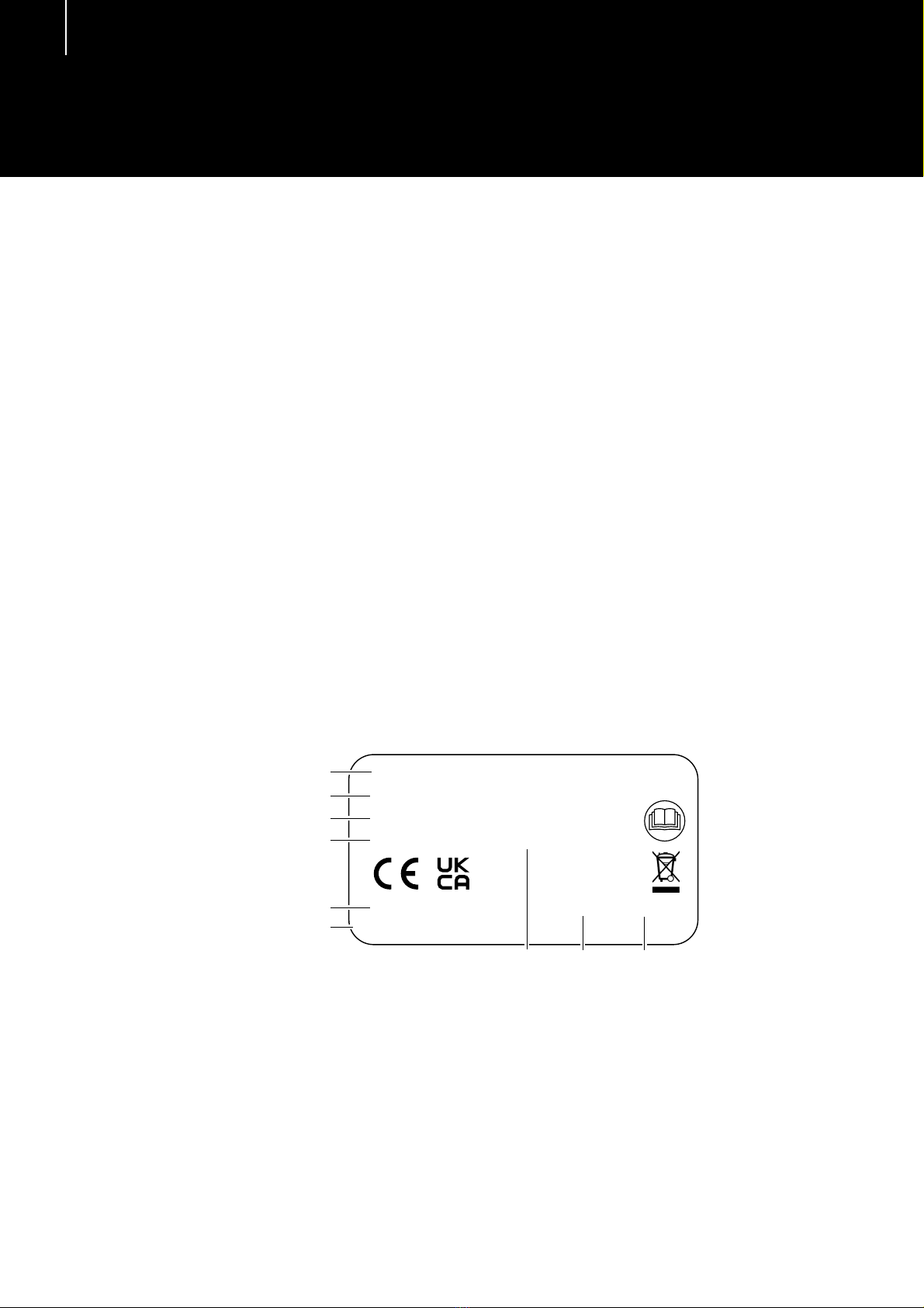
2.2 Nameplate ............................................................................................... EN-10
2.3 Scope of delivery................................................................................... EN-11
2.4 Technical data ........................................................................................ EN-12
2.5 Intended use........................................................................................... EN-13
3 Installation ........................................................................................................ EN-15
3.1 Specifications for the cabin............................................................... EN-15
3.1.1 Installation site ...................................................................... EN-16
3.1.2 Air inlets and outlets............................................................ EN-17
3.1.3 Temperature sensor............................................................. EN-18
3.1.4 Specifications for the control unit .................................. EN-18
3.2 Heater guard rail.................................................................................... EN-18
3.3 Installing the heater ............................................................................ EN-19
3.4 Connecting cable.................................................................................. EN-20
4 Electrical installation.................................................................................... EN-21
4.1 General instructions for electrical installation............................ EN-21
4.2 Connections............................................................................................ EN-21
4.2.1 Connecting to 400 V 3N ~.................................................. EN-22
4.2.2 Connecting to 230 V 1N ~.................................................. EN-24
4.2.3 Internal wiring........................................................................ EN-25
4.3 Establishing an electrical connection............................................ EN-26
4.4 Heating time limitation....................................................................... EN-26
5 Commissioning ............................................................................................... EN-27
5.1 Filling rock stores with stones ......................................................... EN-27
5.2 Starting the heater................................................................................ EN-28
5.3 Commissioning by remote control................................................. EN-29
5.4 Water splash............................................................................................ EN-29

EN-4 Installation and Operating Instructions - EOS Majesty
EN
6 Maintenance.....................................................................................................EN-30
6.1 Cleaning....................................................................................................EN-30
6.2 Sauna stones...........................................................................................EN-31
6.3 Changing the electrical connection ...............................................EN-32
6.4 Replacing the tubular heating elements......................................EN-35
6.5 Troubleshooting....................................................................................EN-39
7 General terms and conditions of service ...........................................EN-40
8 Disposal ..............................................................................................................EN-43

1
EOS Majesty - Installation and Operating Instructions EN-5
General safety instructions
1.1 Mounting and electrical installation
The installation instructions are intended for qualified personnel familiar
with the laws and regulations applicable to electrical installations at the
installation site. Observe the following general safety instructions during
mounting, configuration and commissioning of the product.
Risk to life and limb
and risk of fire
Risk to life and limb from electric shock and fire in the event of im-
proper or faulty electrical connection. This risk remains also after
completion of the installation work.
The electrical installation of the heater, relay boxes and other
electrical systems or equipment with a fixed mains connection
must only be performed by a trained electrician from an author-
ised electrical company.
Ensure compliance with the applicable standards and regula-
tions for electrical installation.
The system must be completely disconnected from the mains
supply before commencing installation and repair work.
The housing cover must only be removed by a qualified electri-
cian.
Fire hazard from
overheating
Insufficient ventilation can lead to device overheating and fire.
Install air inlets and outlets in the cabin.
Observe the cabin manufacturer’s safety and installation in-
structions.
Risk of fire due to
sauna stones
It is possible for hot stones or stone pieces to fall out of the rock
store.
The sauna heater may not be placed on a floor made of easily
flammable material (e.g. laminate or synthetic flooring). Ceram-
ic tiles are recommended as a flooring option.

EN-6 Installation and Operating Instructions - EOS Majesty
General safety instructions
EN
Risk of burns from
hot glass
Glass surfaces in the cabin become hot while the sauna is in oper-
ation.
When installing the cabin, ensure that the touchable glass sur-
faces on the outside of the cabin may reach a maximum tem-
perature of 76°C. Appropriate protection may need to be
installed if required.
Risk of burns from
hot unit
During operation, the sauna heater may become hot and, if
touched, could cause burns.
Maintain a safe distance.
Sauna cabin and
heater
The sauna cabin must be constructed with proper material and
built in a professional manner, and the heater must be suited for
the cabin.
Sauna heaters and control units may only be used in sauna cab-
ins made of suitable, low-resin and untreated material (e.g. Nor-
dic spruce).
Multiple heaters may be installed in one sauna if the heater out-
put can properly supply the cabin volume. In this case, depend-
ing on the position, an additional safety temperature limiter
must be installed for each additional heater.
The sauna heater is not designed to be installed or set up in an
alcove or under a bench or sloping roof unless the sauna heater
is specifically designed and approved for this type of installa-
tion.
Receptacles may not be installed inside the sauna cabin.
Each sauna cabin must have air inlets and outlets. The air inlets
and outlets may be installed from below or from behind the
sauna heater. The minimum dimensions of the air inlets and
outlets can be found here: 2.4 Technical data, EN-12,
3.1.1 Installation site, EN-16.
The air outlet is always installed in the lower part of the wall, di-
agonal to the sauna heater. The air inlets and outlets must not
be closed. Please observe the instructions provided by your
sauna cabin manufacturer.
Use one of the control units listed below to check and control
the sauna heater. This control unit is fixed to a suitable location
on the cabin's external wall, and the corresponding sensor
housings according to the installation instructions that accom-
pany the control units inside the sauna cabin.

EOS Majesty - Installation and Operating Instructions EN-7
General safety instructions
The cabin lighting must be safe for sauna cabin use and in-
stalled in such a way that it can be used safely in a sauna cabin.
Ensure that the heater is installed in compliance with the stand-
ards and legal norms valid in your country.
The cabin door must open outward and must not have a lock
that cannot be opened in the case of failure. We recommend
magnetic or spring locks.
1.2 Operator instruction
The operator of the sauna cabin must be instructed in the general safety
instructions during commissioning. The operator must be given a copy of
the operating instructions.
Risk of electric shock A risk to life and limb from electric shock and fire arises in the event
of improper repair work. This risk remains also after work is com-
pleted.
The housing cover must only be removed by a qualified electri-
cian.
Repairs and installations must only be performed by a trained
electrician.
The system must be disconnected and removed entirely from
the mains supply before commencing repair work.
Use only original spare parts from the manufacturer.
Fire hazard Objects placed on the heater or protective grilles can easily be ig-
nited and cause fires.
Attach the heater guard rail.
Do not place objects on the heater.
Fill the stone grate as directed.
Inspect the sauna cabin prior to each commissioning.
If you switch on the heater using pre-set timers or a remote con-
trol, attach a protective cover to the heater or install a suitable
safety system.
Health risks Spending time in a sauna cabin can lead to serious health risks or
even death for persons with health impairments.
Persons with health impairments who spend time in a sauna
must consult a doctor before entering a sauna cabin.

EN-8 Installation and Operating Instructions - EOS Majesty
General safety instructions
EN
Damage to health Excessive time spent in a heated sauna cabin can lead to overheat-
ing of the body (hyperthermia), which may cause serious health
problems and even death. Hyperthermia occurs when the core
temperature of the body exceeds the norm by a few degrees.
Symptoms of hyperthermia include fever, dizziness, lethargy,
sleepiness, and fainting. Side effects of hyperthermia include per-
ception disorders, inability to recognize the need to leave the
room, inability to identify imminent danger, harm to the foetus in
the case of pregnant women, inability to physically leave the
room, unconsciousness.
Alcohol, drugs, and medications increase the risk of hyperthermia.
Do not exceed the maximum recommended time in the sauna.
Leave the sauna cabin if your body responds abnormally to the
heat or if you do not feel well.
Avoid alcohol, drugs, and medications when you are using the
sauna.
Operation by
children or persons
with reduced mental
capacity
Children and persons with reduced mental capacity can put them-
selves at risk.
Children must be supervised to ensure they do not play with
the unit.
Children under 8 years of age should not operate the sauna
cabin.
The settings for the heating time must only be changed by chil-
dren under 8 years of age if they are supervised by an adult.
The sauna cabin must only be used by persons with reduced
mental capacity, or limited physical or sensory abilities under
supervision or if they have been previously instructed in its use
and understand the risks.
Children and persons who have not received proper instruction
must not clean or service the system.

EOS Majesty - Installation and Operating Instructions EN-9
General safety instructions
1.3 Safety levels
Safety instructions and important operating instructions are classified
according to ANSI Z535.6. Please familiarise yourself with the following
terms and symbols:
WARNING
Warning
Indicates a hazardous situation which, if not avoided, could result
in death or serious injury.
CAUTION
Caution
Indicates a hazardous situation which, if not avoided, could result
in minor or moderate injury.
NOTICE
Notice
Indicates a hazardous situation which, if not avoided, will result in
damage to the unit.
1.4 Standards and regulations
For an overview of the standards that were observed during design and
construction of the sauna heaters, please refer to the individual product’s
technical data sheet that can be downloaded from www.eos-sauna.com.
Local regulations also apply to the installation and operation of heating,
sauna, and steam room systems.

2
EN-10 Installation and Operating Instructions - EOS Majesty
Identification
EN
Identification
EOS Majesty is an electrically heated sauna heater for Finnish mode availa-
ble in a variety of output capacities.
2.1 Requirements for operation
The heater must be operated with one of the following control units:
Econ series
EmoTec series
EmoStyle series
EmoTouch series
EOS Compact series (without power extension unit [LSG])
The control unit is not included in the scope of delivery.
A power extension unit is required for the output capacity 10 kW.
2.2 Nameplate
A Name
B Model
C Item number
D Electrical connection
E Country of origin
F Manufacturer
G Heater output
H Manufacturing date
I Serial number
Elektro-Saunaofen
Type EOS Majesty
Art. Nr. 94 XXXX 00
400V 3N ~ 50 Hz XX kW
IPX4
Made in Germany 00001S-No. 41.22
EOS SAUNATECHNIK GmbH, Schneiderstriesch 1, 35759 Driedorf
H I
A
F
E
D
C
B
G

EOS Majesty - Installation and Operating Instructions EN-11
Identification
2.3 Scope of delivery
Check the delivery to ensure that all components were delivered and that
they are in proper working order. Contact your distributor if components
are missing or damaged. The heater must not be operated if components
are missing or damaged.
The following parts are included in the scope of delivery:
Accessories (optional)
*) It is essential that the unit is protected from being touched. We recom-
mend using the EOS heater guard rail.
A Majesty sauna heater D Connecting cable 8 m, pre-installed
B Sauna stones, classic,
50–100 mm, approx. 15 kg
E Installation and Operating Instructions
C Sauna stones made of quartz,
white, approx. 10 kg
Accessories (optional) Item number
EOS heater guard rail (to protect unit from being
touched)*
94.6972
Distributor for 1-phase connection 94.2689
Guard rail, abachi wood, with bracket 94.8052
Guard rail, made of walnut, with bracket 94.8053
Rail bracket, 6 pcs., for Majesty sauna heater 94.8055
Sauna stones, classic, 50–100 mm, approx. 15 kg 94.8054
Sauna stones made of quartz, white, approx. 10 kg 94.7698
E
A
D
C
B

EN-12 Installation and Operating Instructions - EOS Majesty
Identification
EN
2.4 Technical data
Electrical connection data
All line cross-section specifications are the minimum cross-sections for the
copper line. The sauna heater must be operated by a sauna control unit.
*) Only for the EOS Econ, EmoTec, EmoStyle, and EmoTouch control units.
Heater
output Supply voltage Connection mains –
control unit
Connection
control unit –
heater
6 kW
400 V 3N ~ 50 Hz 5 x 2.5 mm² 5 x 1.5 mm²8 kW
10 kW
Heater
output
Connection
mains – LSG
Connection
LSG – heater
Connection
control unit – LSG
6 kW - - -
8 kW
10 kW 5 x 2.5 mm² 5 x 1.5 mm² 4 x 1.5 mm²
Heater
output
Fuse protection for
control unit
Power extension
unit Leakage current
6 kW
3 x 16 A No Max. 0.75 mA per kW
heater output
8 kW
10 kW LSG 10*
Heater
output
Fuse protection for
LSG unit
6 kW -
8 kW
10 kW 3 x 16 A

EOS Majesty - Installation and Operating Instructions EN-13
Identification
Heater
2.5 Intended use
This heater is intended solely for the purpose of heating sauna cabins,
together with a suitable control unit.
EOS Majesty is suitable for commercial and private use.
The heater is not suitable for outdoor use.
It must be operated only inside buildings and may not be exposed to envi-
ronmental conditions such as extreme humidity and moisture or the possi-
ble formation of condensation or corrosive substances in the ambient air,
as well as other weather conditions.
Any use beyond this is considered improper use. Proper use also includes
compliance with operating, maintenance and servicing requirements.
The manufacturer is not responsible for unauthorised modifications and
damages resulting from these modifications; the person modifying the
equipment alone shall bear the associated risk.
Heater
output
Unit dimensions
HxWxD in cm For cabin volumes Minimum size of air
inlet and outlet
6 kW
80 x 42 x 37
7–8 m³ 35 x 4 cm
8 kW 8–12 m³ 35 x 5 cm
10 kW 9–14 m³ 35 x 6 cm
Heater
output
Weight without
stones
Stone filling –
weight Grain size
6 kW
36 kg Approx. 20 kg 50–100 mm8 kW
10 kW

EN-14 Installation and Operating Instructions - EOS Majesty
Identification
EN
Foreseeable misuse
The following are considered instances of foreseeable misuse:
The unit is operated without knowledge of or compliance with the
safety instructions.
Operating, service and maintenance requirements are not observed.
The unit is operated by children under 8 years of age.
The unit is operated by children 8 years of age or older, or persons with
reduced mental capacity who have not been thoroughly instructed in
its use.
The unit is operated without sauna stones or with a rock store that is not
filled as directed.
The heater output does not match the cabin volume.
The unit is operated with insufficient air supply or exhaust air.
General instructions
Please note that an optimal sauna climate can be achieved only if the
cabin with its air inlets and outlets, the sauna heater, and the control
unit are synchronized.
Observe the specifications and information provided by your sauna
retailer.
Please note that the highest temperatures in the cabin are always above
the sauna heater and that is where the temperature sensor and safety
temperature limiter should be mounted according to the installation
instructions for the control units.
The sauna heaters heat the sauna cabin with heated convection air.
Fresh air is drawn in through the air inlet. It is warmed and rises (convec-
tion) and is then circulated in the cabin. Some of the used air is pushed
out of the cabin through the cabin's air outlet. This creates a typical
sauna climate in your sauna.
Note that there is a drop in temperature from the ceiling to the floor of
the sauna cabin. Temperatures are measured and regulated based on
the ceiling values.Thermometers placed below the ceiling will therefore
display lower temperatures. When the max. temperature is set for the
area around the upper sauna bench, the bathing temperature is typi-
cally between 80°C and 90°C.
The first time the cabin is heated, you may notice a slight odour result-
ing from the evaporation of consumables used in the manufacturing
processes. Air out your cabin once it has been heated and before using
the sauna.

3
EOS Majesty - Installation and Operating Instructions EN-15
Installation
Installation
Prior to installation, air inlets and outlets must be installed in the cabin. It
may be necessary to mount additional fans in the inlets/outlets.
NOTICE
Damage due to incorrect mounting location
The heater is not suitable for outdoor use.
The heater must be operated only inside buildings and may not
be exposed to environmental conditions such as extreme hu-
midity and moisture or the possible formation of condensation
or corrosive substances in the ambient air, as well as other
weather conditions.
The heater is not designed to be installed or set up in an alcove
or under a bench or sloping roof.
3.1 Specifications for the cabin
The cabin must be planned and installed according to specifications before
the heater is installed. It must be ensured that the heater can be removed
from the cabin even after the cabin has been installed
The floor on which the heater stands must be level.
In general, it should be noted that the sauna heater must not be set on a
floor made of highly flammable material (laminate, flooring made of plastic
material, etc.). Ceramic tiles are recommended as a flooring option.
Electrical lines
All electrical installations laid inside the cabin must be suitable for silicone
cables and a temperature of at least 170°C.
All lines must be routed in such a way that they are well-protected, e.g. in a
cable duct.
EOS recommends laying all connecting cables through a bendable metal
tube connected to the protective conductor.

EN-16 Installation and Operating Instructions - EOS Majesty
Installation
EN
3.1.1 Installation site
The required cabin volume depends on the heater output.
See 2.4 Technical data, EN-12.
Ceiling height of at least 190 cm
Distance heater – cabin wall min. 8 cm
Distance heater – bench (lower than heater) min. 5 cm
Distance heater – bench (higher than heater) min. 8 cm
The clearance distance between the heater and flammable material
(wood wall, recliner bench, etc.) must be observed as shown below.
A heater guard rail may be placed around the upper edge of the heater.
It prevents accidental contact with hot parts of the heater.
Dimensions in the cabin
A Cabin ceiling
B Cabin wall
C Heater guard rail
D Heater
E Air inlet
42 cm
8 cm 5 cm
5 cm
8 cm
37 cm
min. 190 cm
80 cm
min. 8 cm
37 cm
min. 5 cm
A
B
E
C
D
C
BD

EOS Majesty - Installation and Operating Instructions EN-17
Installation
3.1.2 Air inlets and outlets
Air inlets and outlets must be installed in the cabin to ensure a sufficient air
flow in the cabin and to prevent the heater from overheating.
The required size of the air inlets and outlets depends on the heater out-
put; see 2.4 Technical data, EN-12.
WARNING
Fire hazard from overheating
The heater can overheat if the air supply is insufficient. There is a
risk of death due to fire.
Ensure that the air inlets and outlets provide sufficient ventila-
tion. Install a fan if necessary.
Commission the cabin only after all air inlets and outlets have
been opened.
If the heating process takes a long time, the underlying reason is that the
heater receives insufficient air. A minimum of 5 times the cabin volume of
air per hour must be exchanged.
If, despite compliance with dimensions, there is still not enough fresh air to
reach the heater, a fan must be installed at the air inlet outside of the cabin.
Air inlet
Depending on the location of the heater, the air inlet must be installed
below or behind the heater.
Heater is located in the middle of the cabin: air inlet from below
Heater is located in front of the cabin wall: air inlet from the side
Supply air from below (figure on the left) and from the side (figure on the right)
A Air inlet B Heater
A
BB
A
A

EN-18 Installation and Operating Instructions - EOS Majesty
Installation
EN
Air outlet
The air outlet must meet the following criteria:
Position: across from the heater
Height: 30–50 cm above the cabin floor
3.1.3 Temperature sensor
It is essential that the temperature sensor with the safety temperature lim-
iter (STB) is installed.
The temperature sensor must be installed where expected temperatures
are the highest, meaning above the heater.
The temperature sensor with the safety temperature limiter is not included
in the scope of delivery.
The temperature sensor connection is described in the instructions for the
control unit.
3.1.4 Specifications for the control unit
Observe the operating conditions for the control unit to ensure that the
sauna cabin's temperature control works properly.
The installation site must be selected accordingly. Specifications can be
found in the installation instructions for the control unit or in the instruc-
tions provided by the manufacturer of the control unit.
3.2 Heater guard rail
CAUTION
Risk of burns if heater is touched.
The outer casing of the heater may become hot and, if touched,
could cause burns.
It is essential that a heater guard rail is installed so that the unit
is protected from being touched.
A heater guard rail may be placed around the upper edge of the heater. It
prevents accidental contact with hot parts of the heater.
You can purchase a suitable heater guard rail from the sauna heater manu-
facturer. See Accessories (optional), EN-11

EOS Majesty - Installation and Operating Instructions EN-19
Installation
3.3 Installing the heater
The heater is supplied mounted and packaged on a pallet. Once the cabin
is prepared, the heater is placed on a pre-defined installation site. Two peo-
ple should always transport the heater.
Unpacking the heater
1Remove the heater packaging.
Leave the heater on the pallet.
2Remove all transport locks and protective films in the heater.
Setting up the heater
1Move the pallet with the heater as close to the pre-defined installation
site as possible.
Do not place the heater too close to a wall prior to commissioning. It
must still be possible to reach the terminal box at the rear of the heat-
er.
2Lift the heater from the pallet and move it to the pre-defined installation
site.

EN-20 Installation and Operating Instructions - EOS Majesty
Installation
EN
3.4 Connecting cable
The heater is connected to the control unit or to the power extension unit
and the control unit via a connecting cable. Observe the regulations of the
local power supply company (EVU) and the Association for Electrical, Elec-
tronic & Information Technologies (VDE). Install the cable in such a way
that it is protected from damage. This means that the cable must be routed
under a suitable protective cover (e.g. in a cable duct or empty conduits).
See the connection diagram: Connections, EN-21.
Concealed connecting cable (optional)
The connecting cable can be laid so it is concealed underneath the cabin
floor with a suitable cover and fed through the heater base. To conceal the
connection of the connecting cable, an opening in the cabin floor under
the heater base via a cable duct is required.
Drilling template for concealed connecting cable
Lay the connecting cable along the heater base from the cabin to the con-
trol unit or power extension unit.
A Hole for connecting cable B Heater base
A Rear of heater
B Cable feed opening
C Connecting cable
37 cm
==
42 cm
= =
A
B
A
B
C
Table of contents
Other EOS Heater manuals

EOS
EOS 46.U Planning guide

EOS
EOS Vitae Protect+ Planning guide

EOS
EOS Zeus S User manual

EOS
EOS Herkules S60 Planning guide

EOS
EOS Herkules XL S120 User manual

EOS
EOS Mythos S45 User manual

EOS
EOS Edge Control User manual

EOS
EOS Vitae protect+ Planning guide

EOS
EOS 38.AS Installation guide

EOS
EOS 94 3742 Installation guide
Popular Heater manuals by other brands

Fired Up Corporation
Fired Up Corporation NDT10-22B1 instruction manual

Burda
Burda SMART IP24 Instructions for use

Global
Global Naypia HE GPHL**RN Installation, maintenance & user instructions

Monessen Hearth
Monessen Hearth Lyric Series Installation & owner's manual

Taurus Alpatec
Taurus Alpatec VILNA 600 P manual

PVG
PVG R 22X C - REV 3-07 operating manual