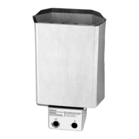
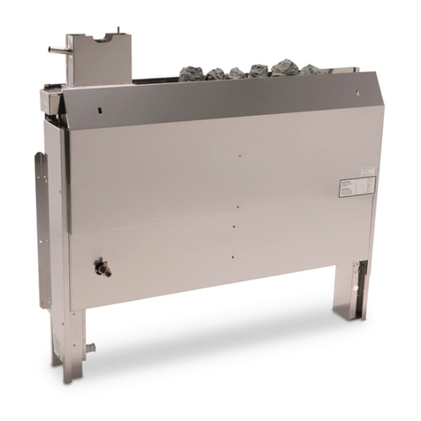
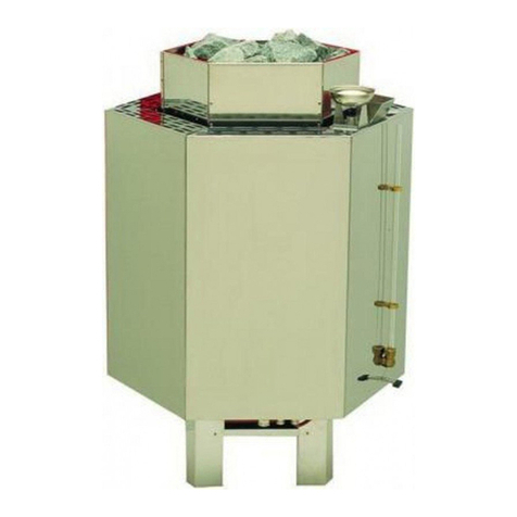
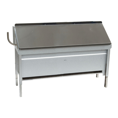
EOS Herkules XL S120 Planning guide

1
D
MADE IN GERMANY
Herkules XL S120 vapor
IPx4
Herkules XL S120
Herkules XL S120 vapor
Druck Nr. 29343553en /22.10
GB Assembly and operating instruction

2GB
English
Table of Contents
Intended use ...........................................................................................................3
General notes .........................................................................................................3
Important notes.......................................................................................................4
Electrical connection ..............................................................................................5
Installation...............................................................................................................7
Minimum clearances .........................................................................................7
Positioning of sensor.........................................................................................7
Installation...............................................................................................................8
Electrical connection.............................................................................................10
Herkules XL S120 18 kW ................................................................................10
Herkules XL S120 vapor 18 kW ......................................................................11
Herkules XL S120 24 kW ................................................................................12
Herkules XL S120 vapor 24 kW ......................................................................13
Herkules XL S120 30 kW ...............................................................................14
Herkules XL S120 vapor 30 kW ......................................................................15
The water connection ...........................................................................................16
De-scaling of the vaporizer ...................................................................................16
Assembly of the protective cover on the sauna heater ...................................17
Finnish sauna operation .......................................................................................18
Operation with vaporizer.......................................................................................18
Sauna stones........................................................................................................19
Maintenance and care ..........................................................................................19
Service Address:...................................................................................................21
Guarantee.............................................................................................................21
Handling procedures for return shipments (RMA) - Details for all returns !.......22

3
GB
Dear Customer,
You have purchased a high quality technical
system which will provide you with many ye-
ars of enjoyable sauna bathing. This sauna
heating system was constructed in accor-
dance with state-of-the-art European safety
standards, inspected and manufactured in
accordance with the Quality Standard DIN
EN ISO 9001:2000.
This detailed installation and user‘s guide was
created for your information. Please note
especially the important information and the
data dealing with the electrical connection.
We wish you a richly invigorating and resto-
rative sauna bathing experience.
First of all, check whether the sauna system
has arrived at your site undamaged. Register
transport damage claims immediately with
the delivering transport company or please
consult the supplier who provided the equip-
ment to you.
General notes
Please note that an optimal sauna climate
can be reached only when the cabin, with
its air intake and exhaust, the sauna heating
unit and the control unit have been tuned for
compatibility with one another.
Please note all data and information provided
by your sauna supplier.
The sauna heating units warm your sauna
cabin through means of heated convection
currents. To this end, fresh air from the air
intake vent is drawn in, rises upon warming
(convection) and is then circulated through
the cabin. A part of the used air is pushed out
through the exhaust vent in the cabin. This is
the means by which the typical sauna climate
develops, reaching characteristic temperatu-
res of about 110° C directly under the ceiling
of your sauna, which fall off to about 30-40°C
in the floor area due to the temperature gra-
dient in the sauna cabin. Therefore, it is not
unusual when, for example, temperatures of
110°C prevail in the area of the temperature
sensor over the oven, while the thermometer,
which is installed 20-25 cm under the cabin
ceiling on the sauna wall, registers only 85°
C. With a temperature setting at maximum,
the mean bathing temperature lies between
80°C and 90°C in the area of the upper rec-
liner bench.
Please note that the highest temperature va-
lues in the cabin always develop in the area
above the sauna heating unit and that the
temperature sensor and safety limiter must
be installed in this area in accordance with
the control unit installation guide.
At the initial heating, you may notice a slight
odor arising from evaporation of substances
from the manufacturing process. Air out your
cabin after this cycle before you begin with
the sauna bath
Intended use
This sauna heater is exclusively designed
for the heating of sauna cabins, in connec-
tion with an appropriate control unit.
Any use apart from the defined application
shall be regarded as non-intended use. Ad-
herence to the conventional operating, main-
tenance and servicing conditions is also part
of the intended use.
The manufacturer cannot be made respon-
sible for deviating alterations undertaken on
the authority of the user and any consequen-
tial damage. The risk for such measures
shall be borne solely by the person carrying
out the alterations and causing the damage.
Sauna heaters, with the exception of tho-
se used for household purposes, must be
equipped with a safety device vis-à-vis the
cover per DIN EN 60335-2-53.
As suitable measure, and depending on the
sauna heater, a rocker switch Type I or Type
II may be installed above the heater.
(The rocker switch is not included in the de-
livery scope of the sauna heater.)
For installation and electrical connection of
the rocker switch follow the installation in-
structions supplied with this part.
4GB
air intake and exhaust vents must not be
closed. Please observe the information
provided by your sauna cabin supplier.
• For the adjustment and control of the sau-
na heating unit, one of the control units
mentioned later must be used. This con-
trol unit must be attached to a suitable lo-
cation on the outer wall of the cabin, the
associated sensor housings in the interior
of the sauna cabin in accordance with the
installation guide which accompanies the
control units.
• Caution: Covering and improperly
filled stone receptacles present a fire
hazard.
• Make certain that no objects have
been placed on the sauna heating
unit before each start-up.
• Caution: High temperatures on the
heating unit during operation can
cause burns on contact.
• The sauna heating unit is not intended for
installation or placement in a niche under
the bench or under a roof slope.
• Do not start up operation of the sauna he-
ating unit with air intake vents closed.
• The cabin lighting with corresponding
mounting must be of a type that it is splash-
proof and able to withstand a surrounding
temperature of 140° C. Therefore, only
a VDE-certified sauna lamp of 40 W ma-
ximum may be installed for use with the
sauna oven.
• The sauna system (sauna heating
unit, control unit and lighting etc.)
may be hard-wired to the power sour-
ce only by a locally certified electrician.
All connecting lines laid on the inside of
the cabin must be made of silicone and
be able to withstand a surrounding tem-
perature of at least 170°C. If single-wired
cables are used as connecting lines, they
must be protected by flexible metal tubing.
The minimum diameter of the connecting
line and the suitable cabin size in proporti-
on to the power supply capacity are listed
Important notes
If assembled incorrectly, the sys-
tem will present a fire hazard.
Please read this installation guide tho-
roughly. It is especially important to con-
sider applicable dimensions and observe
the following instructions:
• This device has not been designed for
being used by persons (including children)
that are physically or mentally handicap-
ped or have sensory disabilities. Moreover,
it is not allowed to use this device without
sufficient experience and/or knowledge,
unless these persons will be supervised
by persons responsible for their security
or in case they have been instructed how
to use this device.
• Children are to be supervised in order to
make sure that they do not play with this
device.
• The installation and connection of the
sauna heating unit, control unit and
other electrical equipment must be ac-
complished only by an expert. In this re-
gard it is especially important to meet the
required safety precautions in accordance
with VDE 0100 v. §49 DA/6 and VDE 0100
part 703/2006-2.
• The sauna heating and control units may
be installed only in sauna cabins made of
suitable, low resin and untreated material
(for example: Nordic pine)
• Only a sauna oven with the appropriate
heating capacity may be installed in the
sauna cabin (see Table 2).
• There should always be a provision for air
intake and exhaust vents in every sauna
cabin. The air intake vents must always
be aligned behind the sauna heating unit,
ca. 5 to 10 cm above the floor. Please use
the minimum dimensions of the air intake
and exhaust vents listed in Table 1.
• The exhaust vents must always be placed
towards the sauna heating unit diagonally
in the rear sauna wall, lower area. The

5
GB
in the table.
• During the installation of the sauna hea-
ting unit, make certain that the vertical
clearance between the upper edge of the
sauna heating unit and the sauna ceiling
is sufficient . The horizontal (lateral) clea-
rance between the sauna heating unit and
the cabin wall is provided in the dimension
diagram of the respective sauna heating
unit. The required distance between the
lower edge of the sauna heating unit and
the floor is also provided by the dimension
diagram. In case of floor-standing ovens,
the distance is determined by the base.
• Fundamentally, it is important to make
sure that the sauna heating unit is not
placed on a floor that consists of an easily
flammable material (wood, synthetic floo-
ring or similar material). Ceramic tiles or
similar materials are practical in the area
of the sauna.
• Underfloor heating in a sauna leads to in-
creased surface temperature of the floor.
• The distance between the oven safety
grid or recliner bench and other flamma-
ble materials and the sauna heating unit
are provided in the dimensional data of the
respective sauna heating unit. The safety
grid height must be approximately equal
to the frontal height of the sauna heating
unit.
• By cleaning of parts with sharp edges
or corners the appropriate personal
protection measures against potential in-
juries should be taken.
Electrical connection
Your electrician will be able to accomplish
this work without further explanation in ac-
cordance with the provided wiring schematic
and with the help of the circuit diagram
mounted inside the respective control unit.
Be sure to note, however, that live wires
should not be visibly laid onto the inner cabin
walls due to safety considerations. For this
reason, the wall element with the air intake
vent is already equipped with cable conduits
in most sauna cabins
Should there be no cable conduits in your
cabin, drill an hole in the cabin wall imme-
diately adjacent to the sauna heating unit
where the cable projects from the sauna he-
ating unit and pull the cable through this hole
towards the exterior and then to the control
unit. The cable as well as all other connec-
ting lines (supply wire to the power source
and to the cabin lighting) on the outside wall
of the cabin should also be protected from
damage, for ex. by installation in cable con-
duits or by covering with wooden skirting
strips.
Attention!
Dear customer,
according to the valid regulations, the
electrical connection of the sauna hea-
ter and the control box has to be carried
out through the specialist of an authori-
zed electric shop.
We would like to mention to the fact
that in case of a warrenty claim, you
are kindly requested to present a copy
of the invoice of the executive electric
shop.

6GB
The scope of delivery should include:
1 sauna heater
8 sets of sauna rocks supplied in fabric
bags
1 aroma bowl, 1 stand for the aroma bowl
1 accessory bag containing the warning
plate and 2 bolts (4.2 x 9.5)
Technical data
Voltage: 400 V AC 3N 50 Hz
Power consumption: 18,0 24,0 or 30,0 kW
according to model
Vaporizer: only Herkules vapor XL
3 /4 kW
Height: 850 mm
Width:960 mm
Depth: 530 mm
Filling capacity for stones: 120 kg
Weight: 85 kg (without packaging)
Stray current: max. 0,75 mA per kW hea-
ting capacity
Sauna oven for use in commercial saunas
The warning sticker is to be fix viewable
in the near of the sauna heater.
Capacity
acc. DIN Vaporicer Electrical.
Connection
Fuse control
unit in A
Fuse LSG
in A
Connecting
cable main
- control
unit in mm²
Connecting
cable main -
LSG in mm²
Connecting
cable control
unit - heater
in mm²
Connecting
cable LSG
- heater
in mm²
Connecting
cable control
unit - LSG
in mm²
18 kW 3 kW
3N AC
50 Hz
400 V
3 x 16 3 x 16 5 x 2,5 5 x 2,5 5 x 1,5
4 x 1,5 5 x 1,5 4 x 1,5
24 kW
4 kW
3 x 16 3 x 35 5 x 2,5 5 x 6 5 x1,5
3 x 1,5
5 x 4
4 x 2,5 5 x 1,5
30 kW 1 x 16 3 x 63 3 x 1,5 5 x 16 3 x 1,5 2 St. 5 x 4
1 St. 4 x 2,5 6 x 1,5
All cross sections of a line are minimum diameters in mm² (Copper line)
Herkules XL S120 vapor
Capacity
acc. DIN
Electrical.
Connection
Fuse control
unit in A
Fuse LSG
in A
Connecting
cable main
- control
unit in mm²
Connecting
cable main -
LSG in mm²
Connecting
cable control
unit - heater
in mm²
Connecting
cable LSG
- heater
in mm²
Connecting
cable control
unit - LSG
in mm²
18 kW
3N AC
50 Hz
400 V
3 x 16
3 x 16
5 x 2,5
5 x 2,5
5 x 1,5
5 x 1,5
4 x 1,524 kW 3 x 35 5 x 6 5 x 4
30 kW 1 x 16 3 x 63 3 x 1,5 5 x 16 2 St. 5 x 4
All cross sections of a line are minimum diameters in mm² (Copper line)
Herkules XL S120
Capacity
acc. DIN
Installation
dimensions
H/W/D cm
For cabin
size
Minimum
dimensions of
air intake and
exhaust vents
Weight
without
stones
without
package
Stone filling Power switch
gear needed
For operation with
control units
18 kW
85 x 96 x 53
24 - 35 m³ 50 x 6 cm
ca. 85 kg 2 x 60 kg
EMOTEC L09 EMOTEC DC 9000
EMOTEC DC 9000 DB/DL/DLF
EMOTEC HCS 9003
EMOTEC HCS 9003 DB/DL/DLF
EmoTouch II PB/AF/GF
24 kW 35 - 45 m³ 50 x 8 cm LSG 18
30 kW 45 - 65 m³ 50 x 10 cm LSG 36
Capacity
acc. DIN Vaporicer
Installation
dimensions
H/W/D cm
For cabin
size
Minimum
dimensions of
air intake and
exhaust vents
Weight
without
stones
without
package
Stone filling Power switch
gear needed
For operation with
control units
18 kW 3 kW
85 x 96 x 53
24 - 35 m³ 50 x 6 cm
ca. 85 kg 2 x 60 kg
EMOTEC L09
EMOTEC HCS 9003
EMOTEC HCS 9003 DB/DL/DLF
EmoTouch II PB/AF/GF
24 kW 4 kW 35 - 45 m³ 50 x 8 cm LSG 18H
30 kW 45 - 65 m³ 50 x 10 cm LSG 36H

7
GB
Installation
Caution: remove the side panes
for transporting without a euro
pallet!!!
(It is not possible to carry the sauna heater
by lifting and holding the side panes.)
Loosen the 4 visible screws on each side
panel.
Following the alignment of the sauna heater,
remove any remaining protective film and re-
mount the side panes.
Adjustment and displacement of the sauna
heater when it is filled with rocks is not pos-
sible.
Minimum clearances
96 cm
8 cm 8 cm
8 cm 8 cm
53 cm
Fig. 1
• The minimum height of the sauna cabin
must be 2.10 m on the inside.
• During the installation of the sauna heater
ensure that the vertical clearance between
the top edge of the sauna heater and the
roof of the sauna cabin is at least 125 cm
and that the horizontal (lateral) clearance
between the heater and the cabin wall is
at least 8 cm.
Positioning of sensor
8 cm
8 cm
min. 125 cm
ca.51 cm
ca. 85 cm
Cabin wall
Cabin roof
R o c k
basket in-
clined to
the wall
Contradictory to the specifications concer-
ning the mounting of the sensor of your
sauna control unit, the heater sensor is not
mounted centrically above the sauna heater
but, as shown in the diagram, above the rock
basket inclined towards the side wall of the
cabin.
• The clearance between inflammable mate-
rials and the sauna heater must be at least
8 cm.
• The wooden rail is no substitute for a safe-
ty barrier for protection against accidental
contact. A suitable safety barrier should be
provided by the manufacturer of the cabin
according to the individual situation of in-
stallation
When used for commercial purposes, the
sauna heater may only be used in combi-
nation with the rocker switch Type II Art. No.
94.4424.

8GB
Installation
Water level
control for va-
porizer
Terminal box
for vaporizer
Terminal box
for heating
coils
Screw the connection hose of the vapori-
zing bowl to the bottom fitting of the water
level control
(1)
(2)
(3)
A plunger (1) opens or closes the volve (2),
so that you can be sure your container is al-
ways full.
The levers (3) serves fot the adjustment of
the closing strength. Turn to the left indicates
a greater closing strength.
(only Herkules XL S120 vapor)
(only Herkules
XL S120 vapor)
(only Herkules
XL S120 vapor)

9
GB
1,0 kW
1,0 kW
1,0 kW
1,0 kW
1,0 kW
1,0 kW
1,0 kW
1,0 kW
1,0 kW
1,0 kW
1,0 kW
3
1,0 kW
1,0 kW
1,0 kW
1,0 kW
1,0 kW
1,0 kW
2 1
1,0 kW
5 4 3 2 1
N V
W
U
zum Steuergerät 9 kW
to control unit
zum Leistungsschaltgerät 9 kW
to power control unit
5 466
2 2 2
N
W1 1
V
1
U
18 kW
1,33 kW
1,33 kW
1,33 kW
3 2 1
1,33 kW
1,33 kW
1,33 kW
1,33 kW
1,33 kW
1,33 kW
1,33 kW
1,33 kW
1,33 kW
1,33 kW
1,33 kW
1,33 kW
1,33 kW
1,33 kW
1,33 kW
5 4 3 2 1
N V
W
U
5 466
2 2 2
N
W1 1
V
1
U
24 kW
zum Steuergerät 8 kW
to control unit
zum Leistungsschaltgerät 16 kW
to power control unit
zum Leistungs-
schaltgerät 36 kW
to power control unit
1,66 kW
1,66 kW
1,66 kW
1,66 kW
1,66 kW
1,66 kW
1,66 kW
1,66 kW
1,66 kW
1,66 kW
1,66 kW
3
1,66 kW
1,66 kW
1,66 kW
1,66 kW
1,66 kW
1,66 kW
2 1
1,66 kW
30 kW
5 4 3 2 1
N V
W
U
5 466
2 2 2
N
W1 1
V
1
U
15 kW
15 kW
5 x 4 2
5 x 4 2
Heizstab-Verdampfer
heating element water
bl
max. 1,5 kW
max. 1,5 kW
buzzer
Summer
Thermal
cut-out
Thermostat-
Verdampfer
bl
Anschluß Steuerung
to control unit
Wm
N
PE
Wb
N
L
Heizstab-Verdampfer
heating element water
bl
max. 2 kW
max. 2 kW
buzzer
Summer
Thermal
cut-out
Thermostat-
Verdampfer
bl
Anschluß
Leistungsschaltgerät
Anschluß
Steuerung
to power control unitto control unit
Wm
N
PE
Wb
N
LV2
LV1
only
Herkules XL
S120 vapor

10 GB
Electrical connection
L1 L2 L3 N
Sensor
Limiter
S1
Saunasteuergerät
control unit
U V W WB WM N
400 V AC 3N
4 3 2 1
Sensor
4 3 2 1 U V W N L1 L2 L3 N
S1 V N
400 V AC 3N
ECON / EMOTEC
LSG
5 5
5
4
5
4
Saunasteuergerät
control unit
ECON / EMOTEC
Netz / Main
Herkules XL S120 18 kW
LSG 9
Caution! Always include the
neutral line N in the connec-
tion

11
GB
L1 L2 L3 N
Sensor
Limiter
S1
Saunasteuergerät
control unit
U V W WB WM N
400 V AC 3N
4 3 2 1
Sensor
WB WM N
max. 3 kW
4 3 2 1 U V W N L1 L2 L3 N
S1 V N
400 V AC 3N
ECON / EMOTEC
LSG
5 5
5
4
5
4
Saunasteuergerät
control unit
ECON / EMOTEC 3
optional
4
Netz / Main
Herkules XL S120 vapor 18 kW
LSG 9
Caution! Always include the
neutral line N in the connec-
tion

12 GB
LSG
55
5
4
5
4
Saunasteuergerät
control unit
ECON / EMOTEC
Netz / Main
L1 L2 L3 N
Sensor
Limiter
S1
Saunasteuergerät
control unit
U V W WB WM N
400 V AC 3N
4 3 2 1
Sensor
4 3 2 1 U V W N L1 L2 L3 N
S1 V N
400 V AC 3N
ECON / EMOTEC
Herkules XL S120 24 kW Caution! Always include the
neutral line N in the connec-
tion
LSG 18

13
GB
LSG 18 H
34
55
5
5
5
4
Saunasteuergerät
control unit
ECON / EMOTEC 3
optional
Netz / Main
L1 L2 L3 N
Sensor
Limiter
S1
Saunasteuergerät
control unit
U V W Wb Wm N
400 V AC 3N
4 3 2 1
Sensor
LV2Wb N Wm LV1 4 3 2 1 U V W N L1 L2 L3 N
S1 V N
400 V AC 3N
Wm N LV1LV2N
LSG 18 H
ECON / EMOTEC
Herkules XL S120 vapor 24 kW Caution! Always include the
neutral line N in the connec-
tion

14 GB
L1 L2 L3 N
Sensor
Limiter
S1
Saunasteuergerät
control unit
U V W WB WM N
230 V 50Hz
4 3 2 1
Sensor
4 3 2 1 U1 V1 W1 N L1 L2 L3 N
S1 U V N
400 V AC 3N
U V W N
LSG 36
ECON / EMOTEC
LSG 36
3 5
5
4
5
4
Saunasteuergerät
control unit
ECON / EMOTEC
Netz / Main
Herkules XL S120 30 kW Caution! Always include the
neutral line N in the connec-
tion

15
GB
L1 L2 L3 N
Sensor
Limiter
S1
Saunasteuergerät
control unit
U V W Wb Wm N
230 V AC N
4 3 2 1
Sensor
WbWm LV1LV2 N 4 3 2 1 U V W N L1 L2 L3 N
S1 U V N
400 V AC 3N
Wm N LV1LV2N
U1 V1 W1 N
LSG 36 H
ECON / EMOTEC
LSG 36 H
34
3 5
5
6
5
4
Saunasteuergerät
control unit
ECON / EMOTEC 3
optional
Netz / Main
Herkules XL S120 vapor 30 kW Caution! Always include the
neutral line N in the connec-
tion

16 GB
Attention!
At all cleaning- and maintenance
jobs, by changing of parties or accesso-
ries
and by cancelling troubles, the unit has
to be disconnected from the mesh.
Please note: Between fixed water
system and fixed water connection
a shut-off cock must be installed.
In case the fixed water connection will not
be used for any length of time, the shut-off
cock is to be closed.
The water regulation is on the back site of
the heating unit.
On the right site of the bottle is a 3/8“ nipp-
le. On this nipple you could add your feed
line individual on the attach water mesh.
3/8“ connec-tion nipple for fixed
connection on site.
If you water hard grade is II - IV we recom-
mend to install a descale system.
Consult your water utility company to determine
the hardness level of your water. In areas with
hardness level 1 (1-7 German hardness levels),
the system generally works without problems
and must be de-scaled only when necessary.
De-scaling of the vaporizer
Should your water lie within the hardness
levels 2-4, the vaporizer must be de-scaled
from time to time (in accordance with the
hardness level).
To this end, add the de-scaling product for
household appliances to the water in the va-
porizer in accordance with manufacturer´s
instructions. Bring the water-and-de-sca-
ling product mixture to a boil for about 10
minutes and allow to cool. After cooling,
drain the mixture from the vaporizer and
rinse at least twice with clear water. Note
also the instructions given by the de-scaling
product manufacturer.
The water drain is positioned behind the
front panel. To reach the drain, first remove
the vaporizer bowl together with the stand.
Unscrew the bolts on the rear side of the
central panel and slide the panel upwards
The water connection
(only Herkules XL S120 vapor)
The sauna heater must be connected with
the water main supply at the installation
site
Important Notes:The regulations of
EN 1717 and/or DIN 1988 Part 4
must be attended. Appropriate
measures must be taken that prevent the
water from running back into the drinking
water pipeline. For this, especially pipe iso-
lators or system isolators are appropriate.
If necessary, ask your drinking water supp-
ly company or your local sanitary expert.
Attention: Maximum opera-
ting pressure 6 bar

17
GB
55 12
je 4x Ø 3,5
12
55
620
45,5
Z
45,5
Z
45,5
620
1.
2.
94 4711
A
A
Assembly of the protective cover on the sauna heater
4 plate screws for
each
Control cable for
rocker switch
Lay the control cable for the rocker switch and heater
supply with a minimum clearance of 30 mm.
All plate screws for suspension of the heater protector.
All metric screws: for mounting the rocker switch
All dimensions provided in mm.

18 GB
Caution concerning control units
with post-heating phase. Never
leave the herbal bag in the herbal bowl
during the post-heating phase after a
moist steam session. These dry out
rapidly in this case and a present a fire
hazard!
Attention: Risk of scalding at the
steam outlet. Essences and herbs
are to be placed in the herb dish only.
Attention: Infuse the infuse water-
only in the area of the stones and not
in the area of the screen.
At this kind of sauna bath never
place herbs or similar in the herb
bowl. Fire risk!
Abb. 10
Finnish sauna operation
For this type of operation, the vaporizer is not
used. Itisveryimportantto makesurethatno
herbs or essences are present in the herbal
bowl,becausethese couldigniteduetoover-
heating. Addessencesorinfusionagentstothe
infusion water only according to manufacturer‘s
instructions.
At the end of the sauna session when you are
ready for the infusion, do not pour the water over
the stones with the ladle too quickly. This allows
full evaporation of the water and thereby the full
effect of the infusion to be reached.
Herb dish
Never put more infuse mediums or
essential oils into the infuse water than
denoted. Never apply alcohol or neat
concentrates. Attention! Fire risk!
Operation with vaporizer
(only Herkules XL S120 vapor)
The control of the vaporizer is managed
by the control unit. Either you receive a
humidity value which is regulated by a vari-
ance comparison at the sensor or which is
determined through a timing cycle.
Please note that the relative humidity varies
greatlyduetothevaryingtemperaturedistribution
inthe cabin. Thereadingsof thehygrometerand
thereadingsatthecontrolunitcanforthatreason
be very different.
Before the sauna bath, please control, if
the stop valve of the attach water mesh is
opened.
Never add essences, volatile oils or herbs
to the water; instead add these to the
herbal bowl on the lid of the vaporizer.
By adding essences or any other addi-
tives for air humidity, a health hazard
cannot be removed. It is advised not to
use those additives apart from the re-
commended ones by the manufacturer
of the oven.
If additives are put in the water, this generally
leads to a foamy boiling over of the water.
In this case the water must be drained and
the interior of the cold reservoir washed out
with a cloth soaked in alcohol or mineral
spirits. Even small remainders of essences
on the vaporizer wall will change the natural
molecular structure of the water.

19
GB
Please be sure to note!
Do not stack the stones in layers; stack them
loosely instead, leaving as many spaces as
possible to allow the rising hot air to circu-
late.
Remove stones from the sauna heater
only when they are cooled off.
Sauna stones
The sauna stone is a natural product. Check
the sauna stones at regular intervals. Strong
infusion concentrates especially can wea-
ken the sauna stones and cause them to
disintegrate over time. Consult your sauna
supplier if necessary.
Thoroughly clean the sauna stones provided
under running water and then place them in
the stone receptacle so that the convection
air current can circulate easily between the
stones (Illust. 9 + 10).
The number of stones is adequate to crea-
te a steam burst, vaporizing about 10 cl of
water per m³ cabin volume. Always wait 10
minutes after infusion before repeating the
infusion. Only then are the sauna stones
sufficiently hot.
Never add more infusion agents or volatile
oils than instructed on the packaging. Never
use alcohol or undiluted concentrates. Cau-
tion! Fire hazard!
Maintenance and care
All sauna heating units are made of low-
corrosion material. Still, to enjoy your sau-
na heating unit for a long time, you should
maintain and care for the unit. To this end,
always make sure that the vents and re-
flection plating in the area of air intake are
free of objects. These can easily become
clogged with fuzz and dust when drawing in
fresh air. This reduces the air convection in
the sauna heating unit and can be a cause
of unacceptable temperatures.
Clean or de-scale the units when needed.
Refer to your sauna supplier or directly to
the manufacturing plant in case of defects or
signs of wear and tear.
Only use original manufacturer‘s replace-
ment parts, which can be obtained from your
supplier or directly from the manufacturer.
If you do not use your sauna for a signifi-
cant period of time, always check before
next use that cloths, cleansers or other
objects have not been placed on the sau-
na heating unit or the vaporizer before
turning them on.

20 GB
For the installation of sauna heaters,
please pay attention to the DIN VDE 0100
part 703 !
This standard makes the following statement
valid in your newest expenditure, since Febru-
ary 2006, paragraph 703.412.05; Quotation:
The additional must be planned for all electric cir-
cuits of the Sauna by one or more fault current
protection device (RCDs) with a calculation diffe-
rence stream not more largely than 30 mA, exclu-
ded of it is Saunaheating.
The EN 60335-1 DIN VDE 0700 part 1 of Janu-
ary 2001 states the following in paragraph 13;
quote:
The leakage current may not exceed the fol-
lowing values during operation:
- for stationary heaters of protection class I 0,75
mA; or 0,75 mA each kW input of the appliance,
depending on the higher value, at a maximum va-
lue of 5 mA.
If the appliance is equipped with a protective
device for leakage current (ELCB), please pay
attention to the fact that no other electrical
units will be protected by this ELCB.
Under current manufacturing methods, it is
not yet possible to produce tubular heating
elements for sauna heaters which do not at-
tract moisture on each end from the surroun-
ding air. It is also possible that moisture from
the surrounding air has been concentrated in
the magnesium-oxide filling in the heating ele-
ments during transport or storage and is now
causing the ELCB to be triggered.
In this case, the oven must be heated up under
supervision of an expert, during which the PE
conductor is not connected. After about 10
minutes, when moisture has evaporated from
the heating elements , the oven must be recon-
nected to the PE conductor!
If the sauna heater is not in use for a signifi-
cant period of time, we recommend running it
every 6 weeks, so as to avoid moisture con-
centrating in the heating elements.
Therefore, should the ELCB be triggered duri-
ng start-up, the electrical installation must be
checked.
Installation of the sauna heater and control
unit may be undertaken only by an authorized
electrician. Without documentation of such in-
stallation, a warranty is fundamentally invalid.
Other manuals for Herkules XL S120
3
This manual suits for next models
1
Table of contents
Other EOS Heater manuals
Popular Heater manuals by other brands

Termozeta
Termozeta TZR53G instruction manual

Coopers of Stortford
Coopers of Stortford 10921 Instructions for use

AERMEC
AERMEC OmniaRadiant user manual

HouseWarmer
HouseWarmer HW500GW0XX1N-1 Installation instructions and owner's manual

Kruger
Kruger LOKI 55 instruction manual

Smart+ Products
Smart+ Products SPP-1000-4WC instructions