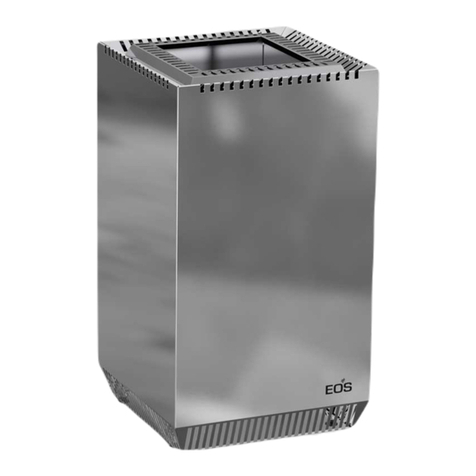
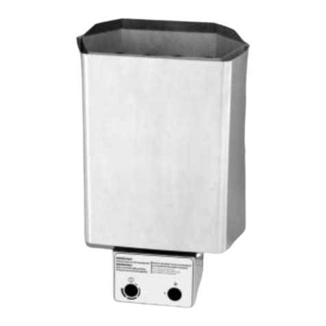
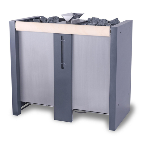
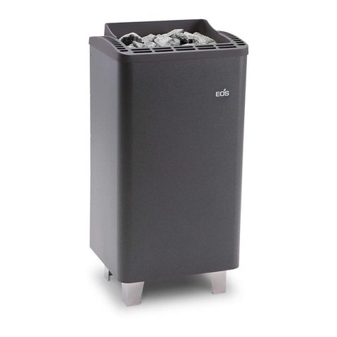
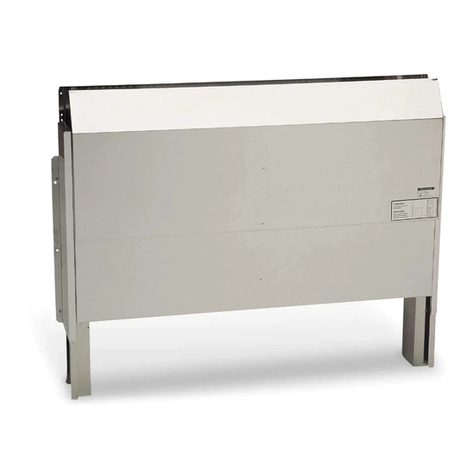
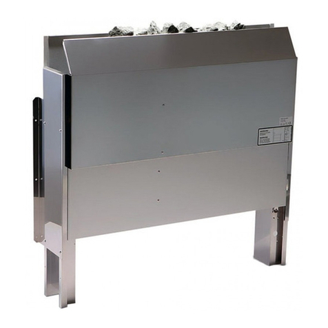
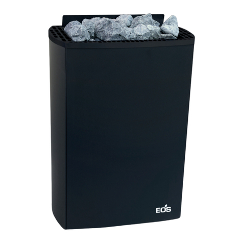
EOS Zeus User guide

1
D
MADE IN GERMANY
IPx4
Zeus
print no. 29344847 en / 34.17
EN Installation and operating instruction
sauna heater
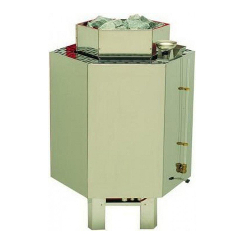
guard rail optional

2EN
English
Table of Contents
Intended use ............................................................................................................................................3
General notes...........................................................................................................................................3
Important notes......................................................................................................................................4
Scope of delivery ...................................................................................................................................7
Specifications...........................................................................................................................................7
Wiring diagrams......................................................................................................................................8
Connection examples...........................................................................................................................9
Installation and Safety gaps ............................................................................................................10
Heater guard rail installation........................................................................................................... 11
Replacement of heating elements................................................................................................ 12
Sauna stones.........................................................................................................................................13
Maintenance and care.......................................................................................................................14
Service Address....................................................................................................................................15
General Terms and Conditions of Service (ASB).......................................................................16

3
EN
Dear customer
You have purchased a high-quality technical
device with which you will have years of sauna
fun.This sauna heater was designed and inspect-
ed according to the current European safety
standards and manufactured at the factory
in accordance with the quality management
standard DIN EN ISO 9001:2008.
This detailed installation and operation manual
has been prepared for your information. Please
observe in particular the important notes and
the information on electrical connection.
We wish you exhilarating recreational experience
and lots of fun with your sauna!
Intended use
This sauna heater is exclusively intended for the
heating of sauna cabins in combination with an
appropriate control unit.
Any other use over and above the intended
purpose is not considered as appropriate use!
Compliance of the standard operation, mainte-
nance and repair conditions is also an element
of appropriate use.
The manufacturer cannot be held liable for
deviating, unauthorized alterations and any re-
sulting damages: the initiator of these changes
bears the full risk.
General information
Please check whether the unit has arrived in per-
fect condition. Any transport damages should be
immediately reported to the freight forwarder
delivering the goods or you should contact the
company that shipped the goods.
Please note that you will only be able to achieve
an optimum sauna climate if the cabin with its air
intake and ventilation, the sauna heater and the
control unit are aligned to each other.
Please observe the information and stipulations
made by your sauna supplier.
Sauna heaters heat up your sauna cabin using
heated convective air. Here, fresh air is drawn
in from the air intake which, when heated, rises
upwards (convection) and is then circulated
within the cabin. Part of the used air is pushed
out through the vent in the cabin.This creates a
typical sauna climate which can achieve temper-
atures of approx. 110°C measured directly under
the ceiling of your sauna, dropping in temper-
ature to approx. 30-40°C towards the oor. It is
therefore not unusual to measure temperatures
of 110°C on the temperature sensor hanging
over the heater, whilst the thermometer hanging
on the sauna wall, approx. 20-25 cm under the
cabin ceiling, only indicates 85°C. The bathing
temperature generally lies between 80°C and
90°C in the area of the upper bench when the
temperature is set to maximum.
Please note that the highest temperatures are
always generated over the sauna heater and that
the temperature sensor and the safety limiter
must be mounted there in accordance with the
control unit installation instructions.
When heating up for the first time, you may
notice a slight smell caused by evaporating
lubricants used in production processes. Please
ventilate your cabin before beginning your
sauna bath.

4EN
Important notes
• Unprofessional installation may
cause a re hazard! Please read these in-
stallation instructions carefully. In particu-
lar, please observe the dimensions stated
and the following notes.
• This device can be used by children aged
8 upwards and by persons with physical,
sensory, or mental disabilities, or who
have inadequate experience and knowl-
edge if they are supervised or if they have
received adequate instruction in how to
use the device safely and understand the
associated risks. Children may not play
with this device. Children may not clean
or carry out any user maintenance if un-
supervised.
• Children should be supervised to make
sure that they will not play with the unit.
• Only specialists may install and con-
nect the sauna heater, control unit and
other electrical equipment with a xed
mains connection. The necessary protec-
tive measures according to VDE 0100 of §
49 DA/6 and VDE 0100 part 703/2006-2
must be observed.
• Sauna heater and controller may only be
used in sauna cabins made of suitable,
low-resin, untreated materials (e.g. spruce).
• Only a sauna heater with the appropriate
power output may be installed in the sau-
na cabin.
• Please provide air intake and vent open-
ings in each sauna cabin. The air intakes
must always be positioned behind the
sauna heater, approx. 5 to 10 cm above
the oor. The minimum dimensions of the
air intake and vent openings are stated in
the table.
• The duct vents are always to be positioned
oset diagonally to the sauna heater in
the lower area of the rear sauna wall. The
air intake and vents may not be covered.
Please observe the sauna cabin supplier's
instructions.
• Only the control units specied here-
in must be used for the operation of the
sauna heater. This control unit must be
positioned at an appropriate point on the
cabin outer wall; the associated sensor
must be positioned inside the sauna cabin
according to the installation instructions
included with the control unit.
• Caution: Covering the heater or an
incorrectly lled stone container represent
a re hazard.
• Every time before the sauna is used,
ensure that no objects have been left lying
on the sauna heater.
• Caution: The high sauna heater
temperatures generated during operation
can cause burns.
• The sauna heater is not intended for in-

5
EN
stallation or set-up in a niche, under a
bench or under a sloping roof.
• Do not put the sauna heater into operation
when the air intake is closed.
• The cabin lighting and the corresponding
installation must correspond with the
"splash protected" version in accordance
with DIN EN VDE 0100 T 703. Therefore,
only VDE-tested sauna light with max. 40
Watt may be installed in connection with
the sauna heater.
• Only a locally certied electrician
may connect the sauna facility (sauna
heater, control unit, lighting etc.) to a xed
mains connection.
• All electrical installations and all connec-
tion lines that are installed inside the cab-
in must be suitable for an ambient tem-
perature of at least 170 °C. If single-wire
cables are used as connection lines, they
must be protected using a exible metal
tube connected to the equipment ground-
ing conductor. Please see the table for the
minimum cross-section of the connection
cable and the suitable cabin size in rela-
tion to the power input in kW.
• When installing the sauna heater, please
ensure that the vertical clearance be-
tween the sauna heater upper edge and
the sauna ceiling is maintained. Please
see also the dimensions diagram for the
clearance between the lower edge of the
sauna heater and the oor. On heaters
with bases, this clearance is maintained
via the base or legs of the device.
• Please always ensure that the sauna heat-
er is never placed on ooring made of
ammable material (wood, plastic oor-
ing etc). Ceramic tiles are recommended
as oor materials.
• Floor heating in the sauna cabin increases
the surface temperature of the ooring.
• Please see the dimensions information
for the respective sauna heater for the
clearance between the heater protective
grating or the bench and other ammable
materials. The heater protective grating
must roughly accord with the front height
of the sauna heater.
• Please also observe the information and
instructions provided by the cabin manu-
facturer.
• Please take precautions when
cleaning components with sharp edges.
• Upright heaters need to be tted on site
with elements that prevent them from
overturning.
• Attention: Pour the infusion water
only on the sauna rocks and never any-
where else.
• When using your sauna in a dry
Finnish mode never add sauna essences or

6EN
place any herbs into the vaporizer holder
for essences/herbs. Fire hazard!
• Never add more essences or vol-
atile oils than advised on the packaging.
Never use alcohol or undiluted concen-
trates.Caution! Fire hazard!
• When designing the cabin ensure
that the external exposed glass surfaces
only reach a maximum temperature of
76°C. If necessary, protective features
need to be tted.
Caution!
Dear Customer,
In compliance with the valid regulations,
only certied electricians may connect the
sauna heater and the sauna control system
to the mains power supply. Please note
that you must provide a copy of the invoice
from the electrical company who installed
the sauna in case of a warranty claim.
Electrical connection
Using the above-mentioned wiring diagram
and the information on the wiring circuit ad-
hered to the respective control system, your
electrician will be able to connect the system
without further instructions.
Please note that, for safety reasons, power ca-
bles may not be laid visibly on the interior walls
of the cabin. Most sauna cabins have empty
ducts tted into the wall element with the air
intake.
If no empty ducts are available in your cabin,
drill a suciently sized hole in the cabin wall
directly next to the place where the cable exits
the sauna heater and guide this cable outside
through the hole to the control unit. The cable,
and all other connecting cables (mains power
cables and cabin lighting), should be installed
in installation ducts or also be protected against
damage on the outside of the cabin e.g. by lay-
ing them in installation pipes or attaching wood
cover strips.
The sauna heater, if used in commercial/public
facilities and equipped with remote control*,
may be used only in combination with the ap-
propriate cover protection system or S-Guard
system.
*Remote control – means settings, switching, control
and adjustment of the sauna control unit by means of
commands transmitted from a remote location beyond
sight distance using telecommunication, wire- or wire-
less signal transmission systems, network and similar
systems.

7
EN
Specications
Scope of delivery
Power Dimensions
Ø x H in cm For cabin volume
Minimum
dimension for
air supply and
duct vent
Weight without
stones and
packaging
Stone lling
Power extension
unit (LSG)
required
To be used with the
control units
12 kW
Ø 70 x 125
14 - 18 m³ 50 x 6 cm
140 kg 130 - 140 kg
Emotec
LSG 09R
Econ series
Emotec series
EmoStyle series
EmoTouch series
16 kW 18 - 25 m³ 50 x 6 cm
20 kW 24 - 30 m³ 50 x 8 cm LSG 18
24 kW 35 - 40 m³ 50 x 8 cm
30 kW 50 - 65 m³ 50 x 10 cm LSG 36
36 kW 65 - 75 m³ 50 x 10 cm
Power Electric
connection
external
Fuse protection
control unit
Connection:
mains - control
unit
external
Fuse protection
LSG unit
Connection:
mains - LSG
Connection:
control
unit - heater
Connection:
LSG - heater
Connection:
control unit -
LSG
12 kW
400 V 3N AC
50 Hz
3 x 16 A 5 x 2,5
3 x 16 A 5 x 2,5
5 x 1,5
5 x 1,5
4 x 1,5
16 kW
5 x 620 kW 3 x 25 A 5 x 4
24 kW 3 x 35 A 5 x 6
30 kW 1 x 16 A 3 x 1,5 3 x 50 A 5 x 10 -- 2 pcs. 5 x 6
36 kW 3 x 63 A 5 x 16 2 pcs. 5 x 6
All details on cable cross-sections are minimum diameters in mm² copper line.
The standard scope of delivery includes:
• Sauna heater
• Connection cable (consists of two separate cable lines with special connectors)
• Installation and operation manual
• sauna stones (approx. 130-140 kg)

8EN
30 kW
5 x 6 2
5 x 6 2
2,5 kW
2,5 kW
2,5 kW
2,5 kW
2,5 kW
2,5 kW
2,5 kW
2,5 kW
2,5 kW
2,5 kW
2,5 kW
2,5 kW
1,66 kW
1,66 kW
1,66 kW
1,66 kW
1,66 kW
1,66 kW
1,66 kW
1,66 kW
1,66 kW
1,66 kW
1,66 kW
1,66 kW
N
N
NU
V
W
N
N
NU
V
W
N
N
NU
V
W
N
N
NU
V
W
36 kW
5 x 6 2
5 x 6 2
3,0 kW
3,0 kW
3,0 kW
3,0 kW
3,0 kW
3,0 kW
3,0 kW
3,0 kW
3,0 kW
3,0 kW
3,0 kW
3,0 kW
N
N
NU
V
W
N
N
NU
V
W
N
N
NU
V
W
N
N
NU
V
W
zum LSG 36
20 kW
5 x 1,5 2
5 x 4 2
N
N
NU
V
W
N
N
NU
V
W
N
N
NU
V
W
1,0 kW
1,0 kW
1,0 kW
1,0 kW
1,0 kW
1,0 kW
12 kW
5 x 1,5 2
5 x 1,5 2
N
N
NU
V
WN
N
NU
V
W
1,0 kW
1,0 kW
1,0 kW
1,0 kW
1,0 kW
1,0 kW
zum Steuergerät
1,33 kW
1,33 kW
1,33 kW
1,33 kW
1,33 kW
1,33 kW
1,33 kW
1,33 kW
16 kW
5 x 1,5 2
5 x 1,5 2
N
N
NU
V
W
zum LSG 09 R
N
N
NU
V
W
zum Steuergerät
zum LSG 09 R
1,33 kW
1,33 kW
1,33 kW
1,33 kW
zum LSG 18
zum Steuergerät
zum LSG 36
zum LSG 36
zum LSG 36
2,0 kW
2,0 kW
2,0 kW
2,0 kW
2,0 kW
2,0 kW
2,0 kW
2,0 kW
2,0 kW
2,0 kW
2,0 kW
2,0 kW
24 kW
5 x 1,5 2
5 x 6 2
N
N
NU
V
W
N
N
NU
V
W
N
N
NU
V
W
zum LSG 18
zum Steuergerät
Wiring diagrams

9
EN
Connection example
30 / 36 kW
400 V AC 3N
N U V W
U V W N L1 L2 L3 N
S1 V N
400 V AC 3N
fan light
L N L N
L1 L2 L3 N W V U N N
WB
WM
3 4
S1
S1 N
STB
Saunasteuergerät / Control unit /
Boîtier de commande / Пульт управления
LSG
Contactor box
Saunaofen
Sauna heater
Sensorbus
Saunabus
reserviert
N U V W
1 1 1 1
Sensor
Limiter
LSG
5 5
5
4
5
4
Saunasteuergerät
Control unit
Boîtier de commande
Пульт управления
Saunaheizgerät
Sauna heater
Poêle de sauna
Печь для сауны
Leistungsschaltgerät
Power extension unit
Extension de puissance
Блок расширения мощности
Netz / Mains / Réseau / Сеть
400 V AC 3N 400 V AC 3N
fan light
L N L N
L1 L2 L3 N W V U N N
WB
WM
3 4
S1
S1 N
STB
Saunasteuergerät / Control unit /
Boîtier de commande / Пульт управления
Sensor
Saunaheizgerät / Sauna heater
Sensorbus
Saunabus
reserviert
PE
V N S1
MAINS OVEN LSG
NL1 L2 L3 N W V U
Leistungsschaltgerät LSG 09R
U1 V1 W1 N1
PE U V W N PE
Limiter
20 / 24 kW
12+16 kW

10 EN
Installation
The sauna heating unit is designed for operation with an input voltage of 400V AC 3N through the
sauna control unit and a separate power extension unit.
Sauna heaters maybe operated via remote control* only in combination with an approved safety
system like EOS switch-o guard rail.
*Remote control – means settings, switching, control and adjustment of the sauna control unit by means
of commands transmitted from a remote location beyond sight distance using telecommunication,
wire- or wireless signal transmission systems, network and similar systems
Minimum clearances
The sauna cabin must have a minimum inside height of 210 cm.
The vertical gap between the top of the sauna heater and the inner surface of the sauna ceiling must
be at least 130 cm, the horizontal gap between the heater and the cabin wall or other ammable
materials must be at least 10 cm.
The distance between the heater guard and/or bench and other ammable materials must be at
least 10 cm.The height of the heater guard must be the same as the height of the front of the stove.
mind. 1300
Sensor
320
~1250
Maße in mm
mind.
100
mind.
100

11
EN
Heater guard rail installation (optional)
The round-shaped guard rail is optionally available.
Please bear in mind that you will also need the set of
mounting brackets as well.
1. Lift the ring-shaped top cover
2. Disconnect the connectors for both power supply
lines (open clip and pull o).
3. Unmount (unscrew) two securing handles (3) on the
outer side of the housing.
4. Remove the heating block by pulling it up out of the
heater.
5. Unscrew 3 headless screws (plugs) located in the
upper part around the heater housing. The 3 holes
serve for mounting the guard rail support brackets.
6. Mount the 3 separately supplied guard rail holders
(metal pins) to the guard rail. Each holder has a small
metal plate with 4 holes. Insert this plate into the
corresponding groove milled in the rail and secure
it with 4 screws.
1.
4.
3x
2x
2.
3.
5.
6.
7.
1x
7. Now take the guard rail and set it down on the
heater until the metal holders are lined up with
the corresponding holes in the housing. Atten-
tion - be careful not to scratch the housing!
8. Secure the rail holders (pins) from inside the heat-
er through the wall with the supplied M8 screws
with hexagonal head.
9. Place the heating block back in the original po-
sition and restore the power supply connection.
Make sure to secure the connectors with safety
clips.
10.Place the top cover ring back in the original po-
sition.
1.
4.
3x
2x
2.
3.
5.
6.
7.
1x
1.
4.
3x
2x
2.
3.
5.
6.
7.
1x

12 EN
2.
3.
4.
1.
Replacement of heating elements
Access to cable
connectors
View from top
7. The heating elements are tted in the
base plate and secured underneath it with
nuts with fan-shaped washers.
8. Pull o the inner wiring from the heating
element terminals and loosen the moun-
ting nut. Take the heating element out.
Install the new element in the reverse or-
der and connect it.
9. Mount the cover panel of the terminal
box back in position and secure it with 2
screws.
10. Set the heating element block back into
the housing and secure it with 4 screws.
11. Set the decoration ring back on top and
ll the stones into the rock store.
12. Connect the power supply cables.
1. Remove stones from the rock store.
2. Loosen 4 securing screws (1) in the base
plate of the heating block.
3. Lift up and take o the decoration ring
(2).
4. Disconnect the plugs of the power sup-
ply cables on the bottom of the heater
through the side opening.
5. Lift up the heating block (3) and take it
out of the heater
6. Loosen two screw of the terminal box co-
ver (bottom side) and take this panel o.
Notice:
Use sauna stones with the size 100/150 mm.
Make sure to observe the advice for sauna
rocks on the next page.

13
EN
Please be sure to note!
Do not insert sauna rocks too tightly in
the rock store. Place them loose, leaving
as many spaces as possible to allow the
free ow of hot air for circulation purpos-
es.
Remove stones from the sauna heater
only when they cooled down.
It cannot be excluded that hot rocks or
their parts fall out of the rock store.
Risk of re!
Sauna stones are a natural product. Check the
sauna stones at regular intervals. Aggressive
sauna essences can weaken the sauna stones
and cause them to break apart over time. Con-
sult your sauna supplier if necessary.
Rinse the sauna stones provided under running
water and then place them in the stone com-
partment so that the convection air ow can
circulate easily between the stones.
The quantity of stones is sucient to create a
steam shock, vaporizing about 10 cl of water
per m³ cabin volume. Always wait at least 10
minutes after an infusion before repeating it.
Only then the sauna stones will re-heat su-
ciently again.
Never add more essences or vola-
tile oils than advised on the packaging.
Never use alcohol or undiluted concen-
trates. Caution! Fire hazard!
All sauna heating units are made of low-corro-
sion material. To enjoy your sauna heating unit
for a long time you should ensure maintenance
and take due care about the heater. Always
make sure that the air supply vents and reec-
tion surfaces in the area of air intake are free.
These can easily become clogged with fuzz and
dust when drawing in fresh air. This reduces the
air convection in the sauna heating unit and
can be a cause of too high temperatures.
Clean or de-scale the heater when needed.
Refer to your sauna supplier or directly to the
manufacturer in case of defects or signs of wear
and tear.
Only use original manufacturer‘s replacement
parts, which can be obtained from your suppli-
er or directly from the manufacturer.
If you did not use your sauna for a long peri-
od of time, always check before next use that
cloths, cleansers or other objects have not
been left on the sauna heating unit or the va-
porizer before turning them on.
Sauna rocks Maintenance and care

14 EN
For the installation of sauna heaters, please
pay attention to the DIN VDE 0100 part 703 or
the corresponding national norms and legal
requirements, e.g. UL875 norm!
This standard makes the following statement
valid in your newest expenditure, since Febru-
ary 2006, paragraph 703.412.05; Quotation:
The addition must be planned for all electric cir-
cuits of the Sauna by one or more fault current
protection device (RCDs) with a calculation dier-
ence stream not more largely than 30 mA, exclud-
ed of it is Sauna heating.
The EN 60335-1 DIN (VDE 0700 part 1):2012-10
states the following in paragraph 13.2; quote:
The leakage current may not exceed the following
values during operation:
- for stationary heaters of protection class I 0,75
mA; or 0,75 mA each kW input of the appliance,
depending on the higher value, at a maximum
value of 5 mA.
If the appliance is equipped with a protective
device for leakage current (ELCB), please pay at-
tention to the fact that no other electrical units
will be protected by this ELCB.
Under current manufacturing technology, it is
not reasonable to use heating elements for sau-
na heaters which do not collect moisture from
the surrounding air. It is therefore possible that
a little bit of moisture from the surrounding air
may reach the magnesium-oxide lling in the
heating elements during transport or storage
and may cause the ELCB to release.
In this case the heater must be heated up un-
der supervision of an expert, during which
the Ground conductor is not connected. After
about 10 minutes, when moisture has evapo-
rated from the heating elements, the heater
must be reconnected to the Ground conductor!
If the sauna heater is not in use for a signicant
period of time, we recommend running it every
6 weeks, so as to avoid moisture concentrating
in the heating elements.
Therefore, should the ELCB be released dur-
ing start-up, the electrical installation must be
checked.
Installation of the sauna heater and control unit
must be undertaken only by an authorized and
appropriated qualied electrician.
Without a documented proof of such installa-
tion a warranty is generally void.

Service Address:
EOS Saunatechnik GmbH
Schneiderstriesch 1
35759 Driedorf, Germany
Tel: +49 (0)2775 82-514
Fax: +49 (0)2775 82-431
www.eos-sauna.de
Please keep this address in a safe place togeth-
er with the installation guide.
To help us answer your questions quickly and
competently please provide the information
printed on the type shield including the model,
item no. and serial no., in all inquiries.
Equipment commissioning date:
Stamp and signature of the authorized elec-
trician:
15
EN

General Terms and Conditions of Service
I. Scope
Unless otherwise agreed in writing in a specic case,
these terms and conditions of service shall apply to ser-
vice operations, including examining and repairing com-
plaints. All our existing or future legal relationships shall
be governed solely by the following terms and condi-
tions of service. Our recognition of any conicting terms
and conditions of the Ordering Party shall be conditional
upon our having given our express written consent to
their applicability. We hereby expressly object to any
terms and conditions of the Ordering Party contained
in its General Terms and Conditions of Business or order
conrmation. If order conrmations or deliveries are ac-
cepted without reservation, this shall not be deemed to
constitute recognition of such terms and conditions. Any
ancillary agreements or amendments must be conrmed
in writing.
II. Prices and Payment Terms
The Ordering Party shall bear the following costs in
connection with the service operation:
• Disassembly/assembly and electrical (de-) instal-
lation
• Transportation, postage and packaging
• Function testing and troubleshooting including
inspection and repair costs
There shall be no third-party billing.
III. Performance Obligations / Ordering Party‘s
Cooperation
The Ordering Party shall provide free-of-charge assis-
tance to the manufacturer in carrying out the service
operation.
In the case of a warranty claim, the manufacturer
shall make the replacement parts necessary for the
service available to the Ordering Party free of charge.
IV. Service Visit by the manufacturer
In the event that it is essential that a manufacturer
employee carry out the service operation on site, this
must be agreed in advance. Where the main reason
for the service call is not the fault of the manufactur-
er, any costs incurred shall be recharged to the Order-
ing Party after the service visit.
V. Liability
The manufacturer shall assume liability in accordance
with the currently applicable statutory regulations. The
packaging for all of our products is designed for the ship-
ping of individually packed goods (pallet). We expressly
point out that our packaging is not suitable for individual
shipments via parcel post.The manufacturer shall accept
no liability for damage incurred as a result of improper
packaging in an individual shipment.
VI. Manufacturer‘s Warranty
The manufacturer‘s warranty shall apply only in the
event that installation, operation and maintenance have
been carried out in accordance with the manufacturer‘s
specications contained in the assembly instructions
and instructions for use.
• The warranty period shall commence from the date
on which proof of purchase is provided and shall be
limited, in principle, to 24 months.
• Warranty services shall be performed only if the
proof of purchase relating to the equipment can be
presented.
• Any and all warranty claims shall become void if
modications are made to the equipment without
the manufacturer‘s express consent.
• Any warranty claim shall likewise become void in
the case of defects that arise due to repairs or inter-
ventions made by unauthorized persons or due to
improper use.
• In the case of warranty claims, the serial and article
numbers must be indicated together with the desig-
nation and a meaningful description of the fault.
• This warranty shall cover defective equipment parts,
with the exception of normal wear parts. Wear parts
shall include, among other things, light sources, start-
ers, gas or oil pressure dampers as well as acrylic glass
panes, tubular heating elements and sauna heater
stones.
• Only original replacement parts may be used within
the warranty.
• Service visits by outside companies shall require a
written order to be issued by our service department.
• The equipment in question shall be sent to our
service department by the Ordering Party and at its
expense.
• Electrical assembly and installation work, including
in the event of service or replacement, shall be car-
ried out at the Customer‘s expense and shall not be
borne by the manufacturer.
Complaints in respect of our products shall be reported
to the specialist trader responsible and shall be exclu-
sively handled via the latter.
The manufacturers General Terms and Conditions of
Business, as amended, shall apply in addition to the fore-
going terms and conditions of service.
As of 06/2015
16 EN
Other manuals for Zeus
1
Table of contents
Other EOS Heater manuals
Popular Heater manuals by other brands

TriStar
TriStar KA-5060 instruction manual

Johnson & Starley
Johnson & Starley WARMCAIR C16D manual

Dimplex
Dimplex CVP1 Installation and operating instructions

VOGEL&NOOT
VOGEL&NOOT NERO Assembly and operating manual

Silvercrest
Silvercrest SKD 2300 A1 operating instructions

Greenheck
Greenheck DGX Installation, operation and maintenance manual