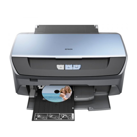
EPSON Stylus PHOTO 870/1270 Revision B
7
Troubleshooting with LED Error Indicators .................................57
Error Conditions .............................................................................58
Remedies for Paper Out Error ......................................................60
Remedies for the Paper Jam Error ...............................................62
Remedies for No Ink Cartridge Error/Ink Cartridge Problem .....63
Remedies for Maintenance Request Error ...................................63
Remedies for Fatal Error ...............................................................64
Isolating the Faulty Part on the Power Supply Board ........................67
Isolating the Faulty Part according to the Phenomenon ....................69
DISASSEMBLY AND ASSEMBLY
OVERVIEW ..................................................................................................74
Precaution for Disassembling the Printer ............................................74
Tools .......................................................................................................75
Specifications for Screws .....................................................................76
Service Checks After Repair .................................................................77
DISASSEMBLY PROCEDURES ..................................................................78
HOUSING Removal ...............................................................................79
Circuit Board Assembly Removal ........................................................80
Panel Unit Removal ...............................................................................83
Printhead Unit Removal ........................................................................85
TRAY, ABSORBER ASSEMBLY Removal ............................................87
Ink Unit Removal ...................................................................................89
MOTOR ASSEMBLY, CR Removal .......................................................92
MOTOR ASSEMBLY, ASF Removal .....................................................93
DE Unit Removal ...................................................................................94
ASF Unit Removal .................................................................................97
SHAFT, ROLLER, LD Removal ......................................................99
ROLLER ASSEMBLY, LD, RIGHT/LEFT Removal .......................104
Carriage Unit Removal ........................................................................105
BOARD ASSEMBLY, ENCODER Removal .........................................107
ROLLER, PF Removal ..........................................................................108
SCALE, PF Installation .................................................................111
MOTOR ASSEMBLY, PF Removal ......................................................114
PE Sensor Unit Removal .....................................................................115
ADJUSTMENT
OVERVIEW ................................................................................................117
Adjustment Items ................................................................................117
Adjustment Tools ................................................................................118
ADJUSTMENT ..........................................................................................119
Parallelism Adjsutment ......................................................................119
Backlash Adjsutment ..........................................................................121
Using the Adjustment Program .........................................................123
About the Adjustment Program .................................................123
How to Install the Program .........................................................123
How to Uninstall the Program ....................................................123
Starting the Service Program .....................................................124
Market destination check ...................................................................125
Head voltage ID input .........................................................................126
Where to Find the Head ID ..........................................................126
Check Present Data ......................................................................126
Change Data .................................................................................127
Head angular adjsutment ...................................................................128
Bi-Directional adjustment ..................................................................130
USB ID check/input .............................................................................132
Inputting/Checking the USB ID ...................................................132
Head cleaning ......................................................................................134
Initial ink charge ..................................................................................135
Protection counter check ...................................................................135
Check the Present Counter Value ...............................................135
Clear the Protection Counter Values ..........................................136
CSIC information .................................................................................137
Print A4 pattern ...................................................................................137
MAINTENANCE
OVERVIEW ................................................................................................139
Cleaning ...............................................................................................139
Service Maintenance ...........................................................................139
Head Cleaning ..............................................................................139
Maintenance Request Error Clear ..............................................139
Lubrication ...........................................................................................140
APPENDIX
CONNECTOR SUMMARY ........................................................................147
Connector Pin Assignment .................................................................147
