manuals.online logo
Brands
  1. Home
  2. •
  3. Brands
  4. •
  5. Erreka
  6. •
  7. Gate Opener
  8. •
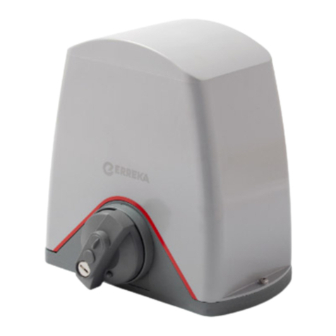
  9. Erreka PUMA-I Operating instructions

Erreka PUMA-I Operating instructions

Other manuals for PUMA-I

1

Other Erreka Gate Opener manuals

Erreka ARC Series User guide

Erreka

Erreka ARC Series User guide

Erreka Puma User guide

Erreka

Erreka Puma User guide

Erreka VIVO-M101 Operating instructions

Erreka

Erreka VIVO-M101 Operating instructions

Erreka VULCAN D Operating instructions

Erreka

Erreka VULCAN D Operating instructions

Erreka CALYPSO Series User manual

Erreka

Erreka CALYPSO Series User manual

Erreka KAIROS MSB-027/01 User manual

Erreka

Erreka KAIROS MSB-027/01 User manual

Erreka TORO KM1800 Operating instructions

Erreka

Erreka TORO KM1800 Operating instructions

Erreka VULCAN D VUA12 User guide

Erreka

Erreka VULCAN D VUA12 User guide

Erreka MAGIC User guide

Erreka

Erreka MAGIC User guide

Erreka JEDI JES100E User manual

Erreka

Erreka JEDI JES100E User manual

Erreka BUL BL33 Operating instructions

Erreka

Erreka BUL BL33 Operating instructions

Erreka SIRIUS Operating instructions

Erreka

Erreka SIRIUS Operating instructions

Erreka VIVO-M201M Operating instructions

Erreka

Erreka VIVO-M201M Operating instructions

Erreka VULCAN User guide

Erreka

Erreka VULCAN User guide

Erreka MAGIC Operating instructions

Erreka

Erreka MAGIC Operating instructions

Erreka MAGIC User guide

Erreka

Erreka MAGIC User guide

Erreka AXIL Operating instructions

Erreka

Erreka AXIL Operating instructions

Erreka Fenix User guide

Erreka

Erreka Fenix User guide

Erreka CICLON Operating instructions

Erreka

Erreka CICLON Operating instructions

Erreka V2 CICLON User manual

Erreka

Erreka V2 CICLON User manual

Erreka MAGIC User guide

Erreka

Erreka MAGIC User guide

Erreka TORO KM1800 Operating instructions

Erreka

Erreka TORO KM1800 Operating instructions

Erreka DINGO Operating instructions

Erreka

Erreka DINGO Operating instructions

Erreka AXIL Series User manual

Erreka

Erreka AXIL Series User manual
Popular Gate Opener manuals by other brands

Nortek Security & Control Mighty Mule HD272 installation manual

Nortek Security & Control

Nortek Security & Control Mighty Mule HD272 installation manual

tousek TURN 10 Installation and operating instructions

tousek

tousek TURN 10 Installation and operating instructions

SOMFY AXOVIA 220B RTS installation instructions

SOMFY

SOMFY AXOVIA 220B RTS installation instructions

Nice HySecurity CBOX1050 Installation and programming manual

Nice HySecurity

Nice HySecurity CBOX1050 Installation and programming manual

CAME FROG-PM4 installation manual

CAME

CAME FROG-PM4 installation manual

Aprimatic ONDA 500 installation instructions

Aprimatic

Aprimatic ONDA 500 installation instructions

Turnstiles FSW 900 manual

Turnstiles

Turnstiles FSW 900 manual

Extel VERA quick guide

Extel

Extel VERA quick guide

Beninca R1-2 WBV quick start guide

Beninca

Beninca R1-2 WBV quick start guide

Motorline professional FORT User& installer's manual

Motorline professional

Motorline professional FORT User& installer's manual

Beninca BOB5024 manual

Beninca

Beninca BOB5024 manual

AGA GATEMASTER 900 HD installation manual

AGA

AGA GATEMASTER 900 HD installation manual

Cardin BL Series manual

Cardin

Cardin BL Series manual

Westfalia 85 27 06 instruction manual

Westfalia

Westfalia 85 27 06 instruction manual

Riello Elettronica CARDIN ACE FAST Instruction handbook

Riello Elettronica

Riello Elettronica CARDIN ACE FAST Instruction handbook

Telcoma ARM Instruction handbook

Telcoma

Telcoma ARM Instruction handbook
Telcoma ACE Instruction handbook

Telcoma

Telcoma ACE Instruction handbook

DCS MEGA ARM Installation and service manual

DCS

DCS MEGA ARM Installation and service manual

manuals.online logo
manuals.online logoBrands
  • About & Mission
  • Contact us
  • Privacy Policy
  • Terms and Conditions

Copyright 2025 Manuals.Online. All Rights Reserved.

9
PUMA-I
Quick installation and programming guide English
WARNING
This quick guide is a summary of the complete installation manual. The manual contains safety warnings and
other explanations which must be taken into account. The installation manual can be downloaded by going
to the "Downloads" section of Erreka website:
http://www.erreka-automation.com
D268A
2
D268B
2
3
E268C
Assembly levels (mm) Unlocking
Locking for operation
motorised:
•Turn the handle (2) anti-clockwise 270°
without forcing it.
•Turn the key (1) anti-clockwise and remove.
•Push the cylinder (3) inward and manually
move the gate to interlock it in the operator
mechanism
E268D
Electrical wiring
A: Main power supply
B/E: Flashing light/Antenna
C: Photocells (Tx / Rx)
D: Pushbutton/wall key
Elements of the complete installation
Unlocking Locking
Unlocking for manual
operation:
•Insert the key (1) and
turn clockwise without
forcing it.
•Turn the handle (2)
clockwise 270°,
through to the stopper
but without forcing it.
WARNING: The PUMA-I
operator is supplied
without a capacitor for the
motor, since the control
board's Inverter
technology makes it
unnecessary. If this board
is used to replace another
operator, do not use a
capacitor for the motor.
1
10
R.E.
(ST1)
(ST2)
(DIP6=OFF: FCA)
(DIP6=ON: FCC)
FC1
(DIP6=OFF: FCC
(DIP6=ON: FCA)
FC2
P268Y
DL1 DL2 DL3
ST1
ST2
SW1
DL6
F1-0,315A
SW2
F5-3A F6-0,5A
ST1
FT1
ST2
FT2
+12 GND
STOP LAMP
G2 G1 C N L
MOTOR POWER
(FT1)
SG. A (FT2)
RADIO
RECEIVER
DL21
DL8
Waiting
Time
POT2
DL11 DL
DL9
DL10
(12Vdc)
G2
G1
C
DL26
General connections
DIP6=OFF DIP6=ON
Check and configure turning direction and limit switches
Encoder (DIP7): for the correct operation of the encoder, ensure DIP7 is in ON. The operation needs to be
reprogrammed if the encoder is disabled.
Check that DL21 flashes during gate movement.
‹A capacitor should not be used for the motor with the PUMA-I
operator fitted with Inverter technology control board.
DL1 Automatic closing LED
DL2 Radio programming LED
DL3 Travel programming LED
DL6 FT2 photocell LED
DL7 FC1 limit switch LED
DL8 FC2 limit switch LED
DL9 FT1 photocell LED
DL10 ST2 pushbutton LED
DL11 ST1 pushbutton LED
DL21 Encoder LED
DL26 DC Bus LED
‹
Motor with
no capacitor
Turning direction: check operation using ST1 and ST2 mini-pushbuttons with DIP1=ON. If turning direction is not as
indicated for position DIP6, interchange the wires connected to the G1 and G2 terminals.
PEDESTRIAN
TOTAL
E268L
SW1
SW1 Functions during programming (DIP1=ON)
DIP1=ON: programming enabled (DL3 lights up); ST1: open, ST2: close
DIP1=ON and DIP2=ON: total open/close programming
DIP1=ON and DIP3=ON: pedestrian open/close programming
DIP1=ON and DIP4=ON: total opening radio code programming
DIP1=ON and DIP6=ON: pedestrian opening radio code programming
11
Total opening radio code programming (with RSD receiver only)
1 Connect the power supply and
close the gate with DIP1 in ON
position and keeping ST2 pressed
down.
2 Select the code in the transmitter. 3 Place the DIPs as shown in the
figure (DIP1=ON, DIP4=ON). DL3
lights up to show programming
mode enabled.
R268A
ST2
R268C
R268B
SW1
4
Press the button of the required channel
.
DL2 flashes when programming is complete
.
5 Place DIP1 and DIP4 in OFF.
DL3 remains off.
6 Disconnect and reconnect the
electrical power supply.
Programming is carried out in the
same way, using DIP6 instead of DIP4.
R268D
R268E
SW1
Pedestrian opening radio
code
ZIf a receiver other than RSD is used, see the corresponding instructions.
Total open/close programming
1
Connect the power supply and close
the gate with DIP1 in ON position
and keeping ST2 pressed down.
2 Place the DIPs as shown in the
figure (DIP2=ON, DIP1=ON).
DL3 lights up to show
programming mode enabled.
R268A
ST2
G268Z
SW1
3 Press ST1 to start opening. 4 Press ST1 to start slowdown. 5 Wait for it to come to a stop at the
end of travel.
G268A
ST1
G268B
ST1
6 Press ST1 to start closing. 7 Press ST1 to start slowdown. 8 Wait for it to come to a stop at the
end of travel.
G268D
ST1
G268E
ST1
9 Place DIP1 and DIP2 in OFF. DL3
remains off.
R268E
SW1
Pedestrian open/close programming
This is carried out in the same way as total travel
programming, with the following differences:
•DIP1 and DIP3 are used instead of DIP1 and DIP2
•ST2 is used instead of ST1
•In step 5, stop the gate with ST2
12
DIP Modes and functions Option Effect
DIP1 OFF
DIP2 Advance warning
ON the flashing light comes on and the operation begins after a 3
second warning
OFF the flashing light comes on and the operation begins
immediately
DIP3 Opening mode
ON step-by-step opening (the gate halts if a key command is
activated during opening, and closes if activated again)
OFF collective opening (the control board does not obey the key
commands during opening)
DIP4 Automatic or step-by-step mode
(for pedestrian and total operation)
ON automatic mode (the gate closes automatically after standby
time has passed, which is adjusted using T.E.). A key command
(or photocell activation) causes standby time to restart
OFF step-by-step mode (the gate only closes when receiving the key
command)
DIP5 Automatic mode optional
(only if DIP4 = ON)
ON during standby, the gate obeys the key commands (can be
closed before standby time finishes)
OFF the gate cannot be closed until standby time finishes; a key
command will cause standby time to restart
DIP6 Gate movement
direction
ON gate which opens to the left
OFF gate which opens to the right
DIP7 Encoder ON encoder enabled
OFF encoder disabled
DIP8 Slowdown ON the gate reduces its speed before reaching the stopper
OFF the gate reaches the stopper at high speed
Function and mode selection using SW1 (DIP1 = OFF)
T.E (Standby Time): gate open standby time
If automatic functioning mode has been programmed
(DIP4=ON), set T.E. to adjust standby time with the gate
open (before automatic closing begins).
•Minimum value: 0 seconds; maximum value: 90
seconds
P.M (Torque Regulator): motor torque
Use P.M. to adjust the maximum motor power value.
‹Adjust the torque to respect the maximum closing
thrusts set out in Standard EN12453:2000. Make
the measurements as described in Standard EN
12445:2000.
Waiting
Time
POT2
P268M
Potentiometer adjustment