Esco YAK 221/N User manual

Equipment Supply Company
Instruction Manual
YAK 44/22 Ton Jack
ESCO #92004
Copyright © 2020 Equipment Supply Co., All rights reserved
REV.7.20.A

FOREWORD........................................................................................................................................................... 3
SAFETY REGULATIONS ....................................................................................................................................... 3
PACKING ................................................................................................................................................................ 4
PUTTING INTO OPERATION ................................................................................................................................ 4
USE ........................................................................................................................................................................ 5
WARRANTY ........................................................................................................................................................... 5
MAINTENANCE JOBS FOR THE END USER ...................................................................................................... 6
MAINTENANCE RESERVED TO A PROFESSIONALLY QUALIFIED ENGINEER .............................................. 6
TECHNICAL DATA SHEET..................................................................................................................................... 9
DRAWINGS ........................................................................................................................................................... 10
REQUESTING SPARE PARTS .............................................................................................................................. 12
2

FOREWORD
Dear Customer, before using the jack, carefully read these instructions and become acquainted with the safety symbols.
- This handbook is an integral part of the machine which must be kept safely and be handy for the worker to consult
whenever needed.
- The contents of this manual comply with Machine Directive 2006/42/CE and the jack is type approved in conformity with
the European Norm EN 1494 and following amendments.
- The manufacturing company reserves the right to make modifications without prior notice and without incurring any
sanctions whatsoever, without prejudice to the safety and main technical characteristics.
- Failure to observe the instructions may cause personal injury, which in some cases may be mortal.
- The manufacturer is not liable for any damage to things or injury to people caused by an erroneous or incorrect use of its
product. The identification plate is on the side of the casing. DWG. 1
SAFETY REGULATIONS
- Only authorised personnel are allowed to use the equipment and they must know the contents of this operating and
maintenance handbook.
-The jack is an apparatus for lifting only and not for supporting, it is therefore absoltely forbidden to work in any
way under the vehicle being lifted until it is placed on the relative stands. DWG. 2
- Before starting to lift a vehicle it has to be blocked with the parking brake and/or by putting wedges under the wheels, as
illustrated in figure DWG. 3
- If the vehicle is loaded check load stability when lifting.
- Place the jack so that the load is centred over it and where the gripping points are indicated by the vehicle manufacturer.
DWG. 4
- During lifting and lowering, it is necessary to check there are no persons or animals under the suspended load or in the
vicinity.
- Before lowering the load make certain the handle is in the horizontal position. DWG. 5
- Never lift loads on sloping, uneven or soft ground. DWG. 6
- If extensions are needed use only those supplied by the manufacturer with the jack.
Do not use extensions without the relevant plate. Never use more than two extensions. DWG. 7
- Do not lift the load in a confined space so as not to run the risk of getting trapped.
- It is forbidden to use more than one jack simultaneously on the same load.
- Never tamper with the pressure relief valve that has the guarantee seal. DWG. 8
- Do not leave any pressure in the pistons at end of stroke when there is no load
3

PACKING
- The body, handle and other parts of the jack are packed in a three-layer corrugated cardboard box with pallet; the
operating and maintenance manual plus the warranty certificate in a folder are also inside the box.
- The instruction “Keep upright” is clearly visible on the cardboard box containing the jack.
- Depending on the number of jacks shipped, pallets of different sizes are used.
- Either transpallets or forklift-trucks are used for handling.
PUTTING INTO OPERATION
ASSEMBLY
1. Take the handle, the jack and the extensions out of the cardboard box.
2. Loosen the two nuts POS. 14 EXPLODED DRAWING YAK221/NPOS. 14 EXPLODED DRAWING YAK221/N from inside the chassis. DWG. 10
3. Loosen screw POS. 13 YAK221/NPOS. 13 YAK221/N from the chassis and remove parts POS. 9, 10, 11, 12 YAK221/NPOS. 9, 10, 11, 12 YAK221/N keeping them
assembled.
4. Fit the handle (the air distributor must be facing the pistons) inserting the coupling in the groove , put the parts removed
previously into the hole of the handle, tighten screw POS. 13 YAK221/NPOS. 13 YAK221/N and then tighten nut POS. 14 YAK221/NPOS. 14 YAK221/N .
5. Connect the two air pipes between the jack and the handle with the quick couplings on the chassis respecting the colour
indication as showed on the sticker on the chassis itself. DWG. 11
CONNECTION TO THE COMPRESSED AIR SYSTEM
- Compressed air enters into the jack circuit through the quick coupling on the top of the manual lifting/descending controls;
it is therefore necessary to have a connecting pipe with a quick coupling compatible with that of the jack. Check that the air
supply pipe has a useful passage of at least 6 mm and it is not pinched or restricted anywhere. DWG. 12
WORKING AIR PRESSURE: 116 - 145 PSI
- Absolutely never put the following into the compressed air circuit: hydraulic or Vaseline oil, brake liquid, kerosene or other
liquids.
-Install a filter dehumidifier-lubricator unit in the compressed air system.
- If you want to lubricate the compressed air circuit use exclusively:
4

ACCESSORIES
The jack is supplied with two extensions or height adapters (120 mm the long extension, 70 mm the short extension), a
circular tooth plate (10 mm plate) and an extension holder.
Never use more than two extensions! The manufacturer is not liable for any damage resulting as a
consequence of disregard for the above indications and the warranty conditions are invalidated thereof!
SCRAPPING AND DISPOSAL
- The lubricants must be disposed of in compliance with the anti-pollution laws in force.
- Scrapping the jack and its component parts must be carried out by the user in accordance with current laws.
USE
IMPORTANT: It is mandatory that the jack be used or activated in the horizontal position so as not to
compromise its operation.
- Expressly observe the safety rules already described in this manual.
1) Position the jack under the supports as described in the manual of the vehicle the manufacturing company is not
responsible for any break or damage to the lifted vehicle or to persons or property due to an incorrect use of the
jack.
2. The handle positioning lever (A) is on the left in relation to the worker; by moving it upwards the stopping system is
released so the worker can then choose one of the three possible handle positions. DWG. 13
3. When control (B) is in the perfectly central position, the jack is in the idle status.
4. By turning control B, located near the handle, towards the right in relation to the worker, the jack lifts the load.
5. By turning control B, located near the handle, towards the left in relation to the worker, the jack lowers the load. DWG.
13
6. After lifting the load, it is absolutely essential to rest it on the support stands before doing any work under it.
Remember that the jack is a lifting device and not a supporting device!
- The operator’s employer will have to provide the necessary training and furnish the necessary information about
the pumping and shifting forces.
- If the distributor breaks during use, work directly on the flow of air, closing the safety cock no. between the quick coupling
of the air inlet and the distributor itself. DWG. 14
-Before working with the jack, it is advisable to perform a few operations with no load in order to acquire the
sensitivity necessary to work safely with the jack.
- When the jack is not used, always keep the pistons lowered
IMPROPER USE
The air-hydraulic jack has been designed and made to lift transport vehicles. Any other use of the jack, such as for
instance lifting and/or moving persons, is considered to be definitely improper. All use of the jack not in conformity with the
safety rules listed in this manual is considered to be improper use.
WARRANTY
This jack is covered by a 12-month warranty starting from the date the jack leaves our factory if it has not been extended
on-line; it covers all manufacturing defects but not transport expenses, defects caused by improper use or damages
suffered during transport. For more details please see the card attached to this manual.
5

MAINTENANCE JOBS FOR THE END USER
- To ensure your jack a long life it is advisable to clean the pistons externally once a fortnight.
- Check the level of oil in the tank at least twice a year.
CHECK THE OIL LEVEL
IMPORTANT: the maximum quantity of oil in this jack is 1.2 L. Compatible oil: ATF DEXRON IID
Please follow the steps listed here to check the oil level:
1. Bleed off the air (see procedure in the next section)
2. Position the jack horizontally with the pistons down
3. Undo the screw, POS. 24 GRP1GCIPOS. 24 GRP1GCI (see DWG 15)
4. If, once this screw has been undone, no oil comes out it means the level is too low. Add oil in this case. The level must
be at the height of the small bolt on the side of the tank, under the casing.
5. If oil does come out, let the excess quantity drain off until the right level is reached (see point 4).
AIR BLEEDING
Each time the jack is serviced, removing and refitting parts connected to the tank and motorpump, it is advisable to bleed
off all air. Bleeding phases:
1. The pistons must be moved out completely.
2. Remove the casing and close the cock no. POS. 9 GRP1SOLPOS. 9 GRP1SOL.
3. Turn the jack over on to one side, leaving free access to the dowel no. POS. 17 GRP1GCIPOS. 17 GRP1GCI on the side of the base.
DWG. 16
4. Loosen (NEVER unscrew the dowel completely!) the dowel no. POS. 17 GRP1GCIPOS. 17 GRP1GCI and move the pistons back in by
hand.
5. Let all the air out from the dowel and continue until oil starts coming through and then close the dowel.
6. Put the jack back into the working position.
7. Open the cock POS. 9 GRP1SOLPOS. 9 GRP1SOL.
8. Move the pistons back in completely and check oil level.
9. Try to operate the jack without any load and if the piston lowers in jerks repeat the procedure at least 2 or 3 times.
MAINTENANCE RESERVED TO A PROFESSIONALLY QUALIFIED
ENGINEER
Having to carry out maintenance or overhauling, use exclusively genuine spare parts to ensure the utmost reliability for the
jack.
PROBLEMS
Solutions
THE MOTOR WILL NOT START, OR IT RUNS BADLY.
- Check that the air supply line is not choked.
- The outside seals fitted on the piston, POS. 10 GRP1GMP EXPLODED DRAWINGPOS. 10 GRP1GMP EXPLODED DRAWING are worn. Replace them (kit
KMYAK221/N) and lubricate both the cylinder and the ram.
6

THE JACK DOES NOT LIFT THE LOAD.
-Check that the tap POS. 9 GRP1SOLPOS. 9 GRP1SOL is open.
- Check the oil level by means of the screw POS. 24 GRP1GCIPOS. 24 GRP1GCI on the tank.
- There is dirt underneath the valves: remove the casing, close the tap POS.9 GRP1SOLPOS.9 GRP1SOL, turn the jack over so the
cylinder is horizontal and the motor pump vertical, loosen the cap POS.16 GRP1GMPPOS.16 GRP1GMP, remove the bearings and
springs and blow inside to thoroughly clean it. Reassemble and if necessary knock again the bearings POS.12 ANDPOS.12 AND
POS.14 GRP1GMPPOS.14 GRP1GMP, then repeat the bleeding operation illustrated on the previous page. Put the jack back into its
normal position and reopen the tap.
- Check the hydraulic block POS.2 GRP1SOLPOS.2 GRP1SOL, paying special attention that the piston pos.4 of the GRP1GBL
exploded drawing which controls opening and closing of the descent valve pos.7 of the GRP1GBL exploded drawing,
has not become rigid, in which case dismantle and grease it.
THE JACK LIFTS, BUT COMES DOWN UNDER THE LOAD.
- Dismantle the assembly POS.2 GRP1SOLPOS.2 GRP1SOL and check that under the bearing POS.7 GRP1GBLPOS.7 GRP1GBL there are no impurities.
After carefully cleaning, readapt the pin POS.7 GRP1GBLPOS.7 GRP1GBL in its seat with a light blow with a hammer. If the load still
falls even after fitting the jack, carry out the following step. - There is dirt underneath the valves: remove the casing,
close the tap POS.9 GRP1SOLPOS.9 GRP1SOL, turn the jack over so the cylinder is horizontal and the motor pump vertical, loosen the
cap POS.16 GRP1GMPPOS.16 GRP1GMP, remove the bearings and springs and blow inside to thoroughly clean it. Reassemble and if
necessary knock again the bearings POS.12 AND POS.14 GRP1GMPPOS.12 AND POS.14 GRP1GMP, then repeat the bleeding operation illustrated on
the previous page. Put the jack back into its normal position and reopen the tap.
- Completely drain the tank and the cylinder of oil, loosen the cylinder and check the washer POS.10 GRP1GCIPOS.10 GRP1GCI. If it is
damaged, replace it. Refit everything being careful not to let the replaced seal fall between cylinder and base. Fill the
oil tank with oil to the required level; operate the jack a couple of times without the load; bleed and then top up the oil
level when the pistons are lowered.
THE RAMS FAIL TO GO BACK IN COMPLETELY EVEN WITH THE CONTROLS IN DESCENT
POSITION.
Check the suction-pump POS. 22 GRP1GMPPOS. 22 GRP1GMP: remove it and clean it thoroughly.
- Check the head, POS. 19 GRP1GMPPOS. 19 GRP1GMP, remove it and clean it thoroughly.
OIL LEAKS FROM THE SILENCER POS. 3 GRP1GMPPOS. 3 GRP1GMP
- Check that the pumping element pos. 11 of the GRP1GMP exploded drawing is not scored or damaged. If it is,
replace it.
- Check that the seals, POS. 5,6,9 GRP1GMPPOS. 5,6,9 GRP1GMP are not worn. If they are, replace them.
OIL LEAKS FROM THE SUCTION PUMP POS. 22 GRP1GMPPOS. 22 GRP1GMP
1. Check the quantity of oil in the tank, (see the “Oil level check” procedure in the "Maintenance for the end user”
section). If too much oil has been put in the jack, it will stop leaking very soon.
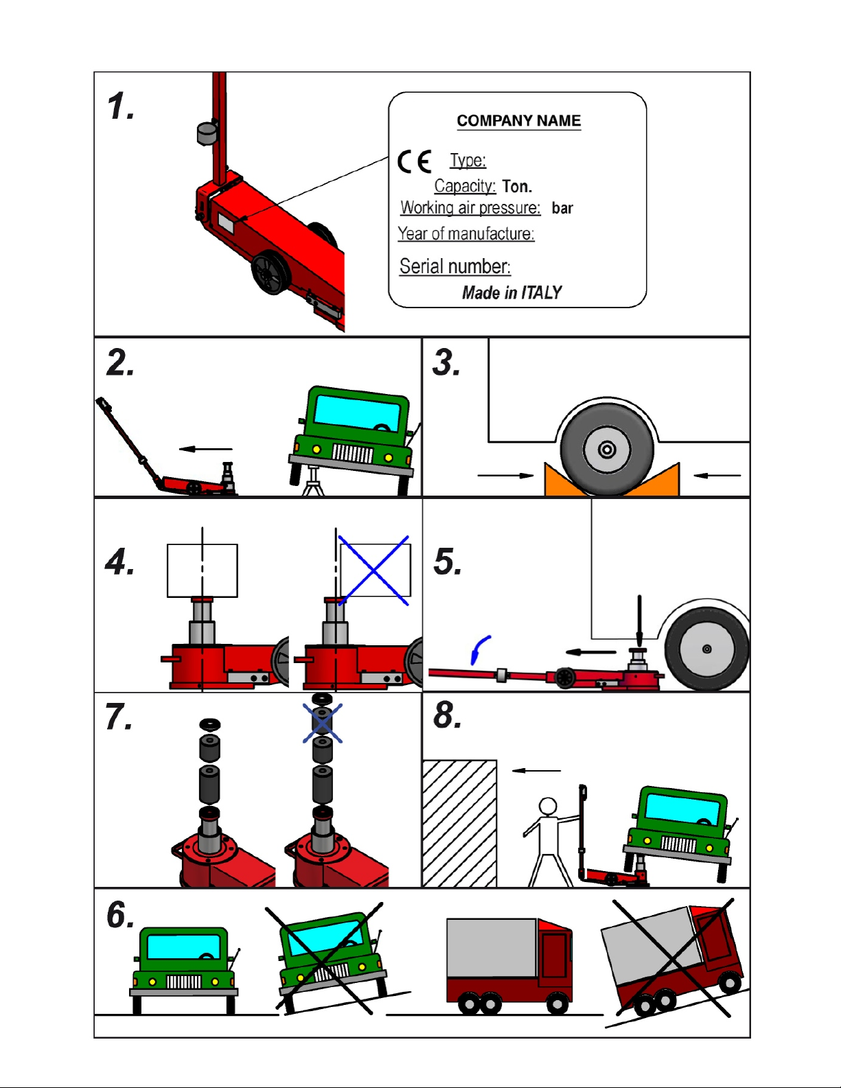
2. Check that the jack has been used observing the conditions listed previously, i.e. horizontally and not slanted. If the
jack has been turned upside down or tipped over, it will stop leaking very soon.
7

THE PISTONS ARE VERY SLOW TO MOVE UP
- Check that the tap, POS. 9 GRP1SOLPOS. 9 GRP1SOL, located between the tank and motor pump is open.
- If the jack malfunctions when moving up, check the spring POS. 17 GRP1GMPPOS. 17 GRP1GMP.
8

Measurements and dimensions - YAK 221/N
A525 mm
20.7 in
B270 mm
10.6 in
C217 mm
8.5 in
D124 mm
4.9 in
E126 mm
5 in
F250 mm
9.8 in
G300 mm
11.8 in
H206 mm
8.1 in
I1400 mm
55.1 in
L1320 mm
52 in
TECHNICAL DATA SHEET
Working air pressure 8 > 10 bar
116 > 145 psi Weight 46 Kg
101 lb
Working temperature -20°C > +50°C
-4°F > 122°F Max. stroke 250 mm
9.8 in
Air consumption 400 nl/min 1st stage capacity 40 t
44 ton (short)
Compatible oils ATF Dexron IID 2nd stage capacity 20 t
22 ton (short)
Pneumatic system pipes Rilsan ø 6x4 mm 3rd stage capacity -
4th stage capacity -
5th stage capacity -
Aerial Noise
Acoustic radiation pressure measured: 60 dBA
Tests carried out in conformity with the standards ISO/R 1680 - 1970. Instrument: LARSON DAVIS 800 B PRECISION ANALYSER
PHONOMETER in conformity with the standards IEC 804 E 651 class 1 set with a Larson Davis Ca 250 114/b 250 Hz calibrator
before and at the end of the measurements.
9

MULTI-LANGUAGE
DISEGNIZEICHNUNGENDRAWINGSDESSINSDIBUJOS
10

11

REQUESTING SPARE PARTS
WHEN ORDERING SPARE PARTS, THE FOLLOWING MUST BE SPECIFIED:
1) LIFT MODEL
2) SERIAL NUMBER
3) PART CODE (CODE)
4) DESIRED QUANTITY
12
KCYAK221/N
Cylinder seals kit
KMYAK221/N
Motor pump seals kit
KBYAK221/N
Block seals kit
SEALS KIT
KXYAK221/N
(KCYAK221/N + KMYAK221/N + KBYAK221/N)
Complete Seals kit

CONTACT INFO:
15270 Flight Path Drive
Brooksville, FL 34604
PH. 352.754.1117
Toll Free. 1.800.352.9852 (US, Canada Only)
Fax: 352.754.4508
ESCO - The Proper Tools to Keep Your Equipment Moving!
Stay Connected with ESCO...
The Proper Tools To
Keep Your Equipment
Scan this Code to Go to
the ESCO website
WWW.ESCO.NET
This manual suits for next models
1
Table of contents
Other Esco Jack manuals

Esco
Esco YELLOW JACKIT 10812 Technical manual

Esco
Esco CYCLONE X Series User manual

Esco
Esco 10807 User manual

Esco
Esco 10493 User manual

Esco
Esco 530AD User manual

Esco
Esco Pro Series User manual

Esco
Esco 90520 User manual

Esco
Esco YAK 22/11 User manual

Esco
Esco 70131 Parts list manual

Esco
Esco 10435 Parts list manual
Popular Jack manuals by other brands

Clarke
Clarke Strong-Arm CTJ2250LP Operation & maintenance instructions

Westward
Westward 15F197 Operating instructions manual

EQUIPRITE
EQUIPRITE 5100790 Operating instructions & parts manual

BorMann
BorMann BWR5050 owner's manual

Draper
Draper TJ2/QL Instruction leaflet

FulTyme RV
FulTyme RV 2105 Installation & operation manual